Abstract— The paper discusses an implemented methodology for Fault Classifier and Fault Locator for locating faults occurring on a double circuit dual feed EHV transmission line, using Artificial Neural Network. The method uses the fundamental frequency components of voltage and current at pre-fault and post-fault condition, measured in each phase at a reference end on one of the lines of the system. The proposed neural fault classifier and fault locator were trained using various sets of data available from a selected power system model by simulating different fault scenarios like - fault types, fault locations, fault resistances and fault inception angles. The proposed scheme for Fault Classifier and Fault Locator gives great promising results which satisfy for a fast and accurate classification and location.
Keywords: Transmission line, fault classifier, fault locator, artificial neural networks
I. INTRODUCTION
A transmission line is one of the most important components of power system which connects the generating station with distribution system. The probability of fault occurring on a transmission line is quite large as it is exposed to open environmental conditions. The various types of faults occurring on a transmission line are: single line to ground faults, double line faults, double line to ground faults, triple line faults and triple line to ground faults.
So it becomes a prerequisite for faster detection and clearance of faults and henceforth ensuring security and stability of system as a whole. The purpose of a protective relays is to clear the fault as quickly as possible, minimize the damage caused due to fault and restore the line quickly. As a result of this it becomes essential to know about the nature of fault occurred in the line and its exact location.
There are 2 main parts to address as regards to the given problem, firstly detection of the fault along with its classification and secondly detecting the location of the fault. For detecting fault and classifying the faults, different fault patterns are required. Many approaches have been shown by researchers for locating the fault on long transmission line. Out of the many methods suggested, fault location methodology involves mainly the following methods:
Methods based on the traveling wave theory: these methods send an electrical pulse along the line and record the signals reflected at both ends. The return time of the pulse from the fault point indicates the distance to that point.
Pranav.D.Raval is working as Asst. Professor in Department of Electrical Engineering,. ADIT Engg. College, New Vallabh VidyaNagar, India. (email: [email protected])
Methods based on assessing electrical magnitudes at fundamental frequencies: these methods record the voltage and/or current signals at the ends of the line under consideration and find its periodic fundamental component both before and immediately after the fault. When processed suitably these fundamental components enable the fault to be located.[1]
II. ANN STURUCTURES
Artificial Neural networks (ANN) are simplified models of biological neuron system. It consists of a massively parallel distributed processing system made of highly interconnected neural computing elements called as “Neurons”, which has the ability to learn and thereby acquire knowledge. The architecture is inspired from structure of cerebral cortex of brain (Tsoukalas and Uhrig, 1997). The pioneering work of McCulloh and Pitts (1943) was foundation of NN architectures. Followed by this was Hebb (1949) who presented a mechanism for learning in biological neurons. ANN comprises of number of neurons which forms the basic processing unit. Each neuron is further connected to other neurons by links. Every neuron receives number of inputs which are modified by ‘weights’. The synaptic weights would either strengthen or weaken the signal which is processed further. To generate the final output the sum of the weighted output is passed on to a non-linear filter called as
‘activation functio’n or ‘Transfer function’ or ‘Squash
function’ , plus a threshold value called ‘bias’ which releases the output. Figure 1 shows the model of ANN.
Fig 1: ANN model
The function of neural network is determined by structure of neurons, connection strengths, and the type of processing performed at elements or nodes. In classification tasks, the output being predicted is a categorical variable, while in regression problems the output is a quantitative variable. Neural network uses individual examples, like set of inputs or input-output pairs, and appropriate training mechanism to
ANN based Classification and Location of Faults
in EHV Transmission Line
Pranav.D.Raval
Inputs Weights
Output
Bias
1
3p
2
p
1
p
f
a
3
w
2
w
1
w
(
+ + +)
=(
∑
+)
= f pw p w p w b f pw b
a 1 1 2 2 3 3 i i
Proceedings of the International MultiConference of Engineers and Computer Scientists 2008 Vol I IMECS 2008, 19-21 March, 2008, Hong Kong
periodically adjust the number of neurons and weights of neuron interconnections to perform desired function. The learning methods for NN can be classified as:
Supervised learning, wherein the input and output patterns are provided. A teacher is assumed to be present during learning process, when a comparison is made between network’s output and correct expected output, so as to determine the error. Unsupervised learning, wherein the target output is not presented to the network. The system learns by itself by adapting to the structural features in input patterns.
Reinforced learning, a teacher though available does not present the expected answer but only indicates if the computed output is correct or incorrect. The information helps in learning process.
III. POWER SYSTEM MODEL
The power system under consideration consists of two 735 KV parallel lines having 200 kms length. The two lines are feed from two ends by generators at 13.8 KV as is represented in the block diagram. The line models are distributed parameter lines. The lines are assumed to be transposed and their parameters R,L,C /km are specified in positive- and zero-sequence components. Each line is shunt compensated by two shunt reactors of 200 MVARs each, connected at line ends which is not indicated in the block diagram. Figure 2 shows the system model used.
Fig 2 : System Model
IV. FAULT CLASSIFIER AND FAULT LOCATOR
The functional block diagram of the fault classifier and fault locator is shown in figure 3, which is part of the proposed relaying scheme. The CT and PT juice is feed to the relay as shown in figure 3 which is placed at one end of the transmission line. The pre fault and post fault voltage and current data is pre processed and then given to the relay.
Fig 3: Relay Model
V. ANN ARCHITECHTURE FOR THE RELAY
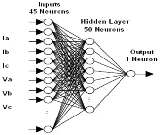
The selection of the network structure depends upon the classification problem involving fault patterns, which ultimately relates to the number of input and output neurons selection. In the paper a Multi layer feed forward neural network is selected. Lesser the number of inputs and outputs less is the space required but imposes the problem of insufficient characterization of the patterns to be classified. So after analyzing number of fault states like: fault types, fault location, fault inception angle, fault resistance, etc number of inputs taken were 45 with 50 hidden layer neurons and 1 output for Fault Classifier. In Fault Locator, the numbers of inputs taken were 6 with 6 hidden layer neurons and 1 output for each type of fault individually was tested and for overall performance checking with all fault types considered a structure with 30 inputs, 30 hidden layer and 1 output was taken for consideration. The transfer functions taken for both are tansig for the hidden layer and linear for the output layer.
Fig 4: ANN Fault Classifier Structure
Power System Model
Pre-fault and
Post-fault data Fault Classifier
Fault Locator Relay
V,I
Proceedings of the International MultiConference of Engineers and Computer Scientists 2008 Vol I IMECS 2008, 19-21 March, 2008, Hong Kong
Fig 5: ANN Fault Locator Structure
Figure 4 and 5 shows the structures used for Fault Classifier and Fault Locator, which are essential modules of Relay.
VI. TRAINING METHOD
Several different training algorithms for ANN are available. All these algorithms use the gradient of the performance function to determine how to adjust the weights to minimize performance. The gradient is determined using a technique called backpropagation, which involves performing computations backward through the network. Taking speed and memory allocation in to account many algorithms are available for implementing the backpropagation method. Levenberg-Marquardt optimization technique is used in the implemented ANN structure.
Simulations were carried out for different fault scenarios for getting various fault patterns. The system model as well as ANN training was done using MATLAB 7.0. The simulations done were for different fault types like LG, LL, LLL,LLLG faults . The fault resistances taken in to consideration were 1Ω and 20Ω for faults occurring at various locations. The instantaneous phasor magnitudes of voltage and current are extracted from each phase by CTs and PTs placed in the system. A sampling rate of 3 KHz, which corresponds to 50 samples per cycle for a 60 Hz cycle, was selected. Preprocessing is a useful method which can significantly
reduce the size of the neural networks based classifiers and improve the performance and speed of training process.[5] The voltage and current signals were processed using an anti-aliasing filter for removing the unwanted frequencies from the sampled signal. A sliding data window is applied to the voltage and current signal as shown in figure 6.
Va,Vb,Vc
Ia, Ib, Ic
Fig 6 : Moving data window applied to the Voltage and Current signals.
Then the voltage and current signals are normalized between a range of -1 to 1. From the processed signals critical features are extracted which differentiate different fault patterns which is done by signal processing stage.
VII. PERFORMANCE RESULTS
The proposed Relay performances were evaluated by applying the preprocessed data to it.
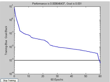
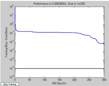
The performance of Fault Classifier and Fault Locator are shown in figure 6 and 7. It can be seen that Fault Classifier is able to perform well in classifying the fault in 60 epochs. At the same time the Fault Locator is able to perform to satisfying level by taking around 300 epochs.
Fig 7: Fault Classifier Performance
Proceedings of the International MultiConference of Engineers and Computer Scientists 2008 Vol I IMECS 2008, 19-21 March, 2008, Hong Kong
Fig 8: Fault Locator performance
The networks’ architectures were decided empirically which involved training and testing both the networks. As shown in Performance graphs, the networks are able to respond to the fault correctly in a timely fashion. The fault is identified just in a few ms which shows that the network is able to detect and classify the fault quite fast. The network outputs remain stable after identifying the fault in case of Fault Locator, which is evident and an indication of the stability of the network over a period of 300 ephocs.
The performance results are shown in table 1 for few fault types classified at individual and overall checking phase of the ANN.
Fault types MSE in Predicting the fault
LG 0.00017765 LL 0.0014277 LLG 0.00097606 LLL 4.3172e-006 All faults 0.00064644
Table 1: Fault Classifier results
The performance of the fault classifier shows that LL fault has least performance compared to others, whereas LLL and LG has got far better performances. Overall Performance for all types of faults results to 0.00064644. In case of LL fault the reduction of the fault impedance results in to difficulty in classifying the fault to greater accuracy.
The Fault Locator testing has been done with three different fault scenarios at 20kms, 100kms and 180kms. The error in fault locating is given by the following formulae. Error (km) = | ANN output − Fault location | Where ANN output is the output of ANN in kms estimating the fault location and Fault location is the actual position in kms. The performance results for the fault locator are enumerated below in the table.
Fault types
(each fault tested for 20, 100 and 180 kms)
MSE in Predicting the Location of faults
LG 0.083333
LL 9.0548e-009 LLG 3.8221e-008 LLL 9.3914e-006 LLLG 4.5976e-010
All faults 0.0063855
Table 2: Fault Locator Results
The performance of fault locator (FL) is having a moderate performance for LG fault where for rest of the faults the FL performance was more far better. The overall performance resulted to 0.0063855.
Performance of the proposed scheme is evaluated using various fault types and encouraging results are obtained. It was shown that the Relay scheme was able to perform fast and correctly for different combinations of fault conditions, e.g. fault type, fault resistance, fault inception angle, fault location.
VIII. CONCLUSION
It has been shown through the implementation done on a Power System model comprising EHV transmission line, an ANN based Fault Classifier and Fault Locator gives satisfactory results. The training of the ANN is done by numerous simulations done on MATLAB 7.0 software package. The various fault scenarios have been taken into consideration which results into variety of patterns presented to the NN. The inputs given to Fault Classifier contain instantaneous voltage and current magnitudes at a reference end, whereas for the Fault Locator unit instantaneous current magnitudes haven been considered. The performance results shows that the ANN based Fault Classifier and Fault Locator provides good results.
REFERENCES
[1] , A. J. Mazon, I. Zamora, J. Gracia, K. Sagastabeitia, P. Eguia, F. Jurado, J. R. Saenz,
Fault Location System on Double Circuit Two-Terminal Transmission Lines Based on ANN’S
[2] Bretas A.S. and Phadke A.G. (2003): Artificial neural networks in power system restoration.—IEEE Trans. Power Delivery, Vol. 18, No. 4, pp. 1181–1186.
[3] Purushothama G.K, Narendranath A.U., Thukaram D. and Parthasarathy K. (2001): ANN applications in fault locators — Electrical Power & Energy System.
[4] T. Dalstein and B. Kulicke, Neural network Approach to Fault Classification for High Speed Protective Relaying,” IEEE Trans. on Power Delivery
[5]. S. Haykin, Neural Networks, IEEE Press, New York, 1994.
[6]. M. Kezunoic, “A Survey of Neural Net Application to
Protective Relaying and Fault Analysis”, Eng. Int. Sys., Vol. 5, No. 4, Dec. 1997, pp. 185-192.
Proceedings of the International MultiConference of Engineers and Computer Scientists 2008 Vol I IMECS 2008, 19-21 March, 2008, Hong Kong