An Efficient Collision Detection Scheme for Generation-2 RFID
Systems
Cheng Jin and Sung Ho Cho
Department of Electronics and Computer Engineering, Hanyang University, Seoul, 133-791, Korea
Abstract
In radio-frequency identification (RFID) systems, tag collision resolution is a significant issue for fast tag identification. Dynamic framed slotted ALOHA (DFSA) is one of the most widely used algorithms to resolve tag collision. Collision detection (CD) plays an important role in determining the efficiency of DFSA-based algorithms because most DFSA-based algorithms determine the next frame size according to the number of collided slots in the current frame. Existing CD methods do not respond quickly enough to detect a collision and have difficulty in distinguishing a collision from noise, resulting in a degradation of system efficiency. This paper presents a CD scheme based on the EPCglobal Class-1 Generation-2 protocol to improve CD efficiency. This scheme enables fast and accurate CD by detecting the number of pulses transmitted by tags. The effectiveness and practical feasibility of the scheme is verified by simulation and implementation. Performance evaluation results show that the proposed scheme achieves faster identification speed than the conventional methods, especially under noise conditions.
Keywords: RFID, access protocols, tag collision, collision detection, ALOHA, Gen2
1. Introduction
Radio-frequency identification (RFID) is an automatic wireless identification technology which has become an attractive solution for supply chain management and industry automation. An RFID system generally consists of an RFID reader and one or more RFID tags, which are typically attached to objects that need to be identified by the reader. To identify tags, the reader sends query commands to the tags, and the tags send response back to the reader.
One primary goal of RFID systems is to identify multiple tags as fast as possible. However, if more than one tag replies to the reader simultaneously, a tag collision occurs and none of the tags can be identified by the reader. Therefore, collision resolution is a critical issue in determining tag identification speed. To resolve the collision problem, many anti-collision algorithms have been presented. There are two main kinds of anti-collision algorithms used in RFID systems: tree-based [1]-[7] and
ALOHA-based [8]-[14]. The tree-based algorithm splits the collided tags into subsets when a collision occurs, then proceeds each subset separately. The process is repeated until all tags are identified. The tree-based algorithm may require much time when the number of tags is large. In ALOHA-based algorithm, the reader divides time into intervals of time slots, and each tag randomly selects one time slot and sends its ID in that time slot. Generally, slots are issued in frames (from which the name framed slotted ALOHA), the size of which is determined by the reader at the beginning of each frame. In a frame, if two or more tags select a same slot to transmit data, a collision occurs and the collided tags retransmit in the next frame. The performance of framed slotted ALOHA (FSA) depends on the number of tags and the frame size. The maximum efficiency of FSA can be achieved when the frame size is equal to the number of tags [15]. Dynamic framed slotted ALOHA (DFSA) is an advanced version of FSA which dynamically changes the frame size according to the number of unidentified tags to optimize the efficiency of FSA. In DFSA, in order to determine the optimal frame size for the next frame, the number of unidentified tags needs to be estimated at the current frame. Therefore, estimating the number of unidentified tags plays a crucial role in determining the efficiency of DFSA.
Recently, many works on tag estimation method have been proposed to improve the performance of DFSA based RFID systems [16]-[19]. In these methods, tag estimation is based on observing the number of empty, successful, and collided slots in a frame. A common feature of these methods is that they operate under assumption that the information of slot occupancy is error free. However, in practical situations, this assumption is not always true due to reasons such as noise. The decision on slot occupancy—whether the slot contains 0, 1, or more replies, directly determines the number of empty, successful and collided slots. Thus, collision detection (CD), detecting a collision and distinguishing it from empty and successful slots, is an important factor in determining the overall system performance.
[20]-[23]. Khasgiwale et al. [20] presented a CD technique that detects the number of tags involved in a collision by analyzing the radar cross-section (RCS) state in the tag signal waveform. This technique enables detection of up to 4 collided tags, however, requires support of professional tools, like the NI-PXI hardware for signal capture and LabVIEW software for signal processing. Liu et al. [21] proposed a CD method by detecting a corruption in the received signal based on the coding characteristics of the signal. Yang et al. [22] proposed a quick CD approach based on checking a newly designed preamble in the tag signal, which is supposed to be implemented on a tag. Kang et al. [23] designed a collision decoding scheme based on a CD performed by detecting the signal length. The drawbacks of these methods are twofold: (1) A relatively long time required wasting slot duration time; (2) When signal corruption is detected, it is difficult to determine whether it is caused by tag collision or just by noise such that the number of unnecessary slots may be increased. These problems can cause the overall identification speed degraded. Thus, to overcome these problems, we propose a CD scheme based on the EPCglobal Class-1 Generation-2 (Gen2) RFID protocol, the anti-collision algorithm of which is a kind of DFSA. In the proposed scheme, CD is achieved by detecting the number of pulses transmitted by tags to detect a collision faster and more accurately.
The remainder of this paper is organized as follows. In Section 2, we describe the operation of the Gen2 RFID system. In Section 3, we describe the proposed CD scheme and analyze its performance. In Section 4, performance evaluation results of the proposed scheme obtained by simulation are presented. In Section 5, we discuss the implementation issues of the proposed scheme. In Section 6, the conclusions are drawn.
2. System Description
Our proposed scheme is for the RFID systems based on the EPCglobal Class-1 Generation-2 RFID air interface protocol, hereafter referred to as the Gen2 protocol. This protocol provides superior new features including flexibility, robustness and fast tag identification. A full specification of the Gen2 protocol can be found in [24]. In the Gen2 protocol, a Q algorithm, which is a variant of the DFSA algorithm, is proposed as the anti-collision algorithm.
In the Q algorithm, a parameter Q which denotes the exponent of frame size ( 2Q) in FSA is used to adjust the frame size. The reader sends a command message which includes the frame size information to tags. In the frame with determined frame size, the tags choose random selected slots to send their IDs to the reader. The operation
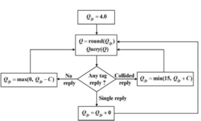
Fig. 1 Q algorithm in Gen2 protocol
of the Q algorithm is illustrated in Fig. 1. In the Q algorithm, the reader receives tag replies slot by slot in a frame. The next frame size is determined by evaluating the slot occupancy of each slot (no reply, single reply, collided reply) in the current frame. In Fig. 1, Qfp is a floating-point representation of Q. The reader rounds Qfp to a nearest integer and substitutes this integer for Q in the next frame. As shown in Fig. 1, Qfp is updated based on three cases of slot occupancy: no reply, single reply, and collided reply. In case of no reply, a constant C is subtracted from Qfp, because it estimates that the current frame size is larger than the number of tags. In case of collided reply, a constant C is added to Qfp, because it estimates that the current frame size is smaller than the number of tags. According to the Gen2 protocol, the initial value of Qfp is 4 and the typical value for C is from 0.1 to 0.5 [24]. The updated Qfp is rounded at the start of each slot to generate a Q. Since C1, there are three possible outcomes after each update of Qfp: Q increments by 1, Q decrements by 1, or Q remains unchanged. If Q changes compared with the current value, the new Q which sets a new frame size to 2Q is sent to the tags in the next frame.
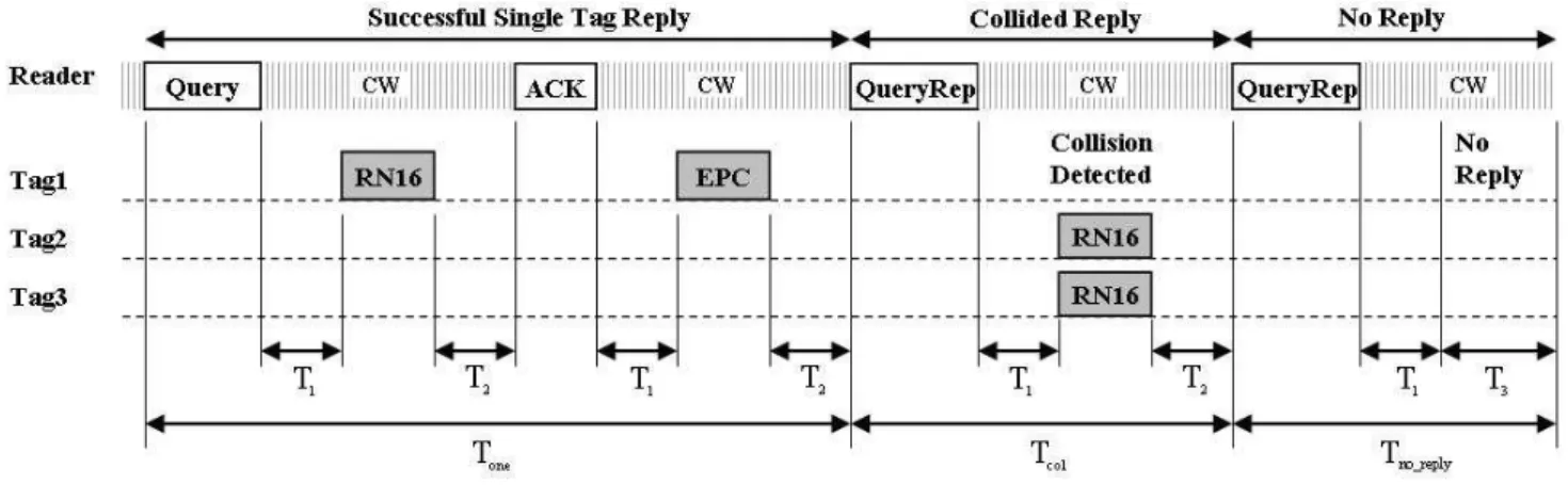
Fig. 2 Tag identification procedure in Gen2 protocol
than 0 waits a QueryRep command from the reader to cause its SN to decrement by 1. QueryRep means “repeat query”; this command is used to cause all tags to decrement their SN by 1. This process continues until the SN becomes 0, after which the procedure for the tag whose SN is zero is followed. Since each tag performs the same procedure independently, there are 3 possible situations after the reader issues a query command (Query, QueryRep, or QueryAdjust) to tags:
(1) Successful Single Tag Reply: Only one tag responds to the reader and the reader successfully receives the RN16. Then the reader acknowledges the tag by sending an ACK. If the tag receives the ACK with a correct RN16, it sends its EPC.
(2) Collided Reply: Multiple tags respond simultaneously and a collision occurs. The reader observes a waveform comprising multiple RN16s. The reader issues a QueryRep or QueryAdjust command to resolve the collision and continue to identify tags. The QueryAdjust command is used to adjust the value of Q and cause all tags to re-select their SN based on the new Q. The value of Q could be incremented by 1, decremented by 1, or remained unchanged according to the Q algorithm.
(3) No Reply: No tag responds to the reader. The reader adjusts the value of Q according to the Q algorithm and continues to identify tags by sending a QueryRep or QueryAdjust command after a waiting time T3. The tags whose SN other than 0 receive the QueryRep command and decrement their SN by 1. This process continues until the SN reaches 0, after which the procedure in (1) will be followed
3. Proposed Collision Detection Scheme
We propose a scheme to improve the CD efficiency. The proposed scheme is based on the idea of carrier sense multiple access with time-split collision detection
(CSMA/TCD) first introduced to enable CD in radio channels [25]. In CSMA/TCD, each terminal transmits a preamble before data transmission, and detects collided transmission from other terminals by carrier sensing. However, in passive RFID systems, since tags are very simple devices without the ability to perform carrier sensing, tags cannot detect or avoid collisions with each other. It is up to the reader to detect and resolve tag collisions. Basing on these considerations, we proposed our CD scheme.
3.1 Description of the Proposed Scheme
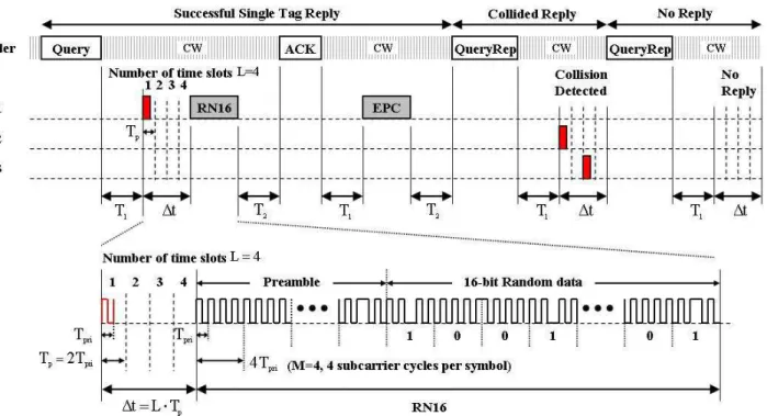
The operation of the proposed CD scheme is illustrated in Fig. 3. In the proposed scheme, each tag transmits a pulse with a length of Tpri in a random selected time slot whose period isTp, among total L time slots before transmitting an RN16. The slot selection is scheduled by controlled randomization process, slotted-ALOHA method. In addition, considering the propagation delay and to guarantee detection of separate individual pulses, each pulse transmission is preceded by an idle period with an equal length to the pulse. In the return link, the reader monitors the pulses transmitted by tags: whether there is zero, one, or more pulses. A collision will be indicated if more than one pulse is detected. Using this method, CD can be performed faster and more accurately in the following two ways: (1) The time required to determine if there is a collision is reduced from a full RN16 transmission time to the pulse detection time t. Since the slot time Tp for one pulse transmission is less than 1-bit period in the RN16, the pulse detection time t is very short compared with the RN16 frame ( t 5% TRN16 for
4
Fig. 3 Tag identification procedure with proposed CD scheme
Aiming at maximizing detect- ability while minimizing implementation complexity, the pulse waveform is proposed to be the same as one subcarrier cycle in the RN16, the period of which is Tpri shown in Fig. 3. For pulse detection, a square-law detector is proposed at the reader receiver for its effectiveness and design simplicity.
3.2 Analysis of the Proposed Scheme
In this section, we analyze and compute the optimal performance that can be achieved using the proposed scheme. The performance metric we consider is the total tag identification time. According to the Gen2 system, the total time to identify n1 tags in error free link can be calculated as
0 no reply_ 1 one 2 col,
tn T n T n T (1) where n0,n1, and n2 are the occurrence times of No
Reply, Single Tag Reply, and Collided Reply shown in Fig. 2, respectively. Accordingly, Tno reply_ ,Tone, and Tcol are the time durations for each case above and can be calculated as
_ 1 3
1 16 2 1 2
1 16 2
,
, .
no reply QueryRep
one Query RN ACK EPC
col QueryRep RN
T T T T
T T T T T T T T T
T T T T T
(2)
Note that Tcol in (2) is the time duration for Collided Reply using the conventional CD method shown in Fig. 2.
For the proposed CD scheme, as can be seen from Fig. 3, the total time to identify the same number of tags can be calculated as
0 _ 3 1
2 _ 3
2
( ) ( )
( )
(1 )( ),
CD no reply one
CD no reply
CD col
t n T T t n T t
n T T t
n T t
(3)
where t L Tp (Fig. 3) is the processing time of CD and CD
is the average success probability of CD which we will analyze in detail in the following.
1
1 1
1 .
k n k
k n p
k L L
(4) Let kn, then we get the probability that all pulses are distributed into the same slot, which is also the pCD_fail we defined above
1 _ (1 ) .
n CD fail k n
p p L (5) Therefore, the success probability of a CD is
1 _ 1 _ 1 (1 ) .
n CD succ CD fail
p p L (6) We use CD in (3) to describe how many times the CD has succeeded in a complete identification process. CD can be calculated as the ratio of successful CD times
_
CD succ
n over all collision occurrence times N
_ . CD succ CD n N
(7)
Among the total N collision occurrences, in each collision, there could be 2, 3, or more tags involved in the collision. Thus, we can define ck as the number of collisions which involve k tags in an inventory frame, the expected value of ck can be calculated as
,
k k
c L p (8) where L is the number of time slots in the frame, and pk
is the probability that k tags are involved in the same slot, which has been defined in (4).Then we have
2 , M k k N c
(9)where M is the maximum number of collided tags which are involved in a collision. Therefore, the expected value of nCD succ_ can be calculated as
1
_ _
2 2
( ) (1 (1 ) ).
M M
k
CD succ k CD succ k
k k
n c p k c L
(10)Substituting (9) and (10) into (7), the CD success probability CD becomes
1 2
2
(1 (1 ) ) . M k k k CD M k k c L c
(11)
Let M2
k k k k
Norm c c , then Normk denotes the normalized occurrence rate of the k-tag involved collision. Finally, (11) becomes
1 2
(1 (1 ) ). M k CD k k Norm L
(12) By dynamically adjusting the frame size L according to the Q algorithm to identify a population of tags, Normk can be computed. A calculation result of Normk is shown in Table 1, obtained by identifying 200 tags (X 200) with an initial frame size L16. When the number of tags X becomes large, Normk shows a little differenceTable 1 Calculated Normk for k (identify 200 tags)
k Normk k Normk
2 0.4714 6 0.0514
3 0.2192 7 0.0352
4 0.1222 8 0.0235
5 0.0767
Fig. 4 Normalized collision occurrence rate Normk for k-tag involved
collision (using results in Table 1)
accordingly since the maximum value of k increases. Based on Table 1, a plot of Normk for different k is shown in Fig. 4. It can be seen that the distribution of
k
Norm is close to a Poisson distribution [15] but not exactly same. The reason could be that the frame length can not always be exactly equal to the number of unidentified tags in the Q algorithm.
In addition, using the same derivation for ck in (8), when identifying n1 tags, we can obtain the expected values of No Reply n0, and Collided Reply n2 , which have been defined in (1). Due to limitation of space, the derivation is not shown. They can be approximated by
0 1.60 , 0.93 .1 2 1
n n n n (13) From (13), we could get a system efficiency of
1 ( 0 1 2) 28%
n n n n , which matches the analytical result in [27].
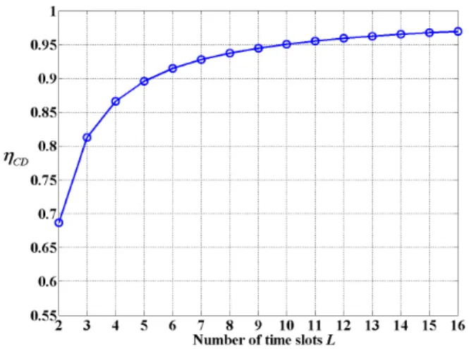
Fig. 5 shows a plot of the analytical calculation of CD for different time slots L. The calculation is based on (12) and Table 1. As shown in Fig. 5, CD increases as the number of time slots L increases. However, the processing time of CD also increases since the processing time is t L Tp, in which Tp is the period of one time slot for pulse transmission (Fig. 3). Therefore, it is necessary to find out the optimal number of time slots—
op
Fig. 5 CD Success probability CD according to number of time slots L
For the proposed CD scheme, the total identification time reduction—tCD, compared with the conventional CD method in (1), can be calculated as
0 1 2 2 _ 3 0 3
1 _ 3 3
=
( ) ( )
[3.53 0.93 ( ) 1.60 ].
CD CD
CD col no reply
p CD col no reply
t t t
n n n t n T T T n T
n L T T T T T
(14) Our goal is to find LLop such that tCD is minimized. Thus, the optimization problem can be stated as
arg max .
op CD
L
L t (15) To solve this, we examine the parameters in (14) in detail. Table 2 gives the typical system parameters of the Gen2 protocol and the values we used in the analysis. We define as the tag to reader (TR) data rate in kbps and as the reader to tag (RT) data rate in kbps. Based on the parameters in Table 2 and (2), the Tp ,
_ 3
col no reply
T T T , and T3 in (14) can be represented as functions ofTRdata rate andRT data rate :
2 Tpri, p
T TcolTno reply_ T3(39M 3) Tpri, and
3 2.8 Tari,
T where Tpri1M and Tari1. Thus, we define
_ 3 3
( ) 2 ,
( ) (39 3) ,
( ) 2.8 .
p
col no reply
A T M
B T T T M M
C T (16)
Then, we can rewrite (14) as
1[3.53 ( ) 0.93 ( ) 1.60 ( )].
CD CD
t n L A B C
(17)
op
L can be found by computing 0. CD
t L
(18) Using CD derived in (12), we have
Table 2 System parameters used in the analysis
Parameters Descriptions Values
Tari Reference time interval for a data-0 inRTlink
25s
RT link data rate 1/Tari=40 kbps
TR link data rate 10~160 kbps
M Number of subcarrier cycles
per symbol in TR link
1, 2, 4, 8
LF TR link frequency M
Tpri Pulse-repetition interval 1/LF
p
T Interval of a time slot for a
pulse in the proposed scheme
2Tpri
1
T Time from reader transmit to
tag response
2.8Tari
2
T Time from tag response to
reader transmit
3Tpri
3
T Time a reader waits after T1, before another command
2.8Tari
Query
T Time of Query command in
RTlink
868.5s
QueryRep
T Time of QueryRep command in
RTlink
207.5s
RN16
T Time of RN16 reply in TR
link
39MTpri
EPC
T Time of EPC reply in TR
link
151MTpri
8 6 5 4
3 2
3.53 ( )
0.4714 0.2192 2 0.1222 3 0.93 ( )
0.0767 4 0.0514 5 0.035 6 0.0235 7 0. A
L L L L
B
L L L
(19) From (19), it can be seen that the solution for L is determined by the TR data rate— and the number of subcarrier cycles per symbol in TR link—M (Fig. 3). With given and M , the optimal number of time slots Lop round L( ) can be found by computing (19). By computing (19) with and M given in Table 2, we found that Lop remains the same for different , but varies according to M. Table 3 shows the optimal number of time slots Lop computed for different values of M .
To verify the results in Table 3, we calculated tCD based on (17) according to different number of time slots
Table 3 Optimal number of time slots Lop according to and M
M L
op L
10~160 kbps
1 2.1225 2
2 2.7413 3
4 3.6346 4
8 4.9119 5
Fig. 6 tCD according to the number of time slots L for different
values of M (Identifying 200 tags, 40kbps, 75 kbps)
4. Performance Evaluation Results
In this section, we present numerical results of the analysis in the last section and compare them with simulation results. We also compare the performance of the proposed method with the conventional methods. The simulation model is based on the Gen2 protocol and the system parameters are specified in Table 2. We set the RT data rate as 40 kbps, the TR data rate as 75 kbps, and the number of subcarriers per symbol M as 4.
Fig. 7 shows the identification time for 200 tags using the proposed CD scheme with various values of time slots L ranging from 2 to 16. The analytical results are based on (3), (12), and (13). As can be seen from Fig. 7: (1) the analytical and simulation results are close to each other; (2) the identification time reaches the minimum at L4 such that verifies the analytical result in the previous section. The same results are observed for different number of tags but not listed here due to limitation of space.
Fig. 8 shows the performance comparison between the proposed CD method and the conventional methods in terms of identification time for different number of tags. As can be seen, an improvement of identification speed is
Fig. 7 Tag identification time for different number of time slots L by using the proposed CD method to identify 200 tags
Fig. 8 Tag identification time comparison (in noise free condition,
4 op
LL in the proposed CD method)
achieved by using the proposed method. As shown in Fig. 8, when identifying 300 tags, the conventional CD method in [21] costs 1.45 sec, [22] costs 1.39 sec, [23] costs 1.50 sec, while the proposed method costs 1.28 sec.
Fig. 9 shows the performance evaluation result in AWGN conditions. We compare the total number of slots (n0 n1 n2) used to identify the same number of tags. An average SNR ranging from 10 to 14 dB is selected to identify 200 tags. As can be seen from Fig. 9, when the channel suffers an increasing level of noise, the conventional CD methods require increasing more slots than the proposed method since the conventional methods have difficulty in distinguishing a collision from single reply corrupted by noise. An incorrect decision on slot occupancy could cause an increment of unnecessary slots.
5. FPGA Prototype Implementation
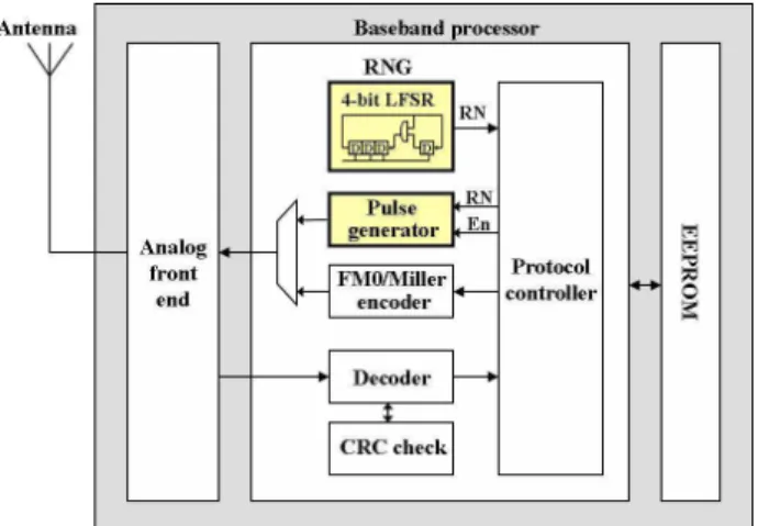
For implementing the proposed scheme, a pulse generation function is required to implement in the tag. Fig. 10 shows the block diagram of the proposed tag chip with emphasis on baseband processor. As shown in Fig. 10, the chip consists of three main sections: analog front end, baseband processor, and electronically erasable programmable read-only memory (EEPROM). The analog front end converts RF power received by the antenna into DC voltage which provides power supply for the rest circuits in the tag. In addition, the analog front end is responsible for receiving signals from the reader, demodulating and digitalizing the data to be used by the baseband processor. It also modulates the tag replies and transmits them to the reader [28]. The baseband processor is responsible for decoding and interpreting the incoming commands from the reader, managing the communication procedure, and generating replies for the received commands. The replies generated by the baseband processor are delivered to the analog front end for sending to the reader. The proposed scheme requires no additional hardware support and can be implemented by using digital logic in the baseband processor.
The baseband processor consists of several modules. The decoder module decodes the incoming data from the analog front end and extracts information included in the received data. The cyclic redundancy check (CRC) check module checks the CRC code in the decoded data for error checking. The encoder module encodes the tag reply data in either FM0 or Miller format and delivers it to the analog front end. The protocol controller is responsible for managing the whole system, deciding what operations should be done, when and what replies should be sent according to the Gen2 protocol.
Fig. 10 Block diagram of the proposed RFID tag chip with emphasis on the baseband processor
The proposed pulse generation function can be implemented by adding a random number generator (RNG) and a pulse generator to the original baseband processor, as shown in Fig. 10. The RNG is used for generating a 4-bit random number (RN) that decides the time slot in which the pulse will be generated. Though the protocol controller includes a unit for generating random numbers for collision arbitration according to the Gen2 protocol, this unit is generally used for generating a 16-bit RN. Based on the analytical results in previous sections, a maximum number of 16 time slots for pulse generation is enough for achieving optimal performance for the proposed CD scheme; therefore, an independent 4-bit RNG is proposed.
Fig. 11 Measured signal waveforms from the prototyped tag FPGA platform
Fig. 12 Experimental setup for functional verification
Based on the proposed architecture, the baseband processor of the tag was implemented in a Xilinx Virtex-5 XC5VSX50T FPGA on a Xilinx ML506 evaluation platform for functional verification. An RFID reader platform based on a Xilinx Virtex-5 XC5VLX330 FPGA, prototyped by Samsung Techwin Co., Ltd., and RFID Research Center in Hanyang University, was used to test the functionalities of the implemented tag. Fig. 12 shows the experimental setup for functional verification of the tag FPGA prototype. Aiming to test the baseband processor of the tag; the reader and tag platforms were
connected by wire to enable communications using baseband signals. As shown in Fig. 12, the reader sends command signals to the tag to trigger the tag operation. Then the reader receives tag reply signals and decodes them. Measurements were done by a logic analyzer (Agilent 16903A) and the measurement results are shown in Fig. 11.
In Fig. 11, waveform 1 and 2 are the reader command signal and the tag reply signal, respectively. A Query command is sent by the reader to the tag at a data rate of 40 kbps. Then an RN16 signal, which contains a pulse in the beginning part of the signal, is sent back by the tag to the reader at a data rate of 75 kbps in Miller-4 encoding format. The received RN16 signal is filtered by a digital bandpass filter in the reader for noise cancellation (waveform 3), and then decoded by the reader. Then the reader sends an ACK command to the tag requiring its EPC. After confirming the RN16 data included in the ACK command, the tag sends an EPC signal to the reader. Waveform 4 and 5 correspond to the decoded data and data synchronization signal of the tag reply signal, respectively. Waveform 6 is a detailed view of the filtered RN16 signal shown in waveform 3. It can be seen that the proposed pulse is successfully generated ahead of the original RN16 signal. The waveform of the pulse is the same as one subcarrier in the RN16 signal. Waveform 7, 8, and 9 show the pulse detection process by using a square-law detector implemented in the reader. The samples of the pulse are saved in a register (waveform 7) and then integrated. The integration result (waveform 9) is compared with a threshold to make a decision (waveform 8). Measurement results show that the tag reply signal is correct and can be successfully decoded by the reader.
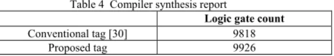
Synopsys Design Compiler based on the TSMC 0.18m technology. The implementation result is compared with that of a conventional Gen2 tag chip fabricated by Samsung Techwin Co., Ltd and RFID Research Center in Hanyang University using the same 0.18m technology [30]. From Table 4, it can be seen that the additional number of logic gates required for implementing the proposed chip is only 1% of the conventional chip. This slight additional cost of logic gates shows that the proposed tag baseband architecture does not increase much complexity of the tag chip and is feasible for practical implementation.
Table 4 Compiler synthesis report
Logic gate count
Conventional tag [30] 9818
Proposed tag 9926
6. Conclusion
In this paper, we proposed a scheme to improve the CD efficiency of the Gen2 RFID systems. An improvement in tag identification speed compared with the conventional methods was verified by simulation. We also discussed development issues for a Gen2 RFID tag to support the implementation of the proposed scheme. Functional measurement and synthesis result of the implemented baseband processor validates the practical feasibility to fabricate the tag chip. Moreover, using the proposed scheme, we are able to detect the number of collided tags in a collision such that will help in estimating the unidentified tag population. Combining the proposed scheme with tag estimation method to maximize system efficiency is our future research subject..
Acknowledgments
This work was supported by Korea Evaluation Institute of Industrial Technology (KEIT), under the R&D support program of Ministry of Knowledge Economy, Korea.
References
[1] J. I. Capetanakis, “Tree algorithms for packet broadcast channels,” IEEE Trans. Inform. Theory, vol. 25, pp. 505-515, Sept. 1979.
[2] D. R. Hush and C. Wood, “Analysis of tree algorithms for RFID arbitration,” IEEE International Symposium on Information Theory, Cambridge, MA, USA, 1998, pp. 107. [3] J. Myung and W. Lee, “Adaptive binary splitting: a RFID tag
collision arbitration protocol for tag identification,” Mobile Networks & Applications, vol. 11, no. 5, pp. 711-722, 2006. [4] J. H. Choi, D. Lee, and H. Lee, “Bi-slotted tree based anti-collision protocols for fast tag identification in RFID
systems,” IEEE Commun. Lett., vol. 10, no. 12, pp. 861-863, 2006.
[5] J. Ryu, H. Lee, Y. Seok, T. Kwon, and Y. Choi, “A hybrid query tree protocol for tag collision arbitration in RFID systems,” in Proc. IEEE International Conference on Communications (ICC’07), Seoul, Korea, 2007, pp. 5981-5986.
[6] Y. Cui and Y. Zhao, “Performance evaluation of a multi-branch tree algorithm in RFID,” IEEE Trans. Commun., vol. 58, no. 5, pp. 1356-1364, 2010.
[7] C. N. Yang, Y. C. Kun, C. Y. Chiu, and Y. Y. Chu, “A new adaptive query tree on resolving RFID tag collision,” 2010 IEEE International Conference on RFID-Technology and Applications (RFID-TA), Guangzhou, China, 2010, pp. 153-158.
[8] H. Vogt, “Efficient object identification with passive RFID tags,” First International Conference on Pervasive Computing, 2002, pp. 98-113.
[9] S. R. Lee, S. D. Joo, and C. W. Lee, “An enhanced dynamic framed slotted ALOHA algorithm for RFID tag identification,” in Proc. The Second Annual International Conference on Mobile and Ubiquitous Systems: Networking and Services (MobiQuitous’05), San Diego, CA, 2005, pp. 166-172.
[10]C. Floerkemeier, “Bayesian transmission strategy for framed ALOHA based RFID protocols,” IEEE International Conference on RFID, Grapevine, TX, 2007, pp. 228-235. [11]C. Lee and H. Cho, “An adaptive RFID anti-collision
algorithm based on dynamic framed ALOHA,” IEICE Trans. Commun., vol. E91-B, no. 2, pp. 641-645, 2008.
[12]Y. J. Lee, D. K. Kwon, and H. N. Kim, “Collision arbitration based on different slot times for slotted-Aloha RFID systems,” IEICE Trans. Commun., vol. E91-B, no. 5, pp. 1416-1422, 2008.
[13]L. Zhu and T. S. P. Yum, “Optimal framed Aloha based anti-collision algorithms for RFID systems,” IEEE Trans. Commun., vol. 58, no. 12, pp. 3583-3592, 2010.
[14]H. Wu and Y. Zeng, “Efficient framed slotted Aloha protocol for RFID tag anticollision,” IEEE Trans. Autom. Sci. Eng., vol. 8, no. 3, pp. 581-588, 2011.
[15]F. C. Schoute, “Dynamic frame length ALOHA,” IEEE Trans. Commun., vol. 31, no. 4, pp. 565-568, 1983.
[16]S. S. Choi and S. Kim, “A dynamic framed slotted ALOHA algorithm using collision factor for RFID identification,” IEICE Trans. Commun., vol. E92, no. 3, pp. 1023-1026, 2009.
[17]J. R. Cha and J. H. Kim, “Dynamic framed slotted ALOHA algorithms using fast tag estimation method for RFID system,” IEEE Consumer Communications and Networking Conference, Las Vegas, USA, 2006, pp. 768-772.
[18]W. T. Chen, “An accurate tag estimate method for improving the performance of an RFID anticollision algorithm based on dynamic frame length ALOHA,” IEEE Trans. Autom. Sci. Eng., vol. 6, no. 1, pp. 9-15, 2009.
[19]J. B. Eom and T. J. Lee, “Accurate tag estimation for dynamic framed-slotted ALOHA in RFID systems,” IEEE Commun. Lett., vol. 14, no. 1, pp. 60-62, 2010.
International Conference on RFID, Orlando, FL, 2009, pp. 131-138.
[21]D. Liu, Z. Wang, J. Tan, H. Min, and J. Wang, “ALOHA algorithm considering the slot duration difference in RFID system,” IEEE International Conference on RFID, Orlando, FL, 2009, pp. 56-63.
[22]L. Yang, J. Han, Y. Qi, C. Wang, Y. Liu, Y. Cheng, and X. Zhong, “Revisting tag collision problem in RFID systems,” 2010 39th International Conference on Parallel Processing, San Diego, USA, 2010, pp. 178-187.
[23]L. Kang, K. Wu, J. Zhang, H. Tan, and L. Ni, “DDC: a novel scheme to directly decode the collisions in UHF RFID systems,” IEEE Trans. Parallel Distrib. Syst., accepted for future publication, vol. 23, pp. 1-8, 2012.
[24]EPCglobal, “EPC radio-frequency identity protocols class-1 generation-2 UHF RFID protocol for communications at 860-960 MHz version 1.2.0,” 2008.
[25]W. F. Lo and H. T. Mouftah, “Collision detection and multitone tree search for multiple-access protocols on radio channels,” IEEE J. Sel. Areas Commun., vol. 5, no. 6, pp. 1035-1040, 1987.
[26]Y. Maguire and R. Pappu, “An optimal Q-algorithm for the ISO 18000-6C RFID protocol,” IEEE Trans. Autom. Sci. Eng., vol. 6, no. 1, pp. 16-24, 2009.
[27]B. Li, Y. Yang, and J. Wang, “Anti-collision issue analysis in Gen2 protocol,” Auto-ID Labs White Paper, WP-HARDWARE-047, 2009.
[28]V. Najafi, S. Mohammadi, V. Roostaie, and A. Fotowat-Ahmady, “A dual mode UHF EPC Gen2 RFID tag in 0.18m CMOS,” Microelectronics Journal, vol. 41, pp. 458-464, Aug. 2010.
[29]J. Melia-Segui, J. Garcia-Alfaro, and J. Herrera-Joancomarti, “Analysis and improvement of a pseudorandom number generator for EPC Gen2 tags,” 14th International Conference on Financial Cryptography and Data Security, Spain, Jan. 2010, pp. 34-46.
[30]K. Y. Jeon and S. H. Cho, “A RFID EPC C1 Gen2 system with channel coding capability in AWGN noise environments,” IEICE Trans. Commun., vol. E92-B, no. 2, pp. 608-611, Feb. 2009.
Cheng Jin received the B.S. degree in automation engineering from Harbin Engineering University, China, in 2005, the M.S. degree in electronics and computer engineering from Hanyang University, Korea, in 2008. Currently, he is working toward the Ph.D. degree at the Department of Electronics and Computer Engineering, Hanyang University, Korea. His research interests include design and implementation of RFID reader systems, optimization of anti-collision protocols, and development of wireless communication systems.
Sung Ho Cho received the B.S. degree in electronics engineering from Hanyang University, Korea, in 1982, the M.S. degree in electrical and computer engineering from University of Iowa, Iowa, in 1984, and the Ph.D. degree in electrical and computer engineering from University of Utah, Utah, in 1989. From 1989 to 1992, he was with the Electronics and Telecommunications Research Institute (ETRI), Korea, as a senior researcher. He is currently with the Department of Electronics and Computer Engineering, Hanyang University, Korea, where he has been a professor since 1992. He has been the director of the Information