Effect of Electric Discharge Machining on Material Removal
Rate and White Layer Composition
SHAHID MEHMOOD*, RIFFAT ASIM PASHA*, AND AMIR SULTAN** RECEIVED ON 03.08.2015 ACCEPTED ON 14.12.2015
ABSTRACT
In this study the MRR (Material Removal Rate) of the aerospace grade (2024 T6) aluminum alloy 2024 T6 has been determined with copper electrode and kerosene oil is used as dielectric liquid. Discharge energy is controlled by electric current while keeping Pulse-ON time and Pulse-OFF time as constant. The characteristics of the EDMed (Electric Discharge Machined) surface are discussed. The sub-surface defect due to arcing has been explained. As the surface material of tool electrode and workpiece melts simultaneously and there are chances of the contamination of both surfaces by the contents of each other. Therefore, the EDS (Energy Dispersive Spectroscopy) of the white layer and base material of the workpiece was performed by SEM (Scanning Electron Microscope) at the discharge currents of 3, 6 and 12 amperes. It was conformed that the contamination of the surface of the workpiece material occurred by carbon, copper and oxygen contents. The quantitative analysis of these contents with respect to the discharge current has been presented in this paper.
Key Words: Electric Discharge Machining, Material Removal Rate, Energy Dispersive Spectroscopy.
* Department of Mechanical Engineering, University of Engineering & Technology Taxila. ** Department of Mechatronics Engineering, University of Engineering & Technology Taxila.
finish, machining time and electrode wear rate [6]. Machining in hydrocarbon oil gives better surface finish and MRR as compared to water based dielectric liquids while using low discharge energies [7].
EDM is a complex machining process, in which the electrical, thermal and chemical processes co-exist [8]. Thermal energy is produced by discrete electric sparks, due to which material of both workpiece and tool electrode melts and even evaporates [9]. At the end of each discharge, the molten material is splashed away by the pressurized dielectric liquid. Hemispherical surface cavities
1.
INTRODUCTION
are formed on the surface which are termed as ‘Crater’ [10]. The surface layer is termed as ‘White layer’, which have different microstructure and metallurgical conditions than the parent material [11-13]. Only 15% of the total quantity of the molten material is removed and the residue resolidifies on the surface [14]. Such layer was also observed in other traditional machining processes [15] but there its thickness is comparatively lower than the EDM machining [15]. Residual stresses are developed due to rapid cooling of the molten material [16]. These stresses are of tensile nature that is detrimental for cyclic loadings [17]. The residual stresses are lower at the surface which are increasing in the depth to maximum in the white layer. The generation of residual stresses depend on the cooling rate of the molten material, which is more at the surface and go on decreasing in the depth. Then the maximum stresses should appear at the surface but these stresses are relaxed by the formation of micro-cracks in the surface. When the amount of residual stresses exceed the limit of rupture strength of the material then cracks generate and cause relaxation in the residual [18-19].
The MRR and tool wear rate have been the focus of different studies [5,20-21]. Where it is was common observation that the MRR generally improved at high discharge energy, but all materials had their unique MRR with respect to the selected conditions. But it was also seen that the surface damage rate in terms of surface roughness, cracks, pits and depth of heat affected zone are also increased with the factors that result high MRR [22]. Each material have different optimized setting of parameters for high surface finish and better machining rate. Saleem et. al. [23] investigated that the discharge current has dominating influence on surface finish and MRR as compared to parameters such as Pulse-ON time, Pulse-OFF time, servo speed and machining time etc. A. Torres et. al. [24] have reported for EDM of Inconel 718
that current intensity and Pulse-ON time are the most influential and duty cycle and voltage are least influential parameters on surface finish and MRR. Choudhary et. al. [25] have determined the effect of process parameters on the newly developed Nomonic 75 alloy and found that current, pulse-ON time and polarity are most influential on the surface roughness. Positive polarity tool electrode results maximum contamination of the surface layer by the carbon contents.
The rapid cooling rate in EDM is also associated with the refined grain structure as compared to grinding and turning process [26]. During machining the surfaces of both electrodes melt and due to the sudden change in the pressure of the plasma as well as by dielectric liquid, there are chances of the surface contamination of one material with the contents of other material [12,27]. Therefore, the resulting surface of the workpiece after EDM at different discharge currents is characterized by EDS. In this investigation, the material removal rate of aerospace grade (2024 T6) aluminum alloys has been investigated. A critical defect that occurred while machining for higher MRR has also been elaborated in this study.
2.
EXPERIMENTAL SETUP
Aluminum alloy 2024 T6, in the form of extruded rods with 22mm diameter had been used. Its physical and mechanical properties are presented in Table 1. Small cylindrical specimen of 20x20mm were prepared on lathe machine.
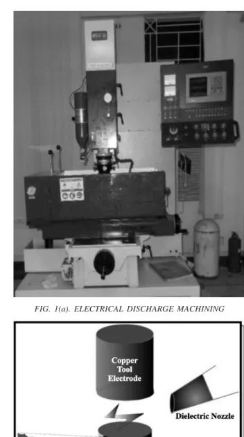
Specimens were clamped on the bed of EDM with a for k-type clamp as shown in Fig. 2. Pure commercial grade copper material was used for tool electrode with have slightly more diameter than the workpiece. The physical properties of copper are represented in Table 2.
Side flushing of the hydro-carbon based kerosene oil was provided with the pressure of 0.9 kg/cm2. The machining
was performed at varying current levels of 3,4.5, 6, 9, and 12 Amperes. The other constant parameters are presented in Table 3. The machined surface of the specimen have contents of kerosene oil, carbon particles and debris. Before determination of MRR, these free particles were removed by acetone liquid in a ultrasonic vibrating chamber for ten minutes.
A digital balance with a resolution of 0.1 mg was used for weighing the specimen before and after machining. Thus the accuracy of the digital balance for weighing of the removed material is ±0.05 mg. Machining time was observed by a digital stopwatch. The MRR in mm3/min
was determined by the relation by:
MRR (mm3/min)= (m
1-m2)/tm . ρ
Where m1 is Mass (gram) of the material before machining, m2 is Mass (gram) of the material after machining, tm is Machining time (minute) and ñ is Density of the material (gram/mm3)
The EDS was performed on the field-emission SEM, MIRA 3 XMU, TESCAN, USA. The prepared sample are mounted on the holders of SEM chamber. Dry nitrogen gas is used to evacuate air completely from the chamber.
Accelerating voltage of 20KV is used for this analysis. In this analysis all elements were analyzed with five iterations and results are shown with all elements.
y ti s n e D ) c c / g
( H(aHrdRnBe)ss
t a e H ci fi c e p S y ti c a p a C ) K . g k /J ( l a m r e h T y ti v it c u d n o C ) K . m / W ( ci rt c el E y ti v it si s e R
(Ω-cm)
f o d o M y ti ci ts al E ) a P G ( /s d i u q i L e r u t a r e p m e T s u d il o S
(oC) 8
7 .
2 78 875 151 4.49E-6 72.4 638/502
TABLE 1. PHYSICAL AND MECHANICAL PROPERTIES OF AL 2024 T6
FIG. 1(a). ELECTRICAL DISCHARGE MACHINING
3.
RESULTS AND DISCUSSION
3.1
Surface and Sub-Surface Observations
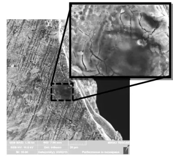
EDM removes the surface material in the form of debris and craters are formed on the surface. The resulting surface is non-reflective and non-directional. The material splattered after each discharge and resolidified on the lips of the crater. The crater and globule sizes are found the characteristics of each discharge current level. The characteristic EDMed surface formed at the discharge current of 9A is shown in Fig. 3.
Arcing is one of the major problem of EDM that can deteriorate the material integrity. Such defects made the EDM process very sensitive that needs much care as compared to traditional machining processes. This defect
is shown in Fig. 4 that occurred while machining at the discharge current of 12A. The dielectric liquid behaves as an insulator material between oppositely charged electrodes. At the start of machining process the gap between electrodes is decreased and monitored by servo control unit. When electrodes come closer the existing electrostatic field among the near ends of electrodes becomes stronger and the atoms of dielectric liquid get polarized. With the increase of voltage and decrease in the gap a limit approaches when the dielectric liquid ionizes and electron and positive ions of the dielectric liquid move towards oppositely charged electrodes. These charged particles collide with the surface of oppositely charged electrodes and heat is produced due to transfer of kinetic energy of these particles to the electrode material. High energy electrons causes more MRR than
t a e H ci fi c e p S
) K . g k /J
( Therm(aWlC/mo·nKdu)citvtiy SpecficiG(gr/acvmti3y)at20°C (×10C-6T(E1°/C)) BoilingT(°eCm)perature Mel(itn°gC)Point
5 8
3 380.7 8.9 17 2595 1083
r e t e m a r a
P ON itme OffTime Votlage Gape Poalrtiy Deielcrtci e
u l a
V 60µs 4µs 110V 5 Poisitve Keroseneoli
TABLE 2. PHYSICAL PROPERTIES OF COPPER ELECTRODE [28]
TABLE 3. CONSTANT PARAMETERS FOR EDM
FIG. 2. EXPERIMENTAL SETUP
SPECIMEN CLAMP DESIGN
the positive ions [30]. Therefore, positive polarity is provided to workpiece for high MRR. This material is removed in the form of debris by the dielectric liquid. But, if the gap between the electrodes is not sufficient, then some debris remained suspended between these electrodes, a bridge is formed and localized electric spark generates high thermal energy. Due to which extensive melting of the material occur that has more depth comparative to actual machined surface. The subsequence rapid cooling of the material generate residual stresses that causes cracking below the normal white layer. Therefore, proper flushing of the debris is suggested for higher MRR so that such defects could be avoided.
3.2
Material Removal Rate
The MRR has been determined for five discharge current levels. The MRR is found less for lower discharge current and more for high discharge current, Fig. 5. As high discharge current produces intense sparks that melts more surface material in the form of large crater size. The results are shown in Table 4 and presented in Fig. 5. These observations are in accordance with the
qualitative analysis of MRR of tungsten carbide, Nickle based alloy and steel based alloy at different current values [24,28,31].
FIG. 3. CHARACTERISTIC ED MACHINED SURFACE
. o
N Dsic(hAarmgpeeCreu)rrent (mMmR3/Rmin)
.
1 3 8.15
.
2 4.5 11.60
.
3 6 28.38
.
4 9 62.66
.
5 12 91.27
FIG. 4. EXTENSIVE MATERIAL MELTING BELOW THE WHITE LAYER
FIG. 5. MRR (MM3/MIN) VS DISCHARGE CURRENT
(AMPERES)
3.3
Energy Dispersive Spectroscopy
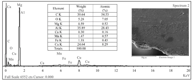
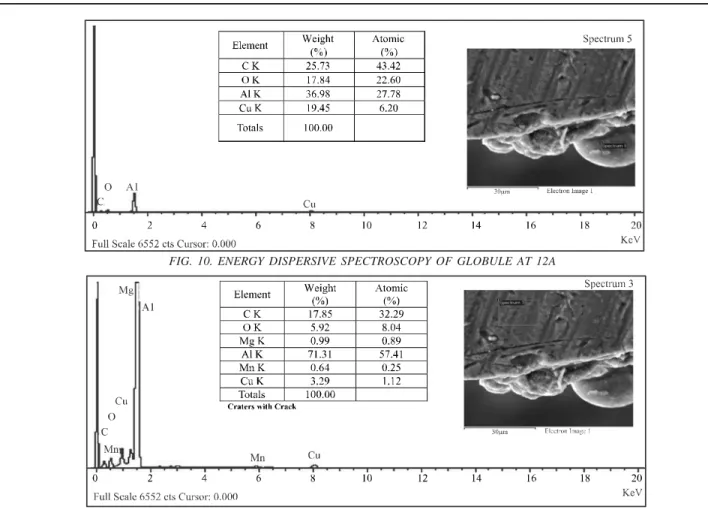
EDS spectroghs are obtained for 3A, 6A, 9A and 12A, which are shown in Figs. 6-9, as well as for globule and base material, shown in Figs. 10-11 respectively. The EDS analysis shows that Al, C and Cu are the major components of the white layer and their quantity is dependent on the discharge current as summarized in Table 5 and Fig. 12. It is found that the white layer is contaminated by Cu at lowest current only, where the inter-electrode gap is smallest due to which material transfer might have occurred. Whereas, Copper is the major alloying element of 2xxx aluminum alloys that has an amount up to 4%. The contamination of the white layer by the carbon contents is observed for all discharge current levels. Where the amount of carbon contents is inversely proportional to the discharge current. These carbon content are transferred from the kerosene oil that disintegrated at the very high discharge temperature upto 40,000 K [32-33]. At low discharge current, the white layer is comparatively thinner than that of high discharge current and at lower discharge current the machining time is large to remove equal quantity of the workpiece material than higher discharge current [28]. Therefore, the concentration of carbon contents is more for lower discharge current than the higher discharge current.
Overall the total quantity of impurities is high at lower discharge current due to which the amount of aluminum element is smaller at the lower discharge current. The contamination of the EDMed surface by the transfer of copper electrode material was also observed by Guo, et. al. [34] for Fe-Mn-Al alloy. The EDS analysis of the globule that was formed at discharge current of 12A has shown that the amount of both copper and carbon is increased. But for the white layer formed at the same discharge current the amount of copper was not increased. Its reason could be attributed as the globules are formed by the vaporized material which might have jumped and went close to the tool electrode during machining and then fell down on the surface of the workpiece. Also the high vaporizing temperature also increases mobility of the globule particles due to which the contamination rate might have raised. Oxygen does not exist during machining in the kerosene oil but when material is exposed to open air, the machined surface is oxidized. The EDS of the base material has been presented for reference purpose and it is clearly observed that the amount of carbon, copper and aluminum elements are nearly equal to that of the white layer formed at the discharge current of 12A. This means that the white layer formed at high discharge current has little or no contamination of the impurities.
Spectrum 2
Fe
Fe Cu Cu
50 m Electron Image 1
Ca
Mn Ca Mg
A1
C O
Cu Mn
0 2 4 6 8 10 12 14 16 18 20
KeV Full Scale 6552 cts Cursor: 0.000
Element Weight (%) Atomic (%)
C K 19.55 36.76
O K 5.62 7.93
Mg K 0.42 0.39
Al K 58.64 49.08
Si K 0.17 0.14
Ca K 0.28 0.16
Mn K 1.66 0.68
Cu K 13.66 4.85
Totals 100.00
FIG. 7. ENERGY DISPERSIVE SPECTROSCOPY OF WHITE LAYER AT 6A
FIG. 8. ENERGY DISPERSIVE SPECTROSCOPY OF WHITE LAYER AT 9A
S D
E Weight(%C)opper Weigh(t%C)arbon Weight(%Al)uminum Weigh(t%O)xygen A
3 24.64 30.64 35.89 5.28
A
6 3.23 26.64 56.32 11.48
A
9 13.66 19.55 58.64 5.62
A 2
1 3.19 16.48 73.35 5.53
el u b o l
G 19.45 25.73 36.98 17.84
l ai r e t a M e s a
B 3.29 17.85 71.31 5.92
TABLE 5. CONTENTS OF MAJOR ELEMENTS IN WHITE LAYER, GLOBULE AND BASE MATERIAL
FIG. 10. ENERGY DISPERSIVE SPECTROSCOPY OF GLOBULE AT 12A
FIG. 11. ENERGY DISPERSIVE SPECTROSCOPY OF BASE-MATERIAL
4.
CONCLUSION
The white layer is extensively contaminated by carbon content for all discharge currents and the amount of carbon contents is inversely proportional to the discharge current. The contamination of the copper contents only observed for 3 ampere discharge current level. The globules have relatively more contamination of the impurities than the white layer. The MRR is quantified for investigated discharge current levels and is found proportional to the discharge current for Al 2024T6, which is in agreement with the results of previous studies performed for other materials. The crater and globule sizes are the characteristic of the discharge current at which EDM is performed. At higher discharge currents the MRR increases, so proper flushing of removed debris from inter-electrode gap have been suggested so that the arcing phenomenon could be avoided. Otherwise severe arcing can cause high localized melting that results in generation of high residual stresses and subsequently severe cracking below the white layer.
ACKNOWLEDGEMENTS
This research work was funded and supported by University of Engineering & Technology, Taxila, Pakistan, under Research Grant No. FME-ME-250, which is highly acknowledged. Special thanks to Technopak Engineering Private Limited, for his technical and logistic support during sample preparation and Institute of Space Technology for scanning electron microscopy.
REFERENCES
[1] Ho, K.H., and Newman, S.T., “State of the Art Electrical Discharge Machining (EDM)”, International Journal of Machine Tools and Manufacture, Volume 43, No. 13, pp. 1287-1300, UK, June, 2003.
[2] Guo, Y.B., Li, W., and Jawahir, I.S., “Surface Integrity Characterization and Prediction in Machining of Hardened and Difficult-to-Machine Alloys: A State-of-Art Research Review and Analysis”, Machining Science and Technology, Volume 13, No. 4, pp. 437-470, USA, December, 2009.
[3] Kunieda, M., Lauwers, B., Rajurkar, K.P., and Schumacher, B.M., “Advancing EDM through Fundamental Insight into the Process”, CIRP Annals -Manufacturing Technology, Volume 54, No. 2, pp. 64-87, Switzerland, 2005.
[4] Dursun, T. and Soutis, C., “Recent Developments in Advanced Aircraft Aluminium Alloys”, Materials & Design, Volume 56, No., pp. 862-871, UK, December, 2014.
[5] Jabbaripour, B., Sadeghi, M.H., Faridvand, S., and Shabgard, M.R., “Investigating the Effects of EDM Parameters on Surface Integrity, MRR and TWR in Machining of Ti–6Al–4V”, Machining Science and Technology, Volume 16, No. 3, pp. 419-444, USA, August, 2012.
[6] Muthuramalingam, T., and Mohan, B., “A Review on Influence of Electrical Process Parameters in EDM Process”, Archives of Civil and Mechanical Engineering, Volume 15, No. 1, pp. 87-94, Poland, January, 2015. [7] Chakraborty, S., Dey, V., and Ghosh, S.K., “A Review on
the Use of Dielectric Fluids and their Effects in Electrical Discharge Machining Characteristics”, Precision Engineering, Volume 40, pp. 1-6, USA, April, 2015. [8] Andrea Gatto, E.B.A.L.I., “Aluminium Alloys, Theory
And Applications”, InTech, Chapter-17, pp. 355-376, UK, February, 2011.
[9] Yadav, V., Jain, V.K., and Dixit, P.M., “Thermal Stresses Due to Electrical Discharge Machining”, International Journal of Machine Tools and Manufacture, Volume 42, No. 8, pp. 877-888, UK, March, 2002.
[10] Bojorquez, B., Marloth, R., and Es-Said, O., “Formation of a Crater in the Workpiece on an Electrical Discharge Machine”, Engineering Failure Analysis, Volume 9, No. 1, pp. 93-97, USA, August, 2002.
[11] Zhang, Y., Liu, Y., Ji, R., and Cai, B., “Study of The Recast Layer of a Surface Machined by Sinking Electrical Discharge Machining Using Water-in-Oil Emulsion as Dielectric”, Applied Surface Science, Volume 257, No. 14, pp. 5989-5997, Netherlands, January, 2011. [12] Cusanelli, G., Hessler-Wyser, A., Bobard, F., Demellayer,
[14] Ramasawmy, H., and Blunt, L., “Effect of EDM Process Parameters on 3D Surface Topography”, Journal of Materials Processing Technology, Volume 148, No. 2, pp. 155-164, Switzerland, 2004.
[15] Guo, Y.B., and Sahni, J., “A Comparative Study Of Hard Turned And Cylindrically Ground White Layers”, International Journal of Machine Tools and Manufacture, Volume 44, No. 2-3, pp. 135-145, UK, 2004. [16] Ekmekci, B., “Residual Stresses and White Layer in
Electric Discharge Machining (EDM)”, Applied Surface Science, Volume 253, No. 23, pp. 9234-9240, Netherlands, June, 2007.
[17] Kruth, J.P., Stevens, L., Froyen, L., and Lauwers, B., “Study of the White Layer of a Surface Machined by Die-Sinking Electro-Discharge Machining”, CIRP Annals - Manufacturing Technology, Volume 44, No. 1, pp. 169-172, Switzerland, 1995.
[18] Subramanian, R., Marimuthu, K., and Sakthivel, M., “Study of Crack Formation and Re-Solidified Layer in EDM Process on T90Mn2W50Cr45 Tool Steel”, Materials and Manufacturing Processes, (To be Accepted), USA, 2012.
[19] Lee, H.T., and Tai, T.Y., “Relationship between EDM Parameters and Surface Crack Formation”, Journal of Materials Processing Technology, Volume 142, No. 3, pp. 676-683, Switzerland, October, 2003.
[20] Daneshmand, S., Kahrizi, E.F., Abedi, E., and Abdolhosseini, M.M., “Influence of Machining Parameters on Electro Discharge Machining of NiTi Shape Memory Alloys”, International Journal of Electrochemical Science, Volume 8, No., pp. 3095-3104, Serbia, March, 2013.
[21] Sivam, S.P., Michaelraj, A.L., S, S.K., R.V., and D.D., “Effects of Electrical Parameters, its Interaction and Tool Geometry in Electric Discharge Machining of Titanium Grade 5 Alloy with Graphite Tool”, Proceedings of the Institution of Mechanical Engineers, Part-B, Journal of Engineering Manufacture, Volume 227, No. 1, pp. 119-131, UK, November, 2012. [22] Tai, T., and Lu, S., “Improving the Fatigue Life of Electro-Discharge-Machined SDK11 Tool Steel via the Suppression of Surface Cracks”, International Journal of Fatigue, Volume 31, No. 3, pp. 433-438, UK, 2009.
[23] Saleem, M.Q., Khan, A.R., and Mufti, N.A.,
“Performance Optimization of Electrical Discharge Machining (Die Sinker) for Al-6061 via Taguchi Approach”, Mehran University Research Journal of Engineering & Technology, Volume 34, No. 2, pp. 183-195, Pakistan, April, 2015.
[24] Torres, A., Puertas, I., and Luis, C.J., “Modelling of Surface Finish, Electrode Wear and Material Removal Rate in Electrical Discharge Machining of Hard-to-Machine Alloys”, Precision Engineering, Volume 40, pp. 33-45, USA, April, 2015.
[25] Choudhary, R., Gupta, V.K., Batra, Y., and Singh, A., “Performance and Surface Integrity of Nimonic75 Alloy Machined by Electrical Discharge Machining”, Proceedings of Materials Today, Volme 2, No. 4-5, pp. 3481-3490, UK, 2015.
[26] Ramesh, A., Melkote, S.N., Allard, L.F., Riester, L., and Watkins, T.R., “Analysis of White Layers Formed in Hard Turning of AISI 52100 Steel”, Materials Science and Engineering: A, Volume 390, No. 1-2, pp. 88-97, Switzerland, 2005.
[27] Shabgard, M., Oliaei, S.N.B., Seyedzavvar, M., and Najadebrahimi, A., “Experimental Investigation and 3D Finite Element Prediction of the White Layer Thickness, Heat Affected Zone, and Surface Roughness in EDM Process”, Journal of Mechanical Science & Technology, Volume 25, No. 12, pp. 3173-3183, South Korea, 2011. [28] Shabgard, M., Seyedzavvar, M., and Oliaei, S.N.B., “Influence of Input Parameters on the Characteristics of the EDM Process”, Strojniški Vestnik – Journal of Mechanical Engineering, Volume 57, No. 9, pp. 689-696, Slovenia, June, 2011.
[29] Arooj, S., Shah, M., Sadiq, S., Jaffery, S.H.I., and Khushnood, S., “Effect of Current in the EDM Machining of Aluminum 6061 T6 and its Effect on the Surface Morphology”, Arabian Journal for Science and Engineering, Volume 39, No. 5, pp. 4187-4199, Saudi Arabia, 2014.
[30] Yoo, B.H., Min, B.-K., and Lee, S.J., “Analysis of the Machining Characteristics of EDM as Functions of the Mobilities of Electrons and Ions”, International Journal of Precision Engineering and Manufacturing, Volume 11, No. 4, pp. 629-632, South Korea, August, 2010.
[31] Lee, S.H., and Li, X.P., “Study of the Effect of Machining Parameters on the Machining Characteristics in Electrical Discharge Machining of Tungsten Carbide”, Journal of Materials Processing Technology, Volume 115, No. 3, pp. 344-358, Switzerland, September, 2001.
[32] DiBitonto, D.D., Eubank, P.T., Patel, M.R., and Barrufet, M.A., “Theoretical Models of the Electrical Discharge Machining Process. I. A Simple Cathode Erosion Model”, Journal of Applied Physics, Volume 66, No. 9, pp. 4095, USA, July, 1989.
![TABLE 2. PHYSICAL PROPERTIES OF COPPER ELECTRODE [28]](https://thumb-eu.123doks.com/thumbv2/123dok_br/18120286.324127/4.918.92.827.537.1052/table-physical-properties-of-copper-electrode.webp)