Vol-7, Special Issue-Number2-April, 2016, pp205-214 http://www.bipublication.com
Research Article
Neuro-fuzzy based Controller for Solving Active Power Filter
Homayoun Ebrahimian1,* and Hamed Arabzadeh2
1
Department of Basic Sciences, School of Medicine, Ardabil University of Medical Sciences, Ardabil, Iran
2
Department of Engineering, Ardabil Branch, Islamic Azad University, Ardabil, Iran
ABSTRACT
In this paper, two soft computing techniques by fuzzy logic, neural network are used to design alternative control schemes for switching the APF active power filter (APF). The control of a shunt active power filter designed for harmonic and reactive current mitigation. Application of the mentioned model has been combined by an intelligent algorithm for improving the efficiency of proposed controller. Effectiveness of the proposed method has been applied over test case and shows the validity of proposed model.
I. INTRODUCTION
SOFT COMPUTING is a technology to extract information from the process signal by using expert knowledge. It either seeks to replace a human to perform a control task or it borrows ideas from how biological systems solve problems and applies it to control processes. The main areas in soft computing notably are fuzzy logic, neural network, rough sets, etc. Soft computing has experienced an explosive growth in the last decade partially due to uncertainties and vagueness in the process signal and occurrence of random events, and partially due to nonlinearity and complexity of the processes. The system can be complex with nonlinearity and parameter variation problems. An intelligent or self-organizing control system can identify the model, if necessary, and give the predicted performance even with a wide range of parameter variation. Soft computing is an alternative solution to meet the process and user’s requirements simultaneously. In this paper we have developed algorithms based on fuzzy logic, neurofuzzy for controlling the switching of a shunt active power filter (APF)
configuration. The comparative merits and demerits of these schemes including those of a conventional PI algorithm are discussed.
II. PROBLEM IDENTIFICATION
the APF .In this paper, we have considered the control strategy based on the regulation of the dc capacitor voltage. Soft computing techniques have been applied to APF control to a certain extent however; detailed investigations and possible combinations of these methods have not been explored. The objective of this paper focuses mainly on developing soft computing algorithm-based control strategies for switching single-phase shunt APFs. They offer an efficient control method under the uncertain and varying load and supply conditions and offer a much better dynamic response.
III. ACTIVE POWER FILTER
The main objective of the APF is to compensate the harmonic currents due to the non linear load. These filters are generally designed around a PWM bridge converter having a capacitor on the dc side. The switching frequency of the bridge determines the frequency range of harmonic currents that are generated by APF. It is expected to correct up to f/5orf/10 . The aim now is to control this switching so that the voltage source lines, the nonlinear load, and the filter work together. This leads to designing the control algorithm which is best suited to compensate the harmonic and reactive currents. In the following sections, we have presented the study using some intelligent algorithms, such as fuzzy logic, neurofuzzy, which take into account the uncertainty due to the dynamics in load.
A. PI Algorithm
The PI control scheme involves regulation of the dc bus to set the amplitude of reference current for harmonic and reactive
power compensation [4], [5]. Assuming no power losses in the compensator, the dc-link voltage remains constant if no real power is drawn from it. However, practically, there are switching losses in the APF that increase with the increase in the reactive power demand of the load. These losses are supplied by the capacitor, and its voltage drops.
The capacitor also has to supply active power during transient states when the real-power demand of the load increases. Thus, in either case, the capacitor voltage drops.
Similarly, the capacitor voltage will increase if the reactive/real power demand of the load decreases. Hence, by monitoring the capacitor voltage, the real power supplied by the APF can be estimated and the amplitude of the fundamental active component of the supply current was estimated indirectly using the real-power balance theory. The control is on the supply current directly. Only one sensor is required to sense the supply current and there is no delay in the compensation process. A PI control algorithm is used to regulate the dc link voltage of the shunt APF. This method is preferred because the reference current is generated without calculating either the load current harmonics or the load reactive power. This results in an instantaneous compensation process and the associated hardware is simple to implement, thereby increasing system reliability. The control variables used by the PI control algorithm are the dc bus voltage, supply current, and supply voltage. In the control scheme investigated here, a sample-and-hold circuit is used to take capacitor voltage samples at every 10 ms for a supply frequency of 50 Hz. The error input to thePI controller and the amplitude of the supply current provided by the controller are thus made available at zero crossing only and the supply current is maintained constant for the entire period of one cycle. Hence, the correction action is achieved every half cycle. The ripple in the capacitor is eliminated with this technique and there is no need to use lowpass filter. The dc capacitor voltage has to be maintained at more than twice the peak supplyvoltage for proper operation of the shunt APF system. This is taken as the reference dc-link voltage (Vref)and compared with the actual voltage of the capacitor (Vdc). The resulting error at the th sample instant is expressed as
The compared result is fed to a PI controller and the output of the PI controller is given by
the the sampling instant. This output of the controller is limited to a safe permissible value depending on the rating of the APF switches, and the resulting limited output is taken as the peak value of the reference supply current for harmonic and reactive power compensation. The phase information is obtained by a unit amplitude sine wave derived from the mains voltage. The reference current so obtained is compared with the actual supply current and fixed frequency PWM is used to generate the switching signals for the APF converter. The switch control applies Vf or -Vf on the ac side, forcing the compensation current to track the reference current. The APF, the following equations can be written:
The filter output voltage can be controlled only by the duty cycle of the bridge. Therefore, we obtain
The problem of a soft computing control algorithm is, therefore, to determine the duty cycle in such a way that remains as constant as possible and produces the right harmonic-compensated current.
B. Simulation Results
The harmonic model of a computer consisting of a diode bridge rectifier with a large smoothing capacitor is used to represent a typical nonlinear (NLL) load. The load was simulated for a supply voltage of 230 V, 50 Hz and and the performance parameters were found as 3.41 A, = 149.7%, = 0.124%, = 0.98, 1.497, and 0.585. It is seen that the root mean square (rms) supply current is increased due to the presence of harmonics and low power factor.
Due to the presence of the smoothing capacitor, the load current is seen to be discontinuous [Fig. 1(c)].
The PI control algorithm is applied to control a shunt APF for compensating harmonic and reactive power drawn by the computer load. The
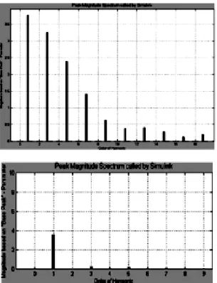
system is simulated using MATLAB and the results are presented in Fig. 1. The waveforms for supply voltage, supply, load, and filter currents and dc-link voltage are shown in Fig. 1(a)–(e). It can be seen from Fig. 1(b) and (c) that the supply current becomes sinusoidal while the load continues to draw current in nonsinusoidal pulses. The harmonic spectrum of the supply current before and after compensation is shown in Fig. 2(a) and (b), respectively. The total harmonic current distortion is reduced from 149.7% of the uncompensated load to 4.49% after compensation. The power factor is improved to 0.98 from 0.585 of the uncompensated load. The compensated rms supply current is 2.668 A and it is seen that the rise in supply current due to the presence of harmonics is effectively brought down. The dynamic response for addition and removal of the load can be observed from Fig. 1(b). The supply current settles smoothly to a new steady-state value within a half cycle of a 50% decrease in load at0.1 ms and a 200% increase in load at 0.3 ms. There is a small change in the dc-bus voltage [Fig. 1(e)] at the instant of disturbance in the load to balance extra energy due to an increased or decreased level of compensation. The dc-bus voltage settles to its steady-state value within a few cycles.
The APF with PI control for a self-supporting dc bus has several advantages viz; instantaneous compensation, no need to sense reactive power demand or load harmonics, the advantage of using only one current sensor, and simple control logic and hardware.
However, in this scheme, the nonlinear model of the APF system is assumed to be linear and the PI controller design is based on a mathematical model of the linearized system.
Fig. 1. Dynamic performance of PIAPF with the computer load.
Fig. 2. Harmonic spectrum of the supply current
before compensation.
The PI model may seem to be simple and economical for a set of designed PI parameters and the harmonic compensation achieved by the APF and the response to step change in load is satisfactory, but a tendency to overshoot the set value still exists, while compensating large errors. Further, for the same set of parameters, the system may lack the capacity to adjust satisfactorily to large fluctuations and, hence,
fine tuning of the designed parameters was necessary. Practically, the fine tuning of PI parameters is mostly accomplished by trial and error, which is a time-consuming process. Hence, soft computing methods are developed in this paper to develop a reliable auto tuning method in order to automate this process.
IV. FUZZY CONTROL ALGORITHM
investigated. In the present study, the fuzzy-logic control system was designed with five functional definitions of MFs viz; triangular, trapezoidal, Sigmoid, Gaussian and Gaussian Bell MFs. After a comparative study in terms of harmonic compensation achieved under steady-state and transient load conditions, it was observed that the Gaussian MFs gave the best results. Fig. 3 shows the structure of the fuzzy controller for APF.
Fig. 3. Structure of fuzzy controller of APF
A. Fuzzy Control Scheme for APF
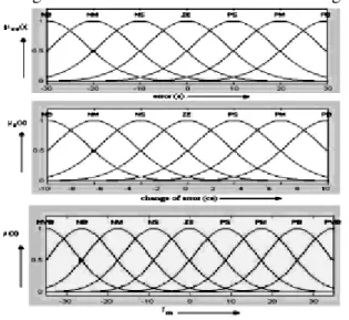
In order to develop the fuzzy-logic control algorithm for APF, two inputs: 1) the voltage error (reference voltage minus actual capacitive voltage, e), 2) the change of capacitive voltage (previous error minus current error; ce) were considered over one sample period. The two inputs were represented by sets of seven membership functions and expressed in linguistic values as negative big (NB), negative medium (NM), negative small (NS), zero (ZE), positive small (PS), positive medium (PM), and positive big (PB). The range for the “error” input was set as[-30,30] and that for “change of error” was set as[-10,10] . A limiting block was introduced before the fuzzy block in order to truncate values beyond these ranges before supplying them to the fuzzy-logic controller. The shape of these membership functions was varied and the effect on the system was studied. The input to the defuzzification process is a fuzzy set (the aggregate output fuzzy set) and the output is a single non fuzzy number, obtained by the center-of-gravity (COG) method of defuzzification. The output (magnitude of reference supply current) is represented by a set of nine membership functions (MFs) (NVB to PVB) whose shape was taken to be similar to the
shape of the input MFs. The range for the output was set as ]. The output of the fuzzy-logic controller was multiplied by a unit sine wave in order to bring it in phase with the supply current before comparison. The AND method used during interpretation of the IF-THEN rules was “min” and the OR method used was “max.” Also, “min” was used as the implication method whereas the “max” method was used for aggregation. The input and output MFs so applied are shown in Fig. 4. The 49 fuzzy IF-THEN weighted rule base was designed to maintain the capacitor voltage constant by providing the required reference current amplitude. Rule generation and weighting were decided based on the pendulum analogy. The resulting rule matrix with assigned weights is shown in Table I.
B. Simulation Results
The PI controller block in the control scheme of the APF was replaced by the designed fuzzy inference system (FIS). The APF was then simulated for the same load with all other parameters maintaining the same. The simulation results for the fuzzy-logic controller designed with Gaussian MFs are shown in Fig 5.
Fig. 4. Gaussian membership function for input
variables
TABLE I. OPTIMAL RULE BASE FOR KPI
NB NS PS PB
NB NM PM PM PM
NS NS NS PB PM
Z ZO NM NM ZO
PS NB PM PM PM
PB PM PM PB ZO
triangular form the uncompensated current is due to current spikes and higher order harmonics.
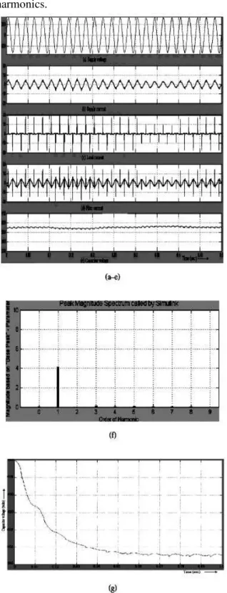
Fig. 5. Dynamic performance of the fuzzy control
scheme with Gaussian MFs for an APF with computer load: (a) supply voltage (V), (b) compensated supply current (A), (c) load current (A), (d) filter current (A), (e) voltage across dc capacitor (V), (f) harmonic spectrum of the compensated supply current, and (g) performance of the fuzzy control scheme with Gaussian MFs for an APF with
the computer load: Transient behavior for a large error in dc-link voltage.
The harmonic spectrum of the compensated supply current is shown in Fig. 5(f). The power factor is improved to 0.9983. It is observed that the capacitor voltage is maintained constant by the FIS. The dynamic response for the addition and removal of the load can be observed from The supply current settles smoothly to a new steady-state value within a quarter cycle of a 50% decrease in load at 0.1 ms and a 200% increase in load at 0.3 ms. The dc-bus voltage settles to its steady-state value within a few cycles. The response of the system for compensating a large initial error of 50 V is also observed. The capacitor voltage reaches the steady-state value without overcompensating or overshooting the set value. The FIS-controlled APF was found to provide better and robust performance under transient and varying load conditions.
V. NEURO-FUZZY ALGORITHM
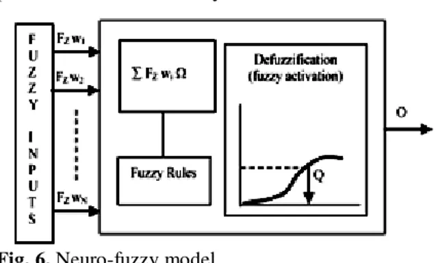
The neural network deals with nonlinear mapping of objective problems and this is a quantitative method of extracting the required information from the raw process signal. The output is given by the equation
Here,Wi represents the connection weights and no set guidelines or rules are present to select these weights.
(ANN) was trained to choose membership parameters automatically.
Fig. 6. Neuro-fuzzy model
The system is modeled by using the Sugeno-type FIS, which is ideal for implementing neuroadaptive learning techniques. In a Sugeno-type system, the output membership functions are either linear or constant.
A typical rule in a Sugeno fuzzy model is given as
The output level “Zi ” of each rule is weighted by the firing strength of the rule. For an AND rule in the aforementioned
case, the firing strength is given by
Wi=AND[F1(x),F2(y)] (8)
WhereF(.)are the membership functions for inputs 1 and 2. The final output of the system is the weighted average of all rule outputs computed as
The Sugeno system is computationally efficient and compact and, hence, was chosen to construct the fuzzy models.
A. Neuro-Fuzzy Control Scheme for APF
The neural network was used to customize the membership
functions so that the fuzzy system best models the control data. In a fuzzy neural system, the neural network essentially implements the functions of a fuzzy system. The first network fuzzifies the crisp input data and the second or
hidden network layer implements the fuzzy rules. Finally defuzzification of the fuzzy output is performed by the third network to provide the crisp data output. The training inputs to the ANFIS are error and change of error, and the training output is the magnitude of the reference current for triggering the active power filter. The neural network was trained to generate an output based on the training inputs such that it closely matches the provided training output. A number of iterations were performed to train the neuro-fuzzy system and the training error was calculated for every iteration.
The training error is given by the difference between training output data and the ANFIS-generated output. An error tolerance limit and epoch number was provided to the ANFIS to conclude the training process when either the training data error is within the tolerance limit or the iteration number exceeds the epoch number. Model validation was accomplished by providing a Checking Data set in order to prevent ANFIS from over fitting the data. In the proposed scheme of developing an ANN-based fuzzy inference system (ANFIS) for control of the active power filter, the following steps were used.
Step 1) Training data: An array containing error values (range ; Step: 0.5), change of error (range ; Step: 0.5), and the output (generated by the Mamdani- type FIS, with 49 rules and Triangular MFs, for the corresponding inputs of error and change of error) were provided as training data.
Fig. 7. ANFIS [5×5] hybrid: (a) Generated input-1
Step 2) Checking Data: An array containing error values (range ]; Step size: 1, change of error (range: ]; Step size: 1) and the output (generated by the Mamdani-type FIS, with 49 rules and triangular MFs, for the corresponding inputs of error and change of error) was provided as checking data. The Sugeno FIS was selected with the most commonly used triangular input MFs. The number of input MFs was taken as five, leading to 25 rules. Constant MFs were selected for output. The hybrid method was applied for training the generated FIS. Training was limited to 1000 epochs and the tolerance limit was set to zero for the training error and checking error. The ANFIS thus generated was tested to control the shunt active power filter. The MATLAB power system and Simulink toolboxes along with the fuzzy-logic tool box were used for simulation.
Neuro-fuzzy FIS with five MFs for each input trained by the hybrid training algorithm generated a 25-rule FIS, whose MFs are shown in Fig. 7(a)–(c). It was observed that the fuzzy partitioning is evenly distributed without discontinuities or irregularities. However, the fuzzy partitions are different than that designed for the 49-rule fuzzy-logic system.
B. Simulation Results
The proposed scheme was simulated using the MATLAB ANFIS editor to design the tuned Sugeno-type FIS, whichwas then used to control the APF by incorporating it in thefuzzy-logic controller block. The system was tested for a fixed as well as a variable load, and the results are shown in Fig. 8. It was observed that the neuro-fuzzy system emulated the fuzzy performance satisfactorily and was computationally more efficient and faster. It was observed that the supply current after compensation becomes sinusoidal with a total harmonic current distortion of 4.89%. The transient response under varying load conditions was found to be the same as that achieved by the fuzzy control system.
VII. DISCUSSION
Traditionally, the design of a control system is dependent on the explicit description of its
mathematical model and parameters. The system can be complex with nonlinearity and parameter variation problems. An intelligent or self-organizing control system can identify the model, if necessary, and give the predicted performance even with a wide range of parameter variations. The conventional PI algorithm for shunt active power filter control assumes the system to be linear and the PI parameters are designed by developing the linearized mathematical model and the Bode or Nyquist plot.
Fig. 8. System results
The designed parameters were found to provide satisfactory performance in terms of harmonic and reactive compensation but when the same system was subjected to a large error, the PI parameters had to be again adjusted to avoid overshoot and overcompensation. Practically, this has to be done by trial and error which is a lengthy and time-consuming process. Soft computing schemes were undertaken with a view to simplify and automate the controller design. These techniques were not considered to be feasible for practical implementation until recently but with the availability of powerful single-chip microcontrollers and digital signal processors, this is no longer an issue.
with Gaussian membership functions gives the desired performance under varying load and supply conditions and is proved to be a better alternative to conventional techniques. It is observed that the filter responds to the changed load conditions within a quarter of a cycle. Though versatile, the fuzzy alternative to conventional PI control was seen to be slow and computationally intense as 49 rules were involved. Despite the advantages of fuzzy control, its main limitations are the lack of systematic procedure for the design and analysis of the fuzzy control system. The heuristic and iterative approach to fine tune the rule base and membership functions can be very time consuming and involved. A few other difficulties in fuzzy control are a lack of completeness of the rule base and a lack of definite criteria for the selection of the shape of the membership functions, their degree of overlapping, the levels of data quantization, and assigning weights to the fuzzy rules. Also, the rule-base method requires defuzzification of the control variable which increases the computational complexity and makes the FIS slow.
The advantage of the flexibility and robustness offered by the fuzzy-logic controller outweighs the limitations and, hence, the neural network was used to overcome these limitations. The neural network was used to identify fuzzy rules and tuning of membership functions. The combined neuro-fuzzy algorithm that was developed retains the advantages of using fuzzy logic but gets rid of the problems involved in designing the FIS by automating the design process. The neuro-fuzzy control algorithm was designed by using the relational approach of fuzzy-logic design, and a reduced rule base with unit weights assigned to the rules. Since there is no need for defuzzification in this method and the design procedure is simplified with only 25 rules instead of the 49 rules in the fuzzy-logic controller, the speed of the FIS increased. Further, it was observed that the two performances are the same.
It was observed that the performance of fuzzy control and, consequently, neuro-fuzzy control is limited by the use of standard membership
functions. The membership function shape is important due to the interdependent relationship between the rule set and the membership function to give the best harmonic compensation over the other schemes.
VIII. CONCLUSION
The overall aim of this paper was to consider methods of achieving better utilization and control of active power filters dealing with harmonic and reactive current compensation. Alternative schemes based on soft computing techniques have been proposed. Nonmodel-based controllers designed around fuzzy logic, neural network were applied to control the switching of the active power filter and were found to provide much better response under varying load and supply conditions.
RESULTS
Pi controller with APF
Fuzzy controller with APF
ANN with APF
REFERENCES
Transactions On Power Delivery, Vol. 24, NO. 1, Jan2009
2. M. El-Habrouk, M. K. Darwish, and P. Mehta, “Active power filters: A review,” Proc. IEEE Electr. Power Appl., vol. 147, no. 5, pp. 403– 412, Sep. 2000.
3. B. Singh, K-Al-Haddad, and A. Chandra, “A review of active filters for power quality improvement,” IEEE Trans. Ind. Electron, vol. 46, no. 5, pp. 960–971, Oct. 1999.
4. W. M. Grady,M. J. Sanotyj, and A. H. Noyola, “Survey of active power line conditioning methodologies,” IEEE Trans. Power Del., vol. 5, no. 3, pp. 1536–1542, Jul. 1990.
5. H. L. Jou, J. C. Wu, and H. Y. Chu, “New single-phase active power filter,” Proc. Inst.
Elect. Eng., Electr. Power Appl., vol. 141, no. 3,
pp. 129–134, May 1994.
6. K. Chaterjee, B. G. Fernandes, and G. K. Dubey, “An instantaneous reactive volt-ampere compensator and harmonic suppressor system,”
IEEE Trans. Power Electron., vol. 14, no. 2, pp.
381–392, Mar. 1999.
7. J. Dixon, J. Contardo, and L. Moran, “DC link fuzzy control for an active power filter, sensing the line current only,” in Proc. IEEE Power
Eng. Soc. Com., 1997, pp. 1109–1113.