ON-LINE CONTROL OF A FLEXIBLE BEAM USING ADAPTIVE FUZZY
CONTROLLER AND PIEZOELECTRIC ACTUATORS
Gustavo Luiz C. M. de Abreu
∗Jos´
e F. Ribeiro
∗ [email protected]∗
Faculdade de Engenharia Mecˆanica, Universidade Federal de Uberlˆandia, Av. Jo˜ao Naves de ´Avila, 2160, Uberlˆandia, MG, 38400-902
ABSTRACT
This paper presents a design of adaptive fuzzy con-trollers applied to the control of vibrations in flexible structures containing distributed piezoelectric actuator patches. The adaptive fuzzy controller is constructed from a set of fuzzy IF-THEN rules whose parameters are adjusted on-line according to some adaptation law. The adaptive law is derived based on the Lyapunov’s stabil-ity theory. This control methodology is experimentally verified in a steel cantilever test beam and a set of ex-perimental tests are made in the system to verify the efficiency of the adaptive fuzzy controller proposed.
KEYWORDS: Adaptive Fuzzy Controllers, Lyapunov’s Stability Theory, Flexible Structures and Piezoelectric Actuators.
1
INTRODUCTION
The great progress experimented by the theory of the fuzzy controllers in the last years has been opening new possibilities of practical application for these controllers.
In the last two decades, the subject area of smart/intelligent materials and structures has experi-enced tremendous growth in terms of research and de-velopment (Crawley & deLuis, 1987). One reason for this activity is that it may be possible to create certain
Artigo submetido em 12/6/2001
1a. Revis˜ao em 4/8/2003
Aceito sob recomenda¸c˜ao do Ed. Assoc. Prof. Takashi Yoneyama
types of structures and systems capable of adapting to or correcting for changing operating conditions. The advantage of incorporating these special types of mate-rials into the structure is that the sensing and actuat-ing mechanism becomes part of the structure by sensactuat-ing and actuating strains directly. This is more known like piezoelectric phenomena, i.e., direct and converse piezo-electric effects. When a mechanical force is applied to a piezoelectric material, an electric voltage or charge will be generated. On the other hand, when an electric field is applied to the material, a mechanical force will be in-duced because of the converse piezoelectric effect. With the recent advances in piezoelectric technology, it has been shown that the piezoelectric actuators based on the converse piezoelectric effect can offer excellent po-tential for active vibration control techniques, especially for vibration suppression or isolation.
Recent research has focused on the applications of piezo-electric sensor and actuator in smart structures. Craw-ley & de Luis (1987) were among the first to embed piezoelectric materials in composite laminated beams. Chen et al. (1996) and Lin et al. (1999) presented a formulation methodology to the control of vibrations in composite structures with bonded piezoelectric sen-sors and actuators. Vibration suppression of composite smart structures by using piezoelectric sensors and ac-tuators were also analyzed numerically by Chou et al. (1997).
and/or accurately determined and that the controller design can be easily implemented. Vibration control of smart structures using fuzzy controllers has thus been receiving attention for their ability to deal with non-linearities, uncertainties in terms of vagueness, igno-rance, and imprecision, and provide a feasible alterna-tive since they can easily capture qualitaalterna-tive aspects of human knowledge. Fuzzy controllers are most suitable for systems that cannot be precisely described by math-ematical formulations. In this case, a control designer captures operators knowledge and converts it into a set of fuzzy control rules. The idea of the fuzzy logic is useful for representing linguistic terms numerically and making reliable decisions with ambiguous and impre-cise events or facts. The benefit of the simple design procedure of a fuzzy controller leads to the successful applications of a variety of engineering systems (Lee, 1990). Zeinoun and Khorrami (1994) proposed a fuzzy logic algorithm for vibration suppression of a clamp-free beam with piezoelectric sensor/actuator, and Ofri et al. (1996) also used a control strategy based on Fuzzy Logic Theory for vibration damping of a large flexible space structure controlled by bonded piezoceramic actuators.
In this work, an adaptive fuzzy controller is constructed from a set of fuzzy IF-THEN rules whose parameters are adjusted on-line according to some adaptation law. The adaptive law is derived based on the Lyapunov’s stabil-ity theory (Wang, 1992). The adaptive fuzzy controller is designed through the following steps: first, construct an initial controller based on linguistic descriptions (in the form of fuzzy IF-THEN rules) about the unknown plant from human experts; then, develop an adapta-tion law to adjust the parameters of the fuzzy controller on-line. We use the Sugeno-type of the fuzzy logic sys-tem to approximate the controller. Finally, the adaptive fuzzy controller is used to control the flexible beam with piezoelectric actuators.
The adaptive fuzzy controllers try to address this kind of problems for three requirements: a) for the first re-quirement, we use nonlinear adaptive control concepts, where nonlinearly is required in order to cover this sys-tems type, and adaptively is required because the math-ematical model of the bonding layer, which bonded the piezoelectrics to an elastic substructure, is unknown; b) for the second requirement, we use fuzzy systems as ba-sic building blocks of the adaptive fuzzy controllers so that linguistic fuzzy IF-THEN rules can be directly in-corporated into the controllers and c) for the third re-quirement, we use the Lyapunov synthesis approach to construct the basic adaptive fuzzy controllers.
This adaptive controller is experimentally verified in a
steel cantilever test beam. A set of experimental tests is made in the system to verify the efficiency of the adap-tive fuzzy controller proposed. Experimental results are shown, to support the effectiveness of the active vibra-tion control, and, finally, a conclusion of this study is given.
2
DESCRIPTION OF THE USED FUZZY
LOGIC SYSTEM
Fuzzy set theory was proposed by Zadeh (1965), and it was employed as an alternative to traditional modeling and control design in order to provide a suitable repre-sentation of complex systems. The basic configuration of the fuzzy logic systems considered in this paper is shown in Fig. 1.
Rule Base
Fuzzification
Interface
Defuzzification
Interface
Decision-making unit
Input Output
(fuzzy) (fuzzy)
(crisp)
(crisp)
Figure 1: Basic Configuration of a fuzzy logic system.
In order to obtain the control design for a nonlinear or complex dynamic system, there are four basic steps in designing a conventional fuzzy logic controller (FLC) for a physical system: 1) the definition of input/output fuzzy variables; 2) the decision making of fuzzy con-trol rules; 3) fuzzy inference logic, and 4) defuzzification and aggregation. The inference operations upon fuzzy if-then rules performed by fuzzy inference systems are described as follows.
The definition of input/output variables. The in-put/output variables of a fuzzy controller can be divided into system variables, and linguistic variables. Most fuzzy controllers employ the error and error rate of sys-tem variables as the input and the force, voltage or an-other variable of the control law as the output.
rules, is composed as follows:
R(m):IF x1 is Am1 and . . . and xn is Amn (1) THEN y=Km
where x = (x1, ..., xn)T and y are the input and the output of the fuzzy logic system, respectively. Am
i is the label of the fuzzy set ini, form=1,2,...,M, andKm is the zero-order Sugeno parameter.
Fuzzy inference logic. The sup-algebraic product com-positional rule of inference is employed in this work.
Defuzzyfication and aggregation. In order to obtain the correct control input for this control system, it is neces-sary to defuzzify the fuzzy sets and aggregate the quali-fied consequent parts to produce a crisp output. In this work, the mean of maximums method is employed to calculate the final output.
Based on these selections, the final output of the fuzzy controller can be calculated by:
y=
K1
n
i=1 µA1
i(xi) +. . .+Km
n
i=1 µAm
i (xi)
n
i=1 µA1
i(xi) +. . .+
n
i=1 µAm
i (xi)
(2)
If we constraint the denominator of the fuzzy system equation (eq. 2) to be equal to 2 by a dynamic scheme, we can rewrite equation 2 as:
y(x) = ΘTΞ (x) (3)
where:
Θ =∆
K1 K2 · · · Km T
and
Ξ (x)=∆
n
i=1 µA1
i(xi)
n
i=1 µA2
i(xi) . . .
n
i=1 µAm
i (xi)
n
i=1 µA1
i(xi) +. . .+
n
i=1 µAm
i (xi)
T
Here, Θ represents the vector of adaptation parameters and Ξ (x) vector of regressors.
3
DERIVATION
OF
THE
ADAPTIVE
FUZZY CONTROLLER
Consider thenth-order nonlinear systems of the form
x(n)=fx,x, . . . , x˙ (n−1)
+bu
y=x (4)
where f is an unknown but bounded continuous func-tion,bis a positive unknown constant, anduandy are the input and output of the system, respectively.
The control objective is to force y to follow a given bounded reference signalym under the constraints that all signals involved must be bounded. Hence, a feedback controlubased on fuzzy logic systems and an adaptive law for adjusting the parameters of the fuzzy logic sys-tems are both determined to satisfy the following con-ditions:
• The closed-loop system must be globally stable and
• The tracking errore =ym−y should be as small as possible under the constraints in (4).
The design objective is to impose an adaptive fuzzy con-trol algorithm so that the following asymptotically sta-ble tracking:
e(n)+k1e(n−1)
+. . .+kne= 0 (5)
is achieved. The roots of polynomial in the characteristic equation of (5) are all in the open left-half plane via an adequate choice of coefficientsk1, k2, . . . , kn.
We firstly show the design of an optimal control system based on the assumption that the system equations are completely known. The optimal control law is:
u∗
= 1
b
−f(x) +(yn)+kTe (6)
Since the roots k1, k2, . . . , knare in the left-half plane, the equation 5 implies that limt→∞(e(t)) = 0. Now,
since the system is unknown, we can not implement the optimal control law (eq. 6). We want to design an adap-tive fuzzy control system to approximate this optimal control.
Let uf(x|Θ) be an adaptive fuzzy control law in the form of:
uf(x|Θ) = ΘTΞ (x) (7)
Substitutinguf(x|Θ) into equation 4 we have:
˙
x=f(x) +buf(x|Θ) (8)
By adding and substractingbu∗
to equation 8 we obtain the error equation governing the closed-loop system:
˙
where Λc=
0 1 0 . . . 0
0 0 1 . . . 0
..
. ... ... . .. ... 0 0 0 · · · 1
−k1 −k2 −k3 . . . −kn−1
, bc = 0 0 .. . 0 b (10)
Now, defineVe= 12eTP ewhere P is a symmetric posi-tive definite matrix satisfying the Lyapunov equation:
ΛTcP+PΛc=−Q (11)
whereQ >0. Using equation 11 and the error equation 9, we have:
˙
Ve=−12eTQe+eTP bc(u∗−uf(x|Θ))
−1
2eTQe+
eTP bc
(|u
∗
|+|uf(x|Θ)|) (12)
Then, we replace the uf(x|Θ) by the fuzzy inference sys-tem 7 and develop an adaptive law to adjust the param-eter vector Θ. We define the optimal paramparam-eter vector:
Θ∗∆
= arg min
Θ (sup|ε|) (13)
whereεis defined asε∆=uf(x|Θ∗)−u∗, the control error. The error equation 9 can be rewritten as:
˙
e= Λce+bc(uf(x|Θ∗)−uf(x|Θ))−bcε = Λce+bcΦTΞ (x)−b
cε (14)
where Φ= Θ∆ ∗
−Θ and Ξ (x) is the vector of regressors in equation 3. Now, define the Lyapunov function can-didate:
V = 1 2e
TP e+ b 2γΦ
TΦ
whereγ is a positive constant. Using equations 14 and 11 we can derive:
˙
V =−1
2e
TQe+eTP b
cΦTΞ (x)−ε+
b γΦ
T ˙Φ (15)
Now, let pn be the last column of P, then from the equation 10 we have:
eTP bc=eTpnb (16)
Substituting equation 16 into 15, we obtain:
˙
V =−1
2e
TQe+ b
γΦ
TγeTp
nΞ (x) + ˙Φ
−eTP bcε
(17)
If we choose the adaptive law as:
˙
Θ =γeTpnΞ (x) (18)
and using the fact that ˙Φ =−Θ, equation 17 becomes:˙
˙
V −1
2e
TQe−eTP b
cε (19)
which is the best we can achieve.
In summary, using the adaptation law given by eq. 18, we can guarantee that ˙V <0.
4
IMPLEMENTATION OF THE
ADAP-TIVE FUZZY CONTROLLER
Briefly, the adaptive fuzzy controller is designed as fol-lows:
1. Initialization phase: To ensure stability, fix the
con-troller parameterskandQas discussed earlier, and solve equation 11 to obatin P >0.
(a) Specify a set of fuzzy rules
(b) Set initial conditions (i.e. relative Sugeno pa-rameters, ΘT
0).
2. Online phase:
(a) Adjust relative zero-order Sugeno parameters of rules by using the online adaptation algo-rithm of equation 18 in the following form:
ΘT
t+1= ΘTt +γeTpnΞ (x)dt (20)
where t is the actual time and dt is the sam-pling time.
Using equation 7 calculate the new control using the new parameter ΘT
t+1, as calculated in step above.
5
CONTROL PROBLEM FORMULATION
In this section, we apply the adaptive fuzzy controller to control a flexible structure using piezoelectric actuators.
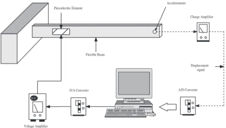
Figure 2: Experimental apparatus.
These piezoelectric elements are fed by a voltage am-plifier (provide by company ACX), that amplifies the entrance voltage in the order 30 V/V.
The flexible structure which is 400 [mm] long and has a cross-sectional dimensions of 34.5 x 1.2 [mm], con-tains two piezoelectric patches having a cross-sectional dimensions of 20.574 x 0.254 [mm] and its length is 46 [mm].
Each pair of piezoceramics (PZT) is bonded side by side to form two sets of actuators located 92.93 [mm] of the rigid support.
The schematic diagram for the vibration suppression ex-periment is shown in Figure 3. One accelerometer (B&K 4375) attached at the tip through the charge amplifiers is used to measure the system displacement with inte-gration circuits. Since the output voltage of the interface board is limited to±5 [V], a voltage amplifier (ACX) is needed to drive the actuator in the range of ±150 [V] for effective control performance.
According the schematic diagram shown in Figure 3, the accelerometer signal is read by the A/D converter that communicates with a microcomputer (used in the implementation of a processing digital system using the adaptive fuzzy control algorithm). The sampling time used was 3 miliseconds.
For the verification of the adaptive fuzzy controller pro-posed we present a set of experimental tests for the sys-tem without control and controlled.
We set the referenceyref = 0 and design the adaptive fuzzy controller:
1. Initialization phase:
;;
ACX
A/D Converter D/A Converter
Charge Amplifier Accelerometer Piezoelectric Element
Voltage Amplifier
Flexible Beam
Displacement signal
Figure 3: Schematic diagram of the vibration control experiment.
(a) We define k =
3 2
, Q = diag(5,5). Then, we solve (11) and obtain P =
5 2.5 2.5 2.5
.
(b) The fuzzy controller presents two inputs: er-ror and change-of-erer-ror and one output: the output voltage applied to the voltage ampli-fier. We define membership functions (gauss-shaped) of 3 fuzzy sets (Negative –N,Zero –
Z and Positive – P) for the linguistic values of the input variables and the cross-point ratio of all is 0.5. The ranges of the input variables are defined as: error: -1.5 to 1.5 [mm] and change-of-error: -0.02 to 0.02 [mm/s].
The base of rules was composed by 9 rules and is given by Table 1.
Table 1: Base of rules.
Change-of- error
N Z P
N 1K1 2K2 3K3
Error Z 4K
4 5K5 6K6 P 7K
7 8K8 9K9
where
K1 K2 · · · K9 T
is the vector of adaptation parameters.
Each one of the cells represents one rule con-structed in the following form:
R1 : If error is N and change-of-error is N
then
output voltage isK1
(c) Set ΘT
0 =
0 0 · · · 0 T
andγ= 100. Online phase as described in section 4.
0 2 4 6 8 10 12 14 16 18 20 -5
0 5
Tempo (s)
Deslocamento (mm)
Time (s) Displacement (mm)
Figure 4: Experimental open-loop response.
0 0.5 1 1.5 2 2.5 3 3.5 4 4.5 5 -5
0 5
Time (s) Displacement (mm)
Figure 5: Experimental close-loop response.
the period of 0.5 [s] and after this time they were utilized to control the flexible structure (see Fig. 6). The Figure 4 and 5 show the experimental open-loop response and close-loop response, respec-tively. The results clearly demonstrate the effec-tiveness of the adaptive fuzzy controller approach which achieve lower settling time.
The Figures 6 and 7 show the temporal evolution of output voltage applied to voltage amplifier and Sugeno parameters, respectively. The Sugeno pa-rameters achieved are given in Table 2.
0 0.5 1 1.5 2 2.5 3 3.5 4 4.5 5 -5
0 5
Output Voltage (V)
Time (s)
Figure 6: Output voltage response applied to voltage amplifier.
0 0.5 1 1.5 2 2.5 3 3.5 4 4.5 5 -3
0 3
Time (s) Sugeno Parameters
1 K
2 K
3 K
4 K
5 K
6 K
7 K
8 K
9 K
Figure 7: Temporal evolution of Sugeno parameters.
6
CONCLUSIONS
An adaptive fuzzy controller implemented in real-time was developed to control the vibrations of the flexible beam type structure using piezoelectric actuators. The results were presented for a simply cantilever steel
flex-Table 2: Final base of rules.
Change-of- error
N Z P
N 2,787 -0,003 -2,247
Error Z 2,167 0,050 -1,960
ible beam. By using a Lyapunov synthesis approach we expect to synthesise a stable adaptive system. The ex-perimental results presented show that the present con-trol methodology is effective and the concon-trol behaviors exhibit our predicted characteristics. From the exper-imental test results, it is concluded that the proposed design achieves the desired results.
The experimental results have shown that piezoceramic actuators bonded on a beam control efficiently the vi-brations of this flexible structure. Work is in progress to use piezoelectric PVDF film materials as displacement sensors instead accelerometer.
REFERENCES
ACX,ActiveControl eXperts,Inc. All rights reserved, http://www.acx.com.
Chen, Chang-qing; Wang, Xiao-ming, and Shen, Ya-peng (1996). Finite Element Approach of Vibration Control Using Self-Sensing Piezoelectric Actuators,
Computers & Structures, Vol. 60, No. 3, pp.
505-512.
Chou, Jyh-Horng; Chen, Shinn-Horng; Chang, Min-Yung, and Pan, An-Jia (1997). Active Robust Vi-bration Control of Flexible Composite Beams with Parameter Pertubations, International Journal of
Mechanical Science, Vol. 39, No. 7, pp. 751-760.
Crawley, E. F., and De Luis, J. (1987). Use of Piezoelec-tric Actuators as Elements of Intelligent Structures,
AIAA Journal, Vol. 25, No. 10, pp. 1373-1385.
Lee, M. (1990). Fuzzy Logic in Control Systems: Fuzzy Logic Controller – Part I and II,IEEE Transactions
on Systems, Man and Cybernetics, Vol. 20, No. 2,
pp. 404-435.
Lin, Chien-Chang, and Huang, Huang-Nan (1999). Vi-bration Control of Beam-Plates with Bonded Piezo-electric Sensors and Actuators, Computers and
Structures, Vol. 73, pp. 239-248.
Ofri, A.; Tanchum, W., and Guterman, H. (1996). Ac-tive Control for Large Space Structure by Fuzzy Logic Controllers,IEEE, pp. 515-518.
Zadeh, L. A. (1965). Information and Control, Vol. 8, pp. 338-353.
Zeinoun, I. J., and Khorrami, F. (1994). An Adaptive Control Scheme Based on Fuzzy Logic and its Ap-plication to Smart Structures,Smart Mater. Struc., Vol. 3, pp. 266-276.
Wang, Li-Xin (1992). Stable Adaptive Fuzzy Control of Nonlinear Systems, Proceedings of the 31st
Con-ference on Decision and Control, Tucson, Arizona,