Integrated Applications with Laser Technology
Octavian DOSPINESCU1, Paul BRODNER2
1Faculty of Economics and Business Administration, AL.I.Cuza University, Iasi 2OSF Global Services
[email protected], [email protected]
The introduction of new materials as Power Point presentations are the most convenient way of teaching a course or to display a scientific paper. In order to support this function, most schools, universities, institutions, are equipped with projectors and computers. For control-ling the presentation of the materials, the persons that are in charge with the presentation use, in most cases, both the keyboard of the computer as well as the mouse for the slides, thing that burdens, in a way, the direct communication (face to face) with the audience. Of course, the invention of the wireless mouse allowed a sort of freedom in controlling from the distance the digital materials. Although there seems to appear a certain impediment: in order to be used, the mouse requires to be placed on a flat surface. This article aims at creating a new application prototype that will manipulate, only through the means of a light-beam in-strument (laser fascicle), both the actions of the mouse as well as some of the elements offered
by the keyboard on a certain application or presentation. The light fascicle will be „connec
t-ed” to a calculus system only through the images that were captured by a simple webcam.
Keywords: Surface Emitting Lasers, Technology Management, Software Prototyping, Optical Recognition Software
Introduction
We are now in the information and knowledge age and the ways data can be pre-sented are very different [1]. The laser point-ers are usually used to attract the attention on some important aspects within the presenta-tion. They also were incorporated in wireless mice, but using such an instrument offers on-ly a simple navigation control and it cannot be used for some more complex applications. The functional requirements aim at the sim-plification of the interaction between man-machine (computer), especially with the help of a webcam and with the help of a laser de-vice. The application will be installed on any computer that has a webcam. Other than a webcam, the user has to have a laser device (laser pointer, or any other powerful light fascicle). Once launched, the application will „read” through the webcam the images that were captured from a certain location that was previously established (example: at a presentation where it is used a projector). Through the means of some processing algo-rithms on the captured images, the action de-veloped by the movement of the laser point on the board, will be transmitted to the
com-puter, more exactly to the mouse. In other words, the application will use only one laser device that will allow the user to control the movement and the actions of the mouse from a far distance.
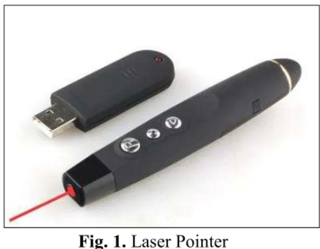
Fig. 1. Laser Pointer
The general operational way can be synthe-sized in the following important steps:
The user is the one that will start the ap-plication and who will initialize the main way, meaning the verification of the ex-istence of a webcam, the installation of the specific drivers of the webcam, read-ing the configuration files;
Starting the webcam will automatic initi-ate the capturing of the images (if this op-tion was marked by the user). At this moment will be launched two wires of execution: after the processing of the im-age by the webcam, a web framed is saved as an image.
The captured frame is submitted to opti-mization algorithms for making more ef-fective the detection process of the laser point.
The Laser Module will instantiate the de-tection process of the light fascicle, which through the means of some algo-rithms will give back and it will graph-ically display the location of the laser fascicle; moreover the mouse of the com-puter will be repositioned at a new coor-dinate.
The Mouse Module is the one that will control the actions developed by the laser point, the actions of the mouse as well as the contextual graphic menu.
The application will interact with any other program that is installed on the computer. Some specific gestures could be memorized by the application, in order to use a certain order (for example: if the laser point will move to the right in the upper part of the board (N-E) Microsoft Office Outlook will open) as well as the various actions of the mouse: single/double left/right clock, saved settings in a configuration file.
2 Hardware configuration and software development
Regarding the hardware resources that are concerned, the prototype proposed is com-posed from the following:
Laptop or PC having as operating systems Windows XP/VISTA/7 (the other operat-ing systems were not tested);
Fig. 2. Laptop/computer
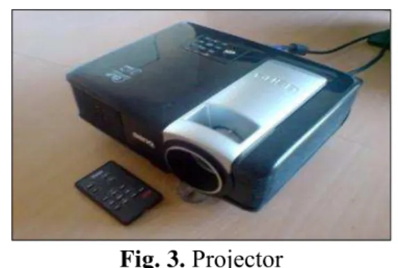
A projector that has to be connected to the
computer (is an optional instrument; the application may work even if this device is missing);
Fig. 3. Projector
Integrated webcam or a webcam
connect-ed through a USB (the application offers the possibility to choose one of the availa-ble cameras);
Fig. 4. Webcam
A laser pointer
Fig. 5. Laser pointer
3 Implemented System
Through this paper we aim at presenting the determination algorithm of the existence of a laser fascicle from a given image. In our way we decided that the control instrument of the mouse to be a LASER (Light Amplification by Stimulated Emission of Radiation) be-cause of the special characteristics that it holds [2], [3]:
It is monochromatic: the wave length
presents only one color. Even though some lasers may generate various wave lengths, the emitted light is very pure be-ing composed from one color of the visu-al specter.
It is directed: traverses a big distance on one trajectory.
It is coherent: has the same wave length
and a constant phase in time.
It is necessary to understand the operational process of a laser in order to develop valid algorithms. In what the mono-chromatisation of the light fascicle is concerned, the color is determined by the frequency or by the wave length. The smaller wave lengths are the ul-traviolet ones (under 400 nanometers -nm) but these are not visible for the human eye, in other words they are not in the visible elec-tromagnetic specter. The human eye is able to distinguish length waves on a scale from 390 and 750 nm, according to [4]. This spec-ter does not have all the colors that the hu-man eye can see. Figure 6 shows the colors that are visible for the human eye according to the wave length.
Fig. 6. Visible linear specter of color on wave lengths (nm)
Knowing this information, an efficient meth-od is the detection of the laser fascicle that is based on one of its characteristics: emitted color (monochromatic). Being given a certain image, the light point (Red, Green) may be easily detected; Bowden [5] even explains in his paper some methods of object detection, movement detection, being used the captured colors.
If we take into account the fact that our ap-plication is developed especially for presen-tations, where there are used a various range of colors, this solution is not a very conven-ient one. In order to solve this problem it was taken into account the light offered by the la-ser point. In conditions of different shades of light, it was noticed that the point of the laser has always the highest brightness in an im-age.
An image represents a replica of an object and it is considered to be a function of two real variables x and y [6]. It is composed from many points or pixels [7] - the smallest component of a digital image that may be
controlled or modified. Each pixel has an ad-dress that corresponds with a coordinate and represents a very small part from the whole picture (it is like in the case of puzzles). The-se pixels are characterized through position, intensity and time (in case of films). In all the combinations these parameters define the static images or the video clips. As long as there are used more pixels (high resolution), the final image will look more realistic. And therefore we get to the main characteristic in the case of solving our algorithm. The num-ber of distinct colors may be represented by a pixel, depends on the number of bits on the pixels (bpp – bits per pixel):
An image with 1 bpp will use only 1 bit for each pixel, therefore each pixel will beat a certain point 1 or 0. Each bits add-ing will enlarge the number of available colors.
An image with 2 bpp will have 4 colors (2
Our algorithm will be applied to our images with 24 bpp, meaning 16.8 million colors. Therefore, for an efficient manipulation of the information that exists in an image, it was decided that the keeping of the pixels to be saved in the memory under a one-dimensional matrix. All the information of an image – both on the X as well as on the Y ax-is – will contain all the pixels that form the length/width of the image. These pixels are saved like numbers from 0 to 255, meaning colors like Red, Green, Blue, as well as their opacity.
Brightness = (299 * Red + 587 * Green + 114 * Blue) / 1000
According to W3C [8], the brightness can be calculated according to the RGB (Red/Green/Blue) of a pixel from an image, with the formula from above. Also, it is very important to detect the right position of every pixel [9]. Further on we will present a small example in order to describe the algorithm: the figure from below presents the infor-mation of all the pixels of a static image.
Fig. 7. The information of the pixels of an image saved in an array
As it can be seen, this array has 12 columns and 3 lines but the color of a pixel is repre-sented by 3 cells (RGB) therefore the first 3 cells (2, 112 and 223) are the colors of the first pixel, (0,101 and 255) of the second pix-el, and so on. The problem consist in the fact that all the information is saved in a one-dimensional array and its course will be done from the first position (2) up to the last (219) not taking into account the length or the width.
On the basis of the previous mentioned for-mula, we will calculate the most powerful brightness of the existing pixels, using also the ColorMatrix class [10], [11]. If we will find a n number of pixels with a brightness higher than 241 (an initial value that can be modified by the user; the most powerful brightness = 255, the smallest = 0) we will keep the current position of the pixel in the one-dimensional array. Example: if the pixel (112, 223, and 245) is the brightness, its po-sition will be kept (15).
Fig. 8. Pixels and adjacent positions in the same order like they are saved in the
one-dimensional array
According to this information and taking into account the fact that the width of the 12 pix-els image, the coordinates of the cell can be
Fig. 9. Computing the coordinates
The practical implementation of the theoreti-cal notions from above is presented in the listing from below, using a Visual Basic
.NET implementation based on several rules [12], [13], [14]:
Private Function GetX(ByVal nrCelula As Integer, ByVal mX As Integer) As Integer Dim resX As Integer
If nrCelula <= mX Then resX = mX - nrCelula ElseIf nrCelula > mX Then resX = nrCelula - mX End If
If resX > mX Then
Return GetX(resX, mX) ElseIf resX = mX Then Return mX - 1 ElseIf resX < mX Then Return resX End If
End Function
Sub CapturaImagine(ByVal panou As Form, ByVal e As PaintEventArgs) Dim tX, tY As Integer
tX = tY = 0
'save the initial image
mImagineVeche.PrintScreenImagine(panou) 'apply filters to the original image mImagineVeche.AplicaFiltru(Filtru.Gri)
'save image in am array (by the method Marshal.Copy -> in a local array) mImagineVeche.BlocheazaImagine()
'initialize the new image
mImagineNoua.CopieValoriInitiale(mImagineVeche) 'a new bitmap data
mImagineNoua.BlocheazaImagine() mContorLaserPuncteDetectabile = 0
For iCounter = 0 To mImagineVeche.ImageByteArray.Length - 3 Step 3 'computing the lightness of every pixel (RGB)
If (mImagineVeche.ImageByteArray(iCounter + 2) * 299 + 587 *
mImagineVe-che.ImageByteArray(iCounter + 1) + 114 * mImagineVemImagineVe-che.ImageByteArray(iCounter)) / 1000 >= mLuminozitate Then
mContorLaserPuncteDetectabile += 1
If mContorLaserPuncteDetectabile > mImagine-Noua.PunctLaser.NrPuncteFascicolLaser Then GoTo AplicaCuloareFiltru
'all the pixels have red color
mImagineVeche.ImageByteArray(iCounter) = 0 ‘blue
mImagineVeche.ImageByteArray(iCounter + 1) = 0 'green
mImagineVeche.ImageByteArray(iCounter + 2) = 255 'red
mImagineNoua.ImageByteArray(iCounter) = 0 'blue
mImagineNoua.ImageByteArray(iCounter + 1) = 0 'green
mImagineNoua.ImageByteArray(iCounter + 2) = 255 'red
Dim pozitie As Integer pozitie = iCounter / 3
ix = GetX(pozitie, mImagineNoua.Imagine.Width) 'strides iy = pozitie / mImagineNoua.Imagine.Width
‘a new tracker for Laser with the new x,y position
mImagineNoua.PunctLaser.Locatie = New Point(ix - 5, iy - 6) 'show information
mPanouInformatii.ValX = ix.ToString mPanouInformatii.ValY = iy.ToString
mPanouInformatii.ValStrides = iCounter.ToString Else
AplicaCuloareFiltru:
If mCuloareFiltru <> CuloareFiltru.AlbNegru Then
mImagineVeche.ImageByteArray(iCounter + mCuloareFiltru) = 255 End If
End If Next
'save the changes from the arrays into bitmaps mImagineVeche.SalveazaModificariPixeli()
mImagineNoua.SalveazaModificariPixeli() 'clear the memory
mImagineVeche.DeblocheazaImagine() mImagineNoua.DeblocheazaImagine() 'drawing only the old image mImagineVeche.DeseneazaImagine(e) End Sub
The above algorithm will calculate, accord-ing to brightness, the fascicle from an image. Of course, these calculations will be done in a very short time (according to the power of calculation of the computer) for each im-age/frame captured by the webcam. The new image will be displayed to the user only with the graphic representation of this point.
4 The Interface of the Application and Fu-ture Directions
The interface of the application has the fol-lowing main functions:
1.1 – selecting an available webcam;
1.2 – pushing the video capture button. In
this moment the secondary form will display each frame separately.
2.1 – once the webcam starts, the
optimiza-tion/filtration algorithm as well as the algo-rithm of detection of the laser fascicle are applied to the captured frames from the sec-ondary form.
2.2 – the user may choose an image filtering
color;
3.1 – activate the display option of the
con-textual menu of the mouse;
3.2 – the new image with the laser fascicle
Fig. 10. The application interface
When the application is on, its control will be taken by the light fascicle (meaning the laser pointer). Keeping the laser fascicle only for a few seconds at a certain coordinate will have as an effect the activation of the contextual menu. In the testing phase of this prototype, it was noticed that it is necessary a new in-tervention on the algorithm in order to offer a
more accurate control to the user. This prin-ciple was carefully analyzed because it is de-sired for the user to control the application and not the other way around.
Therefore, if the laser fascicle is pointed to-wards a certain point, the algorithm will de-tect the new position and it will graphically display the new point.
This change of the coordinate will be applied to the mouse according to the width/height of the active monitor (resolution).
4 Conclusions
The integration of the information technolo-gies is one of the starting points for the future systems. As we could see in this paper, the hardware and software integration can gener-ate new features for the final users. We in-tend to develop the present prototype and to implement a better control of the laser fasci-cle by processing the light color and so we want to diversify the possibilities of the ap-plication control.
References
[1] M. Draganescu, “Perspectivele societatii cunoasterii in Romania”, 2010. [Online]. Available:
http://www.racai.ro/~dragam/AGIR2.pdf [2] V. Letokhov, C. Abitbol “Progress in op-tics”, Volume 16, Emil Publishing House, Wolf, North-Holland, 2001, p. 239
[3] R. Aldricht, “Laser Fundamentals”, 2012.
[Online]. Available:
http://www.fas.org/man/dod-101/navy/docs/laser/fundamentals.htm#L
ASER%20
THEO-RY%20AND%20OPERATION
[4] T. Bruno, D.N. Svoronos, “CRC Hand-book of Fundamental Spectroscopic Cor-relation Charts”, CRC Press, Colorado, USA, 2005
[5] R. Bowden, “Learning Non-linear Mod-els of Shape and Motion. Enhancing tracking using colors”, 2011. [Online]. Available:
http://info.ee.surrey.ac.uk/Personal/R.Bo
wden/publications/thesis/download/chapt er4.pdf
[6] P. Sudhir, “Seminar of „Image Processing”, Gyan Vihar School of Engi-neering & Technology, 2008
[7] J. A. King, “Digital Photography for
Dummies”, 5th Edition, Wiley
Publishing, Canada, 2005
[8] W3C, “Techniques for Accessibility Evaluation and Repair Tools”, Working Draft, accessed august 2010. [Online]. Available: http://www.w3.org/TR/AERT [9] M. Combs, “Color Matrix Basics – Sim-ple Image Color Adjustment”, 2003.
[Online]. Available:
http://www.codeproject.com/KB/GDI-plus/colormatrix.aspx
[10] Microsoft Corporation, “Color Matrix Class”, 2012. [Online]. Available:
http://msdn.microsoft.com/en-us/library/system.drawing.imaging.color matrix.aspx
[11] B. Powell, “How to convert a color image to grayscale”, 2011. [Online]. Available:
http://www.bobpowell.net/grayscale.htm [12] Microsoft Corporation, “Lock Bits
Method”, 2012. [Online]. Available:
http://msdn.microsoft.com/en-us/library/5ey6h79d.aspx
[13] Microsoft Corporation, “Unclock Bits Method”, 2011. [Online]. Availa-
ble:http://msdn.microsoft.com/en-us/library/system.drawing.bitmap.unlock bits.aspx
[14] Microsoft Corporation, “Bitmap and Image constructor dependencies”, 2012. [Online]. Available: http://support. mi-crosoft.com/kb/814675/en-us
Octavian DOSPINESCU graduated the Faculty of Economics and Business
Trade&Inventory Module. He is interested in mobile devices software, computer program-ming and decision support systems.
Paul BRODNER graduated the Faculty of Economics and Business