95
Microcontroller Based Data Acquisition And
Supervision
Ishaan Dua, Prerna Choudhary, Shubham Soni, Sheila Mahapatra
ABSTRACT: In this research paper we have designed a system that acts as a temperature sensor and also a warning system the system also has the facilitation of shutting down the machinery whose temperature is to be monitored. The main function of the system is to constantly monitor the temperature of a machine, compare it to a predefined limit and shut down the machine if the temperature exceeds or falls below that limit. The system is highly useful for systems with high dependence on particular temperatures. The paper includes the requirement of such a system along with the idea behind development of the project. We have covered the hardware and software requirements for designing such a system. The paper covers the basic design of the project along with the block diagram. We have divided the entire design into sub circuits that cover the bridge rectifier, relay driver and A to D convertor. We have covered the software simulation of the sub circuits. The results of the simulations have been compared to the expected outcome and so we know that the design is working properly.
Index Terms: analog, digital, microcontroller, sensor, shutdown, temperature, tansmission
————————————————————
INTRODUCTION
Now a days manufacturing processes have become highly automated and it is the need of the hour. Amongst the automation processes is one highly integral process is of temperature control. A lot of manufacturing processes involve works to be done at a particular temperature. If it is not controlled then the entire process may go to waste. This paper is going to cover a system that can be used as a solution for such processes. The paper is based on a
system by the name „TEMPERATURE SENSOR AND WARNING SYSTEM‟. This system is designed to sense the
temperature of a surface of a machine compare it with a limit that has been pre-set by the manufacturer and if it exceeds the limit then to warn and shut down the machine. This setup is also interfacing with a computer wirelessly and so it is not necessary that a controller needs to be directly besides the machine. The machine that needs to be controlled can be situated in a remote area just with the system installed on its surface and the controller can be in a different location controlling it via his computer. This system when implemented on a large scale can become a part of SCADA system as we are acquiring data as well as controlling it. If it is used as a part of SCADA then we will have to include plc programming as well. Since data is being transmitted through a wireless channel it is essential to know what is WIRELESS SCADA.
WIRELESS SCADA
We need to understand what SCADA is and why are we using wireless system. SCADA stand for Supervisory Control and Data Acquisition. It is a system that allows us to monitor data and control processes that are spread over various remote sites. A well designed SCADA system will help us save time and money by eliminating the requirement of a visit for inspection and data collection or making any adjustments. In case of a wireless system the transmission of data/signal is done over a radio channel or through a gprs mobile phone. The need for wireless system arises due to conditions of the area and also cost of transmission. If the machine that is to be controlled is located remotely and the main controller is at a different region that is far then transmission through cables would be very expensive as compared to wireless transmission. Secondly laying down of the cable is a time consuming process thus it is viable to use a wireless system. The main components of a wireless SCADA system are:
MASTER UNIT- it is the main component and is under direct control of the operator.
REMOTE UNIT- it is installed where the process is being done. It collects all the data required and transmits it to the master unit.
COMMUNICATION MODE- this unit is used to transmit the data or signals between the remote unit and master unit.in our system it is wireless
SOFTWARE- this acts as a machine user interface. It also provides a visual approach for the operator controlling the process.
PROBLEM FORMULATION
The idea behind our project was the problems with hydraulic presses. In the line of slipper manufacturing the sole of slippers is made by cutting out the sole from large sheets of rubber. The rubber is actually made in hydraulic presses where hot oil flows through the plate of the press. It is essential that the temperature of the plate to be maintained between 90-140 degree centigrade. If it is not maintained at this level then the properties of rubber like elasticity, softness and colour changes which is highly undesirable. This paper will give the results of the software implementation of a design of a system that will be useful for control of such processes.
__________________
Author ishaandua is currently pursuing his bachelors degree program in electrical and electronics engineering from ITM University , India
Co- Author PrernaChoudhary is currently pursuing her bachelors degree program in electrical and electronics engineering from ITM University , India Co- Author ShubhamSoni is currently pursuing his
bachelors degree program in electrical and electronics engineering from ITM University , India Co- Author Sheila Mahapatra is a professor in
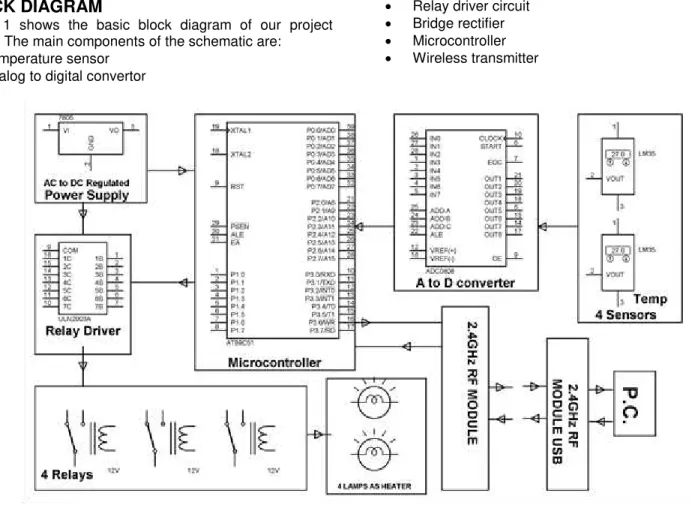
BLOCK DIAGRAM
Figure 1 shows the basic block diagram of our project design. The main components of the schematic are:
Temperature sensor
Analog to digital convertor
Relay driver circuit
Bridge rectifier
Microcontroller
Wireless transmitter
FIGURE 1- BLOCK DIAGRAM
WORKING
The main aim of our project is to monitor and control real time data acquisition wirelessly. The various steps involved in the working of our project are as follows.
The temperature sensors are mounted to the surface whose temperature is to be monitored.
Upon sensing the temperature it sends the signal to ADC 0808. This is the analog to digital convertor used. It converts the signal received from the sensor into digital format that can be read by the microcontroller. The convertor feeds its output into the microcontroller.
The microcontroller being used here is AT80C51. All these devices cannot run on high voltage and therefore to us this controller we need to get 5 volt power supply.
This is done by the bridge rectifier. It firstly converts ac to dc and secondly steps down 220v to 5v and gives this supply to the controller.
The controller performs 3 main functions. They are as follows:
o Comparing values received from the ADC to
predefined limits
o Running the relay driver which is used to
switch off the machine
o Generating the required frequency to be used
for wireless transmission.
Once the microcontroller receives the signal from the ADC it compares it to a pre-set limit.
If the temperature lies between that limit then no action is taken.
If the temperature exceeds that limit or falls below it then the controller sends a signal to the relay driver circuit to shut down the machine.
All the communication with the operator is done wirelessly through a RF 2.4GHz transmission module.
SOFTWARE IMPLEMENTATION
The software implementation was performed on a software by PROTEUS and the software name was ISIS. This software enables us to build circuits with a variety of microcontrollers to choose from and the library of elements is huge. This simulates the modelled circuit in real time and shows real time outputs. To perform the simulation we divided the entire circuit into 3 sub- circuits which are:
Analog to digital convertor
Bridge rectifier
Relay driver
ISIS SOFTWARE
97
conditions and lets him know whether the design will work according to his needs or not.
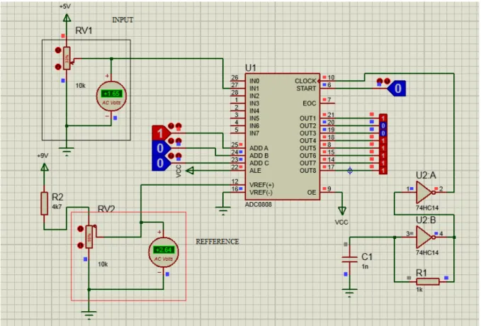
Analog to Digital convertor
Figure 2 shows the circuit for the analog to digital convertor. Over here we have two main parts. The circuit is converting the analog signal into a digital form and also comparing are
input with the reference signal as set by us. We can see in the figure the portion with the black outline is the input and the portion with the red outline is the reference. The address lines are present to select which input pin will be selected and to select the pins the following table can be used.
Figure 2- A TO D CONVERTOR
Selected analog channel Address line
C B A
IN0 LOW LOW LOW
IN1 LOW LOW HIGH
IN2 LOW HIGH LOW
IN3 LOW HIGH HIGH
IN4 HIGH LOW LOW
IN5 HIGH LOW HIGH
IN6 HIGH HIGH LOW
IN7 HIGH HIGH HIGH
Table 1
Here L and H stand for low and high respectively and by giving the respective input on the address lines the required inputs can be selected. Over here the reference voltage is the resultant voltage that will be generated by the temperature limit set by us and the input voltage will be generated by the temperature sensors. It is observed
BRIDGE RECTIFIER
FIGURE 3- BRIDGE RECTIFIER
The bridge rectifier circuit is another essential circuit as it performs the function of converting the AC to DC and also steps down the voltage from a high magnitude of 220 volts to a magnitude of 5 volts. The schematic of the circuit is given in FIGURE 3. This conversion is very necessary as the devices being used here cannot sustain high voltages and if they are given voltages with high magnitudes it can cause the device to get damaged. The rectification is being done by the diodes connected. It is seen from the simulation that once a bulb is connected to the circuit we can see the circuit is working properly as the bulb starts to light.
RELAY DRIVER CIRCUIT
The relay driver circuit is given in figure 4. The input is given to the IC ULN2003A. This IC acts as an inverter and if we give a high input then output is low and vice versa. Thus when we give a low output there is no potential difference and so the circuit does not perform any action however on giving a high output there is a potential difference which makes the relay generate an electric field and allows it to switch between ports. The main function of the relay driver is to cut off supply to the machine if the temperature is going outside the limits set by controller
99
WIRELESS TRANSMISSION
Wireless transmission is done with the help of a RF 2.4 GHz module that has a transmitter attached to the system and a receiver which is connected to our computer. The wireless transmission helps in reducing the time of actually going to the site where system is installed to log parameters as the parameters reach the computer. On the computer a DAQ system is installed that acts as the machine user interface and creates a virtual panel similar to the actual one on the computer making at very easy for the controller to monitor and adjust any function.
HARDWARE IMPLEMENTATION
Hardware implementation was completed and the circuit is working properly. Final testing of the circuit was done and the following results were observed.
RESULTS
It was observed that the circuit works according to the various groups of temperatures that the machine reaches. Although the IC LM35 has a temperature range of -55 to
150‟c it is most effective in the temperature range of
50-120‟c the results for various temperature groupings were
tabulated.
Temperature range (degree celsius)
Time delay (seconds) (average)
20-30 2.45
30-40 2.01
40-50 1.5
50-120 0
120-150 1.25
What we understand from these results is that if the predefined upper and lower temperature limit is within the 50-120 degree range the circuit gives an instantaneous response however if the predefined limit falls above or below this range then there is presence of a time lag that can makes the circuit operate after a delay. Such a delay if goes beyond a time can cause harm to the entire system thus we need to choose the parameters of the system to be monitored carefully. This also leads to a requirement of improvement in the circuit to make it more reliable and useful.
FURTHER IMPROVEMENTS
The above faced problem can be solved using a different type of temperature sensor that is the TMP 451 temperature sensor. This sensor can measure temperatures as the same range as LM 35 however the time delay is not present.
CONCLUSION
After doing the software simulation it is observed that all the sub-circuits are working properly and giving the expected outcomes. From these results it is clear that the design of the circuit is right and the project can be implemented on hardware to make a working model. The elements being used in the design are readily available. The same project with a few modifications can be used to design systems for
overvoltage protection as well. This type of system can act as a prototype to be based entirely on a SCADA system. At present we are only using one parameter that is temperature but if the horizon of implementation is increased to a variety of parameters like current, voltage, humidity etc. then the entire project will have to be implemented using SCADA and PLCs and thus be very suitable for large scale production.
APPLICATIONS
Pharmaceutical industries
Rubber industries.
Polyurethane industries
PVC industries
REFERENCES
[1] Dostmann Electronic GmbH., “Precision Measuring
Instruments P650, Operation Manual,” Jan. 2007.
[2] Sungmo Jung, Jae-gu Song, Seoksoo Kim,
“Design on SCADA Test-bed and Security Device,”
International Journal of Multimedia and Ubiquitous Engineering, Vol. 3, No. 4, October, 2008
[3] http://www.embedtronics.com. online details of frame format of NOKIA
[4] Technical Information Bulletin 04-1, Supervisory Control and Data Acquisition (SCADA) Systems, NCS TIB 04-1, Oct. 2004
[5] www.digi.com
[6] http://www.labcenter.com/products/vsm/vsm_overv iew.cfm
[7] Carlo Alberto Boano , “Accurate Temperature
Measurements for Medical Research using Body
Sensor Networks”
[8] Dr. Aditya Goel, “Remote Data Acquisition Using Wireless - Scada System”
[9] Kaushik Bhuiya, “Low Cost Wireless control and