FUSION OF MULTI-VIEW AND MULTI-SCALE AERIAL IMAGERY FOR REAL-TIME
SITUATION AWARENESS APPLICATIONS
X. Zhuo, F. Kurz, P. Reinartz
German Aerospace Centre, 82234 Wessling, Germany - (xiangyu.zhuo, franz.kurz, peter.reinartz)@dlr.de
Commission ICWG I/Vb
KEY WORDS: Micro Aerial Vehicle, Image Orientation, 3D Reconstruction, Fusion, Multi-scale, Multi-view
ABSTRACT:
Manned aircraft has long been used for capturing large-scale aerial images, yet the high costs and weather dependence restrict its availability in emergency situations. In recent years, MAV (Micro Aerial Vehicle) emerged as a novel modality for aerial image acquisition. Its maneuverability and flexibility enable a rapid awareness of the scene of interest. Since these two platforms deliver scene information from different scale and different view, it makes sense to fuse these two types of complimentary imagery to achieve a quick, accurate and detailed description of the scene, which is the main concern of real-time situation awareness. This paper proposes a method to fuse multi-view and multi-scale aerial imagery by establishing a common reference frame. In particular, common features among MAV images and geo-referenced airplane images can be extracted by a scale invariant feature detector like SIFT. From the tie point of geo-referenced images we derive the coordinate of corresponding ground points, which are then utilized as ground control points in global bundle adjustment of MAV images. In this way, the MAV block is aligned to the reference frame. Experiment results show that this method can achieve fully automatic geo-referencing of MAV images even if GPS/IMU acquisition has dropouts, and the orientation accuracy is improved compared to the GPS/IMU based georeferencing. The concept for a subsequent 3D classification method is also described in this paper.
1. INTRODUCTION
The main concern of real time situation awareness is to acquire fast, accurate and detailed information of the scene. Traditional image acquisition by manned aircrafts can well satisfy the requirement for accuracy, but its application is restricted by high costs and weather dependence. As a novel modality for aerial image acquisition, the micro aerial vehicle (MAV) has demonstrated great potential for situation awareness, especially under extreme conditions like natural disasters or mass events. Compared with traditional manned aircrafts, MAVs are more cost-effective and weather independent (Grenzdörffer et al., 2008). Besides, MAVs are flexible to acquire high-resolution images from different viewing directions and hence provide thorough details of emergency scenes, which is highly valued for timely awareness and evaluation of urgent events.
However, MAV based situation awareness still faces some challenges. First, the application of MAVs is currently restricted to small area mapping because of its poor endurance, stability and the restriction of flight allowance only in line of sight of the ground based pilot. Second, the accuracy and stability of MAV localization are still not guaranteed. Since the deployment of ground control points is usually limited by spatial and time restrictions (Eling et al., 2014), direct geo-referencing is therefore preferred. However, MAVs are usually equipped with light but less-accurate GPS/IMU system due to load limitation, in such platforms, even a few seconds GPS signal loss can result in big error due to the high drift rate of the on-board IMU (Cesetti et al., 2011). For this reason, the direct geo-referencing for rotary wing systems is not yet solved (Nexa et al., 2015). Third, MAV based situation awareness often suffers from occlusions due to its low flight altitude, which may result in fragmentary view (e.g. loss of building facade) and therefore cause difficulty in 3D reconstruction.
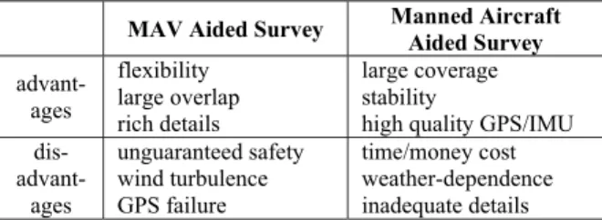
Table 1 compares MAV aided survey with manned aircraft aided survey. It is worth noting that these two image acquisition methods have complimentary characteristics. In view of this, it makes sense to fuse imagery taken from MAVs and manned aircrafts to obtain a better overall description of the scene. In principle, imagery acquired by manned aircrafts in higher altitudes provides a wider overview of the area, which supports effective overall planning and coordination; while imagery from MAV provides more details of the area of interest, which contributes to timely awareness and evaluation of emergencies. In addition, a fusion of both image types can provide a more complete view of the disaster area with detailed views on certain places as they are taken from different viewing directions and heights. Moreover, a parallel acquisition of aerial images from MAVs and aircrafts with minimal time-offset allows an efficient fusion of both image datasets for real-time situation awareness applications.
MAV Aided Survey Manned Aircraft Aided Survey
advant- ages
flexibility large overlap rich details
large coverage stability
high quality GPS/IMU
dis- advant-ages
unguaranteed safety wind turbulence GPS failure
time/money cost weather-dependence inadequate details
Table 1. Comparisons between MAV and manned aircraft aided survey.
Thus, a method for multi-view and multi-scale aerial imagery fusion is presented in this paper. The method can be divided into two procedures: first, the automatic absolute orientation of high-resolution MAV images using airborne image datasets with lower resolution as a reference; second, fusion of MAV and reference DEMs for subsequent classification. The paper analyses the problems, describes the methodology, the results The International Archives of the Photogrammetry, Remote Sensing and Spatial Information Sciences, Volume XL-1/W4, 2015
with experimental data and presents a concept for a subsequent 3D classification method.
2. MATERIAL AND METHODS
The fundamental step of image fusion is to establish a common reference frame for multi-scale imagery (Schenk et al., 2014). Deploying ground control points is neither economical nor realistic in the face of urgent events; on the other hand, it is easy to acquire aerial imagery with known orientations from previous surveying task. Considering the fact that MAVs are usually equipped with low-accuracy GPS/IMU system while manned aircrafts are equipped with high-end GPS/IMU and stable calibrated cameras, it makes sense to align the MAV imagery to the georeferenced image dataset taken from the manned aircraft. This is solved by image matching between MAV imagery and georeferenced aerial imagery, and then the problem becomes an orientation issue. The main workflow is illustrated in figure 1 and the processing details are elaborated below.
Figure 1. Flowchart of implemented fusion method.
2.1 SIFT matching
The implemented method for MAV image orientation is based on the tie information between reference imagery and MAV imagery. Here we use SIFT algorithm (Lowe, 2004) for feature detection and matching. Normally, the image is convolved with Gaussian filters at different scales and generates successive Gaussian-blurred images. In our case, a priori knowledge of the scale difference between MAV imagery and reference imagery is acquirable, so we can down sample the MAV imagery to an approximate scale of the reference imagery. After matching down sampled MAV imagery with original reference imagery, an initial fundamental matrix can be accordingly calculated which provides an estimation of the correspondence for subsequent matching.
2.2 Five point-RANSAC
After image matching, a number of matching pairs are detected. However, feature based image matching algorithms, such as SIFT, are normally operating using local pixel information and do not take all geometric constraints into consideration, thus leading to wrong matching pairs in the image matching result. In order to filter out these pairs, the five point-RANSAC algorithm (Nistér, 2004) is applied to remove outliers of the matching pairs among MAV images. Two corresponding image points and located on different images are related by a fundamental matrix F
:
0
(1)
Where,
det (F) = 0 (2)
The camera on the MAV is self-calibrated during relative orientation and results in an initial estimation of intrinsic parameters, which compose the intrinsic matrix K. The fundamental matrix is then reduced to an essential matrix, denoted by E, and the above relationship becomes (Hartley, 2004):
(3)
An essential matrix E has only five DOFs (Nistér, 2004). Consequently, to be a valid essential matrix E, it must further satisfy two more constraints, which are characterized by the following result:
2 0 (4)
Then we get nine equations in the elements of E, where only two equations are independent. Given five corresponding points, we can construct five epipolar equations of (1), the singularity condition equation of (2), and nine equations of (4). Then the essential matrix can be estimated. Given a number of random matching pairs which contain five point-tracks, we can apply the five-point algorithm to each sample and get a number of hypotheses. The best hypothesis is selected by a robust measure over all the point-tracks and then filtered by iterative refinement (Triggs et al., 2000).
2.3 GPS-based Filtering
The preceding section describes how to filter out wrong matching pairs based on the strict geometric constraint between two images, yet there is still a requirement on the number of correct matching pairs. In practice, due to the significant differences of scale, viewing direction and illumination between MAV and manned aircraft imagery, the mismatching probability of feature-based image matching algorithms are expected to be high. A severe situation is that matching between MAV imagery and reference imagery often generates too few matching pairs to perform RANSAC. Under the circumstances, on board GPS information, despite its inaccuracy, can provide a rough estimation of the position and help filter out wrong matching pairs
The relationship between image coordinate and ground coordinate can be expressed by the collinear condition equation: The International Archives of the Photogrammetry, Remote Sensing and Spatial Information Sciences, Volume XL-1/W4, 2015
(5)
where f = focal length x, y = image coordinates
, = coordinates of the principal point , , = coordinates of projection center X, Y, Z = object coordinates
With available GPS information of the MAV dataset, the MAV block generated from relative orientation can be transformed into absolute frame; IO/EO parameters of each image can therefore be obtained. Consider a common tie point T, which is detected on at least two MAV images {M1, M2 …} and at least
two reference images {R1, R2 …}, we can calculate the rough
3D coordinate ( , , ) of T with the orientation of the MAV image set {M1, M2 …} using equation (5) in combination
with a least squares adjustment. At the same time, we can also perform forward intersection on the reference image set {R1, R2
…} and get the coordinate of the same point T, denoted by ( , , ). The distance between the two estimated 3D coordinates is calculated:
(6)
In principle, if the current checking pair is correctly matched, then the 3D coordinates intersected by MAV image set and by reference image set should be quite close to each other. According to the positioning error of on-board GPS/INS system, a threshold Q is defined to judge the approximation of the two coordinates: if D > Q, this matching pair is judged to be a mismatched pair; otherwise, this matching pair is judged correct. It is assumed that the orientation of the reference dataset has better accuracy than the GPS position of the MAV dataset, so the coordinate ( , , ) generated from reference dataset is adopted as the valid 3D coordinate of tie point T.
2.4 Orientation and fusion
After filtering, we get a number of features with known image coordinates and object coordinates, which can therefore be used as ground control point (GCP) for MAV images orientation. If there are abundant GCPs, a few well distributed GCPs are chosen according to their coordinates. The final GCPs are introduced in the bundle adjustment to get the MAV block fully georeferenced. Since the GCPs are derived from the georeferenced dataset, MAV images are actually aligned into the same frame as the reference dataset. In this sense, a common reference frame is established. After orientation, the semi global matching (SGM) method (Hirschmuller, 2008, Angelo et al., 2011) is employed to find the stereo correspondence of the orientated MAV images. 3D regular point clouds and digital surface models (DSMs) of MAV images are generated afterwards. In the following steps, the newly generated DSM from MAV images and the DSM generated from geo-referenced aerial images are fused under the established common reference frame.
3. EXPERIMENTAL RESULTS
In this section experiments are carried out to test the proposed method. Experimental results are analysed and the performance is evaluated.
3.1 Test flights
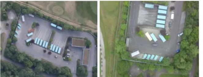
The test site (about 150 150 m2) is located in the town of Germering in south Germany, containing sub-urban structures, fields and motorways. The reference dataset was acquired on 16th June 2014 by the 4K sensor system with an accuracy about 0.05m (Kurz et al., 2014); the flight height is nearly 700m with an image GSD of 10cm. An Asctec Falcon-8 platform was used for MAV dataset acquisition with a size of 770 x 820 x 125 mm and a maximum payload of 0.8 kg. The camera mounted on-board was a GoPro HERO 3+ Black Edition whose focal length was fixed at 7.5mm. The MAV images are captured slightly shifted on 11th July 2014 at a flight height of 100m with an
image GSD of 2cm. In view that the MAV platform is mounted with a low-accuracy GPS/IMU system while the 4K system is equipped with high-end GPS/IMU and stable calibrated cameras, the 4K image dataset is assumed to have a higher absolute accuracy than the MAV image dataset. 17 MAV images of a recycling depot were chosen for the experiment, while 6 4k images containing the same area were chosen as the reference images. Figure 2 shows a 4K image and a MAV image, where significant differences in scale and view can be observed.
Figure 2. Examples of 4K image (left) and MAV image (right) used in the experiment.
3.2 MAV images orientation
Image matching was performed with SIFT++ (Vedaldi et al., 2010), an open source SIFT implementation developed by Andrea Vedaldi. The root mean square error of relative orientation is 1.158 pixels. Image orientation was performed with APERO (Deseilligny et al., 2011), an open source software developed by IGN. Even though GPS/INS information of all the 17 MAV images is available, we only utilized 9 GPS positions as a simulation for GPS loss. With a threshold Q of 10m, six matching pairs with known image coordinates and 3D coordinates were filtered and then used as GCPs to geo-reference the MAV block. Table 2 lists the residuals in X, Y, and Z and the re-projection error of each GCP. The average error is calculated with the absolute value of each individual error.
GCP Error in X (m)
Error in Y (m)
Error in Z (m)
Re-projection error (pixel)
1 0.001 -0.099 0.476 0.486
2 0.072 0.119 -0.196 0.240
3 0.016 0.149 -0.224 0.269
4 0.084 -0.158 0.411 0.448
5 -0.023 0.045 -0.287 0.291
6 -0.150 -0.056 -0.180 0.241
RMSE 0.077 0.113 0.316 0.344
Table 2. Residuals and re-projection errors at GCPs.
To compare the accuracy of the proposed method with georeferencing by means of GPS/INS orientations, the relative MAV block, which was generated from relative orientation in previous steps, was also georeferenced with on-board GPS position through bundle adjustment. Since our UAV platform has been calibrated beforehand, lever arm and misalignment angle were both taken into consideration and adjusted during bundle adjustment.
The accuracy of orientation was evaluated by residuals at selected check points, which were marked manually on georeferenced 4K images. The 3D coordinates of check points was calculated by forward intersection. Afterwards we marked the same check points on MAV images and calculated their coordinates using the interior and exterior orientations resulted from the proposed method and by means of GPS/INS orientations respectively. Residuals at checkpoints using these two methods are compared in Table 3. It can be seen that the proposed method achieved significantly higher accuracy at check points than GPS based direct geo-referencing. It should be pointed out that there is a significant difference of ground sampling distance (GSD) between the MAV imagery and reference imagery, which are 2cm and 10cm respectively. Such difference also contributes to the localization error of manually marking check points on images.
CP Proposed method GPS georeferncing X (m) Y (m) Z (m) X (m) Y (m) Z (m) 1 -0.075 -0.166 0.663 0.340 -1.995 2.056 2 -0.059 -0.321 0.908 0.492 -2.206 2.182 3 -0.061 -0.263 0.926 0.284 -2.184 2.621 4 -0.164 0.014 -0.087 0.005 -2.158 1.550 5 -0.217 -0.336 -0.052 0.450 -2.346 2.123 6 0.037 -0.256 0.745 0.313 -2.031 2.261 7 -0.326 -0.172 -0.184 0.070 -2.383 2.015 RMSE 0.167 0.242 0.623 0.326 2.190 2.136
Table 3. Comparison of check points residuals between proposed method and GPS based georeferncing.
3.3 Point cloud fusion
Then dense matching of MAV imagery is performed using the open-source MicMac software (Pierrot-Deseilligny et al., 2006). Figure 3 illustrates a comparison between the orthophotos generated from MAV image dataset and 4K image dataset. It can be seen that the orthophoto generated from MAV dataset has higher resolution and offers richer details than that from 4K dataset.
Figure 3. Comparison between 4K orthophoto (left) and MAV orthophoto (right) of the same area
The 3D point clouds of MAV dataset and 4K dataset were generated from depth maps respectively; then their DSMs were accordingly generated. Figure 4 compares the shaded DSMs generated from MAV image dataset and 4K image dataset respectively. The DSM of MAV dataset has a resolution of 0.02m while the resolution of 4K DSM is 0.2m. Such advantage in resolution contributes to the better visual effect of MAV DSM, as is shown in figure 4.
Figure 4. Comparison between 4K DSM (left) and MAV DSM (right) of the same area
With the proposed method, the 3D point cloud of the MAV image dataset has been aligned to the same reference frame as that of the 4K image dataset. Then we mixed the two 3D point clouds together and generated a fused point cloud, which has a larger density in the MAV surveyed area. Afterwards, the fused 3D point cloud was interpolated using the k-d tree structure (Bentley et al., 1975). Figure 5 illustrates the DSM generated from the fused 3D point cloud. The middle area was reconstructed with a combination of 4K images and MAV images while the outer area was generated from 4K images only. In this sense, the fused DSM not only retained the original information of the 4K images, but also achieved richer information in the MAV covered area.
Figure 5. DSM generated from fused 3D point cloud
4. CONCLUSION AND OUTLOOK
In this paper, a method for multi-view and multi-scale aerial imagery and DSM fusion has been presented. The implemented method enables the direct geo-referencing of MAV image datasets by registering to a reference image dataset. The results are quite encouraging as it not only achieves good accuracy exempt from deploying ground control points, but also reduces the dependence on GPS/IMU information. Furthermore, this method also takes fully advantage of previously georeferenced images acquired by manned aircraft, and once the current MAV dataset is georeferenced, it can be used in return as reference dataset for further survey tasks, which can be considered as an economical and promising way for geo-information updating.
The experiment was carried out offline, however, the method also has the potential to realize effective situation awareness in real-time. First, this method can achieve fully automatic processing without manual interaction. Besides, all possible image pairs were taken into consideration for feature matching during the experiment, which was quite computationally expensive. But once GPS/IMU information is available for MAV data, even partly, it can be employed as a priori knowledge to estimate overlapping images and thus significantly reduce the computation time. Additionally, the available GPS/IMU data can also be introduced as the initial value in the bundle adjustment and speed up the convergence.
On the other hand, there are also some aspects that need improving. For instance, only six points remained after filtering, which is inadequate to ensure robustness in further application. To deal with the problem, we consider combining other registration methods like cross correlation or pattern matching. Since correlation method does not require a search over image scale, it is generally more efficient than SIFT (Conte, 2009) and may help achieve more robust results. Our interest for further work also lies in the MAV point cloud based classification. As the source images are captured at different flight altitudes, the fusion of MAV point cloud and reference point cloud can present the scene from different views and provide complementary information. Furthermore, the MAV point cloud also contains detailed information, which is advantageous for classification. Existing point cloud classification methods, however, are generally based on geometric 3D-primitives such as planes, cylinders, spheres (Lafarge and Mallet, 2012). In our future work, we pursue to fully utilize the 3D position and RGB information of the geo-referenced and co-registered MAV point cloud for classification. With an integration of registered 3D position, RGB information as well as 3D-primitives, a higher classification accuracy would therefore be expected.
ACKNOWLEDGEMENTS
The authors would like to thank Martin Israel for the acquisition of the MAV images. Acknowledgements also go to Pablo d' Angelo and Peter Schwind for their support to the work.
REFERENCES
Bentley, J. L., 1975. Multidimensional binary search trees used for associative searching. Communications of the ACM, 18(9), 509-517.
Triggs, B., McLauchlan, P. F., Hartley, R. I., and Fitzgibbon, A. W., 2000. Bundle adjustment—a modern synthesis. In Vision algorithms: theory and practice. Springer Berlin Heidelberg, pp. 298-372.
Cesetti, A., Frontoni, E., Mancini, A., Ascani, A., Zingaretti, P. and Longhi, S., 2011. A visual global positioning system for unmanned aerial vehicles used in photogrammetric applications. Journal of Intelligent & Robotic Systems, 61(1-4), pp. 157-168.
Conte, G. and Doherty, P., 2009. Vision-based unmanned aerial vehicle navigation using geo-referenced information. EURASIP Journal on Advances in Signal Processing, pp. 1-8.
D’Angelo, P. and Reinartz, P., 2011. Semiglobal matching results on the ISPRS stereo matching benchmark. ISPRS-International Archives of the Photogrammetry, Remote Sensing and Spatial Information Sciences, pp. 79-84
Deseilligny, M. P. and Clery, I., 2011. Apero, an open source bundle adjustment software for automatic calibration and orientation of set of images. ISPRS-International Archives of the Photogrammetry, Remote Sensing and Spatial Information Sciences, 38(5/W16).
Eling, C., Klingbeil, L., Wieland, M. and Kuhlmann, H., 2014. Direct georeferencing of micro aerial vehicles–system design, system calibration and first evaluation tests. Photogrammetrie-Fernerkundung-Geoinformation, pp. 227-237.
Grenzdörffer, G. J., Engel, A. and Teichert, B., 2008. The photogrammetric potential of low-cost UAVs in forestry and agriculture. The International Archives of the Photogrammetry, Remote Sensing and Spatial Information Sciences, 31(B3), pp. 1207-1214.
Hartley, R. and Zisserman, A., 2003. Multiple view geometry in computer vision. Cambridge university press, pp. 241-259.
Hirschmuller, H., 2008. Stereo processing by semiglobal matching and mutual information. Pattern Analysis and Machine Intelligence, IEEE Transactions on, 30(2), pp. 328-341.
Kurz, F., Rosenbaum, D., Meynberg, O., Mattyus, G. and Reinartz, P., 2014. Performance of a real-time sensor and processing system on a helicopter. ISPRS-International Archives of the Photogrammetry, Remote Sensing and Spatial Information Sciences, Vol. XL-1, pp. 189-193.
Lafarge, F. and Mallet, C., 2012. Creating large-scale city models from 3D-point clouds: a robust approach with hybrid representation. International journal of computer vision, 99(1), pp. 69-85.
Lowe, D. G., 2004. Distinctive image features from scale-invariant keypoints. International Journal of Computer Vision, 60(2), pp. 91-110.
Nexa, F., Gerkeb, M., Remondinoa, F., Przybillac, H. J., Bäumkerc, M. and Zurhorstd, A., 2015. ISPRS benchmark for multi-platform photogrammetry ISPRS. ISPRS-Annals of Photogrammetry, Remote Sensing and Spatial Information Sciences, 1, pp. 135-142
Nistér, D., 2004. An efficient solution to the five-point relative pose problem. Pattern Analysis and Machine Intelligence, IEEE The International Archives of the Photogrammetry, Remote Sensing and Spatial Information Sciences, Volume XL-1/W4, 2015
Pierrot-Deseilligny M. and Paparoditis N., 2006. A multiresolution and optimization-based image matching approach: An application to surface reconstruction from SPOT5-HRS stereo imagery. In: Topographic Mapping From Space (With Special Emphasis on Small Satellites), ISPRS, Ankara, Turkey.
Schenk, T., Csatho, B., van der Veen, C. and McCormick, D., 2014. Fusion of multi-sensor surface elevation data for improved characterization of rapidly changing outlet glaciers in Greenland. Remote Sensing of Environment, 149, pp. 239-251.
Vedaldi, A. and Fulkerson, B., 2010. VLFeat: An open and portable library of computer vision algorithms. In Proceedings of the international conference on Multimedia, pp. 1469-1472.