DESIGN AND DEVELOPMENT OF A LOW
–
COST AERIAL MOBILE MAPPING
SYSTEM FOR MULTI-PURPOSE APPLICATIONS
C. Acevedo Pardo a, *, Mercedes Farjas Abadía b, Harald Sternberg a
a
HafenCity Universität Hamburg, 20457 Hamburg, Germany - (carlos.acevedo, harald.sternberg)@hcu-hamburg.de
b Universidad Politécnica de Madrid, ETSI Geodesia, Topografía y Cartografía, Madrid, Spain – [email protected]
Commission VI, WG VI/4
KEY WORDS: UAV, Mobile Mapping, Laser scanning, IMU, low-cost
ABSTRACT:
The research project with the working title "Design and development of a low-cost modular Aerial Mobile Mapping System" was formed during the last year as the result from numerous discussions and considerations with colleagues from the HafenCity University Hamburg, Department Geomatics. The aim of the project is to design a sensor platform which can be embedded preferentially on an UAV, but also can be integrated on any adaptable vehicle. The system should perform a direct scanning of surfaces with a laser scanner and supported through sensors for determining the position and attitude of the platform. The modular design allows his extension with other sensors such as multispectral cameras, digital cameras or multiple cameras systems.
.
* Corresponding author
1. INTRODUCTION
The last twenty five years have shown an increasing demand on 3D models for a large number of applications: like 3D city models; 3D models of the earth's surface for planning tasks; in the visualization of planning alternatives; in the sustainable urban development; etc. (see group SIG 3D, www.sig3d.org). Today 3D models are created (generated) through methods such as LIDAR, photogrammetry, terrestrial laser scanning or Mobile Mapping. In recent years the close-range photogrammetry arises with the use of UAV's (Unmanned Aerial Vehicles). We find this technology in a large number of applications, such as in "Disaster Research and Management" (Adams & Friedland, 2011); in "Rapid Aerial Monitoring for Emergency Responses" (Choi & Lee, 2011); in "Remote Sensing and Mapping" (Everaerts, 2008 and Eisenbeiss, 2011); in "3D Mapping" ( Jutzi, Weinmann & Meidow, 2013); in "Mobile 3D Mapping for Surveying Earthwork" (Siebert & Teizer, 2013); in "Landslide Surveying" (Carvajal, Agüera & Pérez, 2011); in "Applications for the Coal Industry" (Riley & Crowe, 2006); in archaeology (Seitz & Altenbach, 2011); in "Three-Dimensional Building Reconstruction" (Wefelscheid, Hänsch, & Hellwich, 2011); in "Real-Time Monitoring" (Witayangkurn, Nagai, Honda, Dailey & Shibasaki, 2011) and many more.
.
2. MOTIVATION
After a four years of testing an Octokopter from MikroKopter, Germany (see fig. 1 and 2), and the fact that a new acquisition should only be realized as part of a comprehensive concept, the idea of designing a new measuring system was born. After extensive research of the existing literature of recent years, it can be observed that almost the entire development in the UAV applications utilized a digital camera as the main sensor. The exceptions are two publications (Wallace, Lucieer & Watson,
2012 and Kuhnert & Kuhnert, 2013) which utilized a laser scanner as the main sensor. This acknowledgment plays an important role in the development of the new system.
Figure 1. Oktokoper take-off subsequent to the flight plan transfer
Figure 2. Images from a flight (HERICT-Project; Rhodes, Greece)
3. GENERAL DESIGN
The general concept for the developed system follows the proposed design and analysis from El Sheimy (1996).
3.1 System design
- Data recording and sensor selection
For the data acquisition it is necessary to select sensors for the measurement and the position determination during the flight in a corresponding range and accuracy. These components are: Laser scanner for data acquisition; an inertial measurement unit (IMU) for detecting the pitch, roll and heading; and a GNSS receiver to determine the system position and trajectory.
- Sensor Synchronization
The synchronization of all components (laser scanner, IMU, GNSS receiver) is necessary in order to calculate the final data. A control unit starts the measurement and stores the collected data for post-processing.
- System Calibration
The system must be calibrated to evaluate the sensors interior orientation.
- Kinematic model
The kinematic model involves the estimation, modeling and interpretation of the system trajectory by means of measurements in a reference coordinates system.
- Data geo-referencing
After the calibration is known and the kinematic model is determined, the measured data can be geo-referenced.
- Integration and fusion of data
If several sensors are used, the geo-referenced data must be integrated and fused together.
- Quality Control
The accuracy and reliability of data needs to be verified and validated through reference measurements on a test field.
.
Figure 3. Measurement process with base station and remote control unit
3.2 Flight platform
The system should be modular and independent. The flight and sensor platforms can work independently without using any performance from the other. The flight platform carries the sensor platform and follows the planned flight path. This concept allows the mounting of the sensor platform in different aerial or ground vehicles and could even be used manually.
Figure 4. Standard design of a flight platform
Manufacturer copterproject Hamburg Type CineStar 6HL Hexakopter Navigation MikroKopter flight control Position MikroKopter GPS V3 Engines T-Motor MN 4012-11 Batteries 2 x LiPo 4500 mAh
Table 1: Hexakopter technical specifications
The Hexacopter CineStar 6HL from copterproject, Hamburg and a gimbal (FreeFly) has been selected as the flight platform (for technical specifications see Table 1 and also fig. 4 and 5).
Figure 5. Hexakopter CineStar 6 HL (© copterproject Hamburg)
3.3 Sensor platform design
The sensor platform comprises the control unit, the GNSS receiver and corresponding antenna, an inertial measurement unit, and a laser scanner (see fig. 6). All components are mounted on the gimbal underneath the UAV. The flight platform and the sensor platform are held in place by a quick lock (see fig. 6 and fig. 7).
Figure 6. Sensor platform design
Figure 7. General concept of the flight and sensor platform
The position and trajectory of the sensor platform is determined by a GNSS receiver with the corresponding antenna. To avoid multipath and interferences, we placed a second GNSS antenna eccentrically on a carbon bar (each in the end of the bar) which is controlled by a dual GNSS receiver with the corresponding input for two antennas. This configuration is supported on the ground by a GNSS base station. An inertial measurement unit is firmly attached to the sensor platform. The advantage of this configuration is that the trajectory can better be evaluated. The measured base length is compared with the calibrated distance between the GNSS antennas to sort out possible outliers (see fig. 8).
Figure 8. Side view with the measuring system
The gimbal compensates the movements of the flight platform and keeps the sensor platform in an approximate horizontal position during the data collecting and the IMU detects every movement in a sufficient accuracy (see Fig. 9).
Fig. 9: The measuring system with the gimbal underneath the UAV
4. STATUS QUO AND DEVELOPMENT
The first investigations and the practical implementation of the measurement system has recently been performed in a master thesis at the HafenCity University. The concept was first implemented with the existing resources of the Department of Geomatics.
4.1 Components
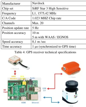
The laser scanner Sick LMS 151, a Xsens inertial measurement unit and a simple GPS receiver with PPS-output have been first tested. The Raspberry Pi Model B has been selected as controller, (see fig. 10 and fig. 11; tables 2, 3, 4 and 5). The technical specifications of the components are:
Fig. 10: SICK Scanner LMS 151, IMU - Xsens MTI-28A33G15, GPS receiver Navilock
Manufacturer/Type SICK LMS 151
Range 50 m
Scan angle max. 270 ° Angle resolution 0,5 ° / 0,25 ° Scan rate 50 Hz / 25 Hz Error Statistical: 12 mm
Systematic: ±30 mm
Temperature drift: max. 0,32 mm/°C Laser Laser class 1 (905 nm)
Beam divergence: 15 mrad (R15mm/m)
Beam diameter at outlet: 8 mm Weight 1,1 kg
Table 2: Laser scanner technical specifications
Manufacturer/Type Xsens MTI-28A33G15 Static accuracy Roll/Pitch: <0,5 °
Heading: <1 ° Dynamic accuracy 2 ° RMS Angle resolution 0,05 ° Time accuracy 10 ppm Dynamic range Pitch: ±90 °
Pitch/Heading: ±180 ° Max. update rate Onboard: 256 Hz
External: 512 Hz Dimension (Size) 58×58×22 mm Weight 50 g
Table 3: IMU technical specifications
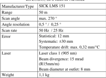
Manufacturer Navilock
Chip set SiRF Star 3 High Sensitive Frequency L1, 1575,42 MHz C/A Code 1.023 MHZ Chip rate Channels Max. 20
Position update rate 5 Hz Position accuracy 10 m
5 m with WAAS / EGNOS Speed accuracy 0,1 m /sec
Time accuracy 1 μs (synchronized to GPS time)
Table 4: GPS receiver technical specifications
Fig. 10: Rapsberry Pi, Model B and sensors
Manufacturer/Type Raspberry Pi, Model B Chip Broadcom BCM2835 CPU 700MHz ARM1176JZF-S GPU Broadcom VideoCore IV Main memory 512MB SDRAM Interface 2 x USB 2.0
10/100Mbit Ethernet GPIO
Power consumption 3,5 W
Dimension (Size) 9,3cm × 6,4cm × 2,0cm Operating system Linux
Weight 40 g
Table 5: Technical specifications Raspberry Pi
The Rapsberry Pi runs on a C++ program, which controls the GPS receiver (GPIO interface), the IMU (USB interface), the laser scanner (Ethernet interface) and also the data storage.
4.2 Data processing
The trajectory determination and the fusion with the laser scanner data was performed in MATLAB, by synchronizing the GPS time-stamp from the receiver (see fig. 11).
Fig. 11: Data processing
5. CONCLUSIONS AND OUTLOOK
The tests has shown that the conceiving system can be implemented as previously planned. The new system will be equipped with a new laser scanner (range up to 150m), an IMU with higher accuracy (roll/pitch/heading: 0,015°/0,015°/0,080°) and a GNSS (L1/L2) receiver. Currently we are working on the trajectory determination by a Kalman filter (Nøkland, 2011) and on the geo-referencing of the data. The future applications for the presented system are:
Topographical survey of the earth's surface (DTM), updating 3D city models, monitoring of landslides, 3D-recording of industrial facilities, evaluation of earthworks, documentation of archaeological excavations, etc. Further the following investigations are planned: system implementation with new sensors, validating the system on a test field, mapping the earth surface in real-time, obstacle detection during the flight, flight automation, data recording simultaneously with other measuring systems (ground or aerial), and the implementation of new measuring sensors.
REFERENCES
Adams, S. & Friedland, C., 2011. A Survey of Unmanned Aerial Vehicle (UAV) Usage for Imagery Collection in Disaster Research and Management. 9th International Workshop on Remote Sensing for Disaster Response. Stanford University, September 14-16, 2011.
Carvajal, F.; Agüera, F. & Pérez, M., 2011. Surveying a Landslide in a Road Embankment Using Unmanned Aerial Vehicle Photogrammetry. International Archives of the Photogrammetry, Remote Sensing and Spatial Information Sciences, Vol. XXXVIII-1/C22 UAV-g 2011, Conference on Unmanned Aerial Vehicle in Geomatics, Zurich, Switzerland.
Choi, K. & Lee, I., 2011. A UAV Based Close-Range Rapid Aerial Monitoring System for Emergency Responses. International Archives of the Photogrammetry, Remote Sensing and Spatial Information Sciences, Vol. XXXVIII-1/C22, UAV-g 2011, Conference on Unmanned Aerial Vehicle in Geomatics, Zurich, Switzerland, 2011.
Eisenbeiss, H. The Potential of Unmanned Aerial Vehicles for Mapping. Photogrammetrische Woche 2011, Dieter Fritsch (Ed.), Wichmann Verlag, Heidelberg, pp. 135-145.
El-Sheimy, N., 1996. The Development of VISAT - A Mobile Survey System for GIS Applications (Ph.D. thesis), UCGE Report No. 20101. Department of Geomatics Engineering, the University of Calgary, Canada.
Everaerts, J., 2008. The use of unmanned aerial vehicles (UAVs) for remote sensing and mapping. Proceedings of the XXI ISPRS Congress: 3-11 Jul 2008, Beijing, China. Proceedings Volume: IAPRS, Vol.XXXVII, ISSN 1682-1750.
Jutzi, B.; Weinmann, M. & Meidow, J., 2013. Improved UAV-borne 3D Mapping by fusing optical and laserscanner data. International Archives of the Photogrammetry, Remote Sensing and Spatial Information Sciences, Volume XL-1/W2, 2013, UAV-g2013, p. 223-228, 4 – 6 September 2013, Rostock, Germany.
Kuhnert, K.-D. & Kuhnert, L., 2013. Light-Weight Sensor Package for Precision 3D Measurement with Micro UAVs e.g. Power–Line Monitoring. International Archives of the Photogrammetry, Remote Sensing and Spatial Information Sciences, Volume XL-1/W2, 2013, UAV-g2013, 4 – 6 September 2013, Rostock, Germany.
Li, Z. & Li, Y., 2011. Photogrammetric Recording of Ancient Buildings by Using Unmanned Helicopters- Cases in China. International Archives of the Photogrammetry, Remote Sensing and Spatial Information Sciences, Vol. XXXVIII-1/C22 UAV-g 2011, Conference on Unmanned Aerial Vehicle in Geomatics, Zurich, Switzerland.
Manyoky, M.; Theiler, P.; Steudler, D. & Eisenbeiss, H., 2011. Unmanned Aerial Vehicle in Cadastral Applications. International Archives of the Photogrammetry, Remote Sensing and Spatial Information Sciences, Vol. XXXVIII-1/C22 UAV-g 2011, Conference on Unmanned Aerial Vehicle in Geomatics, Zurich, Switzerland.
Nøkland, H., 2011. Nonlinear Observer Design for GNSS and IMU Integration. Master Thesis, Department of Engineering Cybernetics, Faculty of Information Technology, Mathematics and Electrical Engineering, Norwegian University of Science and Technology.
Riley, P. & Crowe, P., 2006. Airborne and Terrestrial Laser Scanning – Applications for Illawarra Coal, in Aziz, N (ed), Coal 2006: Coal Operators' Conference, University of Wollongong & the Australasian Institute of Mining and Metallurgy, 2006, pp. 266-275.
Seitz Chr. & Altenbach, H., 2011. Project ARCHEYE – The Quadrocopter as the Archaeologis´s Eye. International Archives of the Photogrammetry, Remote Sensing and Spatial Information Sciences, Vol. XXXVIII-1/C22 UAV-g 2011, Conference on Unmanned Aerial Vehicle in Geomatics, Zurich, Switzerland.
Siebert, S. & Teizer, J., 2013. Mobile 3D Mapping for Surveying Earthwork Using an Unmanned Aerial Vehicle (UAV). Proceedings of the 30th ISARC 2013, Montréal, Canada.
Wallace, L.; Lucieer, A. & Watson, C., 2012. Assessing the Feasibility of UAV-Based LIDAR for High Resolution Forest Change Detection. International Archives of the Photogrammetry, Remote Sensing and Spatial Information
Sciences, Volume XXXIX-B7, 2012, XXII ISPRS Congress, 25 August – 01 September 2012, Melbourne, Australia.
Wefelscheid, C.; Hänsch, R. & Hellwich, O., 2011. Three-Dimensional Building Reconstruction Using Images Obtained by Unmanned Aerial Vehicles. International Archives of the Photogrammetry, Remote Sensing and Spatial Information Sciences, Vol. XXXVIII-1/C22 UAV-g 2011, Conference on Unmanned Aerial Vehicle in Geomatics, Zurich, Switzerland.
Witayangkurn, A.; Nagai, M.; Honda, K.; Dailey M. & Shibasaki, R., 2011. Real-Time Monitoring System using Unmanned Aerial Vehicle Integrated with Sensor Observation Service. International Archives of the Photogrammetry, Remote Sensing and Spatial Information Sciences, Vol. XXXVIII-1/C22 UAV-g 2011, Conference on Unmanned Aerial Vehicle in Geomatics, Zurich, Switzerland.
Revised July 2015