DOI: 10.13164/re.2016.0783 CIRCUITS
Utilization of Euler-Lagrange Equations
in Circuits with Memory Elements
Zdenek BIOLEK
1, Dalibor BIOLEK
1,2, Viera BIOLKOVA
11
Dept. of Microelectronics/Radioelectronics, Brno University of Technology, Technická 10, 616 00 Brno, Czech Republic
2
Dept. of EE, University of Defense, Kounicova 65, 662 10 Brno, Czech Republic
zdenek.biolek@gmail.com, dalibor.biolek@unob.cz, biolkova@feec.vutbr.cz
Manuscript received August 30, 2016
Abstract. It is well known that the equation of motion of a system can be set up using the Lagrangian and the pation function, which describe the conservative and dissi-pative parts of the system. However, this procedure, consisting in a systematic differentiation of the above state functions, cannot be used for circuits containing simulta-neously conventional nonlinear elements such as the resistor, capacitor, and inductor, and their nonlinear memory versions – the memristor, memcapacitor, and meminductor. The paper provides a general solution to this problem and demonstrates it on the example of modeling Josephson’s junction.
Keywords
Resistor, capacitor, inductor, memristor, memcapaci-tor, meminducmemcapaci-tor, content, energy, action, Lagrangian
1.
Introduction
The memristor (memory resistor, MR), memcapacitor (memory capacitor, MC), and meminductor (memory inductor, ML) are memory versions of the resistor, capaci-tor, and inductor. Their ability to store the information in a nonvolatile way and, concurrently, to perform logic oper-ations predetermine them for revolutionary applicoper-ations in computer engineering. All three memory elements are linked to L. Chua: In 1976, he introduced the memristor as a hypothetical element into the circuit theory in [1]. In 2008, he got satisfaction via the invention of a nanodevice with the memristive behavior in Hewlett Packard labs [2]. The concept of the so-called Chua periodical table was published in 1980 [3]. It shows that the classical RCL ele-ments and also their memory versions are mere special cases of the so-called higher-order elements (HOEs). The position of each HOE in the table, which resembles the Mendeleyev periodical table of chemical elements, corre-sponds with the unique features of this HOE. Just as all complex structures of the physical world are compounded from atoms of the elements from Mendeleyev table, an arbitrary electrical circuit can be made up exclusively
from HOEs from Chua’s table. As shown in [4], [5], this fact opens the way for a new modeling approach, which can be useful in the analysis of complex phenomena in biological systems [6] and in the world of nanotechnology [7]. However, a general procedure of modeling complex mem-systems via the elements from Chua’s table has not been hitherto published. The current research focuses more likely on the extension of the original definition of the memristor in order to describe the complex properties of existing memristive devices. One illustrative example is represented by the excellent paper [8].
A popular conceptual symmetries of the R-L-C-MR
elements as a small square section of Chua’s table, pub-lished in [2], is frequently used to explain the memristor as the “fourth fundamental electrical element”. Its extension
Fig. 1. Storeyed structure of a subset of fundamental elements [7]. The notation is specified in Sec. 2.
v
dv=R di i
q
t
t
d i q
0
) (
t
t
d v
0
) (
t
t
d q
0
) (
t
t
d
0
) (
dt d
dt d v
dt d q
dt dq i dq
for the MC and ML elements, called the storeyed structure [7], hereinafter abbreviated to StS, is shown in Fig. 1.
The StS shows that above the storey of classical
R-L-C elements there is a storey of their memory versions
MR-ML-MC. Each of the sextuplet of fundamental ele-ments in Fig. 1 introduces an unambiguous linkage, the so-called constitutive relation (CR), between the constitutive variables, which are time-domain integrals of the corre-sponding orders of terminal voltage v and flowing current
i. The element is regarded as nonlinear if its constitutive relation is also nonlinear.
Procedures of the analysis of circuits containing not only the classical R-L-C but also MR-ML-MC elements were published in [9], [10]. The papers [11], [12] are de-voted to the problem of setting up equations of motion for such circuits in the form of the Euler-Lagrange equations (hereinafter abbreviated to Lagrange equations), with the methods of loop currents or nodal analysis being made use of. It turns out that the extension of these methods to cir-cuits with memory elements is not trivial. Troubles may appear, for example, if nonlinear elements from both sto-reys of the StS exist within one loop or between two nodes. In such cases, the equation cannot be derived in a classical way, i.e. via a systematic differentiation of the state func-tions.
The present work deals with the problem given above. The procedure is as follows: Section 2 describes relation-ships between the constitutive relations of the elements and their state functions, the latter being the quantities content, energy, action, and time-domain integral of action (de-noted in the paper as the evolution) for the R-L-C- MR-ML-MC elements. Section 3 summarizes the results from [11] that concern the extension of the method of the Lagrange equations to circuits compounded exclusively from the memelements, and it presents this extension against the background of novel knowledge about the duality between classical and memory elements [13]. Section 4 illustrates problems with setting up the Lagrange equations of a cir-cuit that contains an arbitrary mix of nonlinear classical elements and nonlinear memory elements. It also provides a general solution to and a demonstration of a concrete application.
2.
Relationship between CR and State
Function
Let us denote the HOEs by the nonpositive integer indices and , which are used for their identification in Chua’s table. The CR of the (, ) element is an unambig-uous relation between the quantities v() and i(), where
dt vdt
v
1 ,
dt idt
i
1 (1)are the –th- and –th-order time-domain integrals of voltage and current. An annotated survey of the quantities represented by these integrals is shown in Tab. 1.
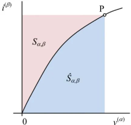
Figure 2 illustrates the connection between the CR of the (, ) element and its state functions
v di
S , , Sˆ ,
i dv . (2) When integrating from zero, the state functionscorre-spond to the areas according to Fig. 2, and the following equality holds:
, ˆ ,
S S v i . (3)
The pair of state functions in (3) contains one func-tion and one cofuncfunc-tion. These two complementary entities have been used since the nineteenth century [14]. The current form was introduced by Cherry [15] for the energy and Millar [16] for the content. The content was then ex-tended to memristive elements [17], [18]. A survey of the state functions and cofunctions (the latter designated by an asterisk) for the sextuplet of fundamental elements from Fig. 1 is given in Tab. 1.
The state function and cofunction provide additive properties, namely the sum of their values for individual subsystems forms the resulting value for the complete system. The value of the state function associated with the state of the system depends exclusively on this state and not on the way the system attained the state.
Fig. 2. Geometric meaning of state functions as areas belonging to the CR of the element. P denotes the current state of the element.
( , ) v(), i() S, Ŝ,
R ( 0, 0) v, i C C* content [W]
L (–1, 0) , i T* T energy [J]
C ( 0, –1) v, q V V* energy [J]
MR (–1, –1) , q A A* action [Js]
ML (–2, –1) , q X* X evolution [Js2]
MC (–1, –2) , Y Y* evolution [Js2]
Tab. 1. Constitutive variables and state functions of six fundamental elements. The symbols v, i, , and q
present voltage, current, flux, and charge, and are time-domain integrals of the flux and charge, T and V
are the kinetic and potential energy, X and Y are the kinetic and the potential evolution, * denotes the corresponding cofunction.
v() i()
Ŝ,
S,
0
Energies are well-known state functions. For example, the “potential” energy stored in the electrostatic field of the nonlinear capacitor with the CR of the type
v = vC (q) is
0 1
0, 1 C
V S
v di
v q dq. (4)It follows from the integral character of the state functions and cofunctions (2) that
v di dS
,
, dSˆ ,
i dv
. (5)
Formulae (5) can be read such that the instantaneous values of the constitutive variables are equal to the gradi-ents of the state functions or cofunctions at the operating point. The constitutive relation as a relation v() = v()^(i()) or i() = i()^(v()) can be also written in the form
,
v m i i , i n ,
v v
(6)
where
di dv di
S d i
m ,2
2
, ,
2 ,
, 2
ˆ
d S di n v
dv dv
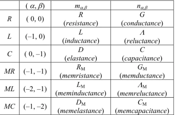
(7) are the differential (small-signal) parameters of the element representing nonlinearity, and m, = 1/n,. A concrete
form of these parameters for six fundamental elements is shown in Tab. 2.
( , ) m, n,
R ( 0, 0) R (resistance)
G
(conductance)
L (–1, 0) L (inductance)
(reluctance)
C ( 0, –1) D (elastance)
C
(capacitance)
MR (–1, –1) RM (memristance)
GM
(memductance)
ML (–2, –1) LM
(meminductance)
M
(memreluctance)
MC (–1, –2) DM (memelastance)
CM
(memcapacitance)
Tab. 2. A survey of differential parameters of six fundamental elements.
3.
Setting up Lagrange Equations
The behavior of a system containing only inductors, capacitors, and resistors (i.e. elements from the “ground floor” of the StS) is given by the Lagrange equations of motion. These equations can be obtained via a systematic differentiation of the state function of the circuit, namely the Lagrange and the dissipation function. The procedure is as follows: The Lagrange function L(·) or the cofunction
L*(·)
T VLq,q * , L*
,
V*T, (8)is derived from the reactance part of the circuit. The charges and fluxes in (8) are associated in the vector varia-bles. For details about the variables V, V*, T, and T* see Tab. 1. The Lagrange function or cofunction (8) has the physical measure of energy, i.e. its unit is Joule [J]. The function content C(·) or the cofunction cocontent C*(·) (see Tab. 1) is determined from the part of the circuit that in-cludes the dissipative elements. The procedure
d L L C
dt
vext
q q q
,
* * *
d L L C
dt
iext, (9)
generates the vector equations of motion, where vext and iext
are vectors of the voltage and current excitations. If the method of loop currents or nodal analysis is used, then (9) are equations of KVL for loops or equations of KCL for nodes. The first, second, and third left-side terms of (9) represent the sums of voltage or current contributions from the inductors, capacitors, and resistors in the loop or in the branches leading to the corresponding node.
The method will be illustrated on the well-known Chua circuit in Fig. 3. In the version (a), the circuit is com-pounded exclusively from the elements from the ground floor of the StS, namely from one linear inductor, two linear capacitors, one linear resistor, and the so-called Chua diode, which is an active nonlinear resistor with the constitutive relation [13]
CHUA
1 1
2
v v
ii v bv ab , (10)
with a and b being properly chosen real numbers.
The Lagrange cofunction (8) has the form
* 2 2 2
1 A 2 B A
1 1 1
,
2 2 2
L C C , (11)
where A and B are the time-domain integrals of voltages
of the nodes A and B against the ground, and = L–1 is the
Fig. 3. Chua’s circuit with (a) Chua’s diode as a nonlinear resistor, (b) Chua’s memristor.
L C1 C2 MRCHUA
R
RCHUA
A B
inverse inductance. The cocontent of Chua’s diode is the integral of the CR (10) with respect to the voltage
v = d/dt. The procedure (9) leads to the set of equations of motion
1 A B A CHUA B 0
C G i ,
2 B B A B 0
C G , (12) where G = R–1 is the conductance of the resistor R.
For circuits compounded only from memristors, mem-capacitors, and meminductors, i.e. elements occupying the first floor of the StS, Jeltsema suggests the following pro-cedure [11]: The Lagrange function LM(·) or cofunction LM*(·)
*M ,
L σ σ X Y , *
*M ,
L ρ ρ Y X , (13) is derived from the reactance part of the circuit. The time-domain integrals of charges and fluxes in (13) are associ-ated in the vectors of the circuit variables. For details about the variables X, X*, Y, and Y* see Tab. 1. The Lagrange function or cofunction (13) has the physical dimension of energy multiplied by the square of time, i.e. its unit is [Js2]. The function action A(·) or the cofunction A*(·) (see Tab. 1) is determined from the part of the circuit that in-cludes the dissipative elements. The procedure
M M
d L L A
dt
ext
σ σ σ ,
* * *
M M
d L L A
dt
ext
q
ρ ρ ρ , (14)
generates the vector equations of motion, where ext and
qext are the time-domain integrals of the voltage and current
excitations vext and iext. Equations (14) represent
Kirch-hoff’s flux law (KFLL) for loops and KirchKirch-hoff’s charge law (KCHL) for nodes [13], denoted in [11] as iKVL and iKCL. The first, second, and third left-side terms of (14) represent the sums of flux or charge contributions from the meminductors, memcapacitors, and memresistors in the loop or in the branches leading to the corresponding node.
The extension (14) of the Lagrange equations by Jeltsema is readily comprehensible from the point of view of the principle of duality [13]. According to this principle, the pairs R-MR, C-MC and L-ML are dual to each other if their constitutive variables are coupled by identical consti-tutive relations. Then the circuit variables and of the circuit containing only memelements (whose special cases are the classical memoryless linear elements) conform to the same equations of motion as the variables and q of the circuit in which the memelements were replaced by dual nonlinear elements. The formal conformity of the equations of motion (9) and (14) is an expression of the fact that the dynamics of the circuit with memoryless R, L,
C elements is identical to the dynamics of its dual circuit containing MR, MC, and ML elements.
The circuits in Figs 3(a) and 3(b) are dual to each other if the current and voltage of Chua’s diode are linked by the same constitutive relation i = iCHUA(v) as the charge
and flux of Chua’s memristor q = qCHUA(), i.e. iCHUA(·) ≡qCHUA(·). The linear elements C1, C2, R, and L
can be regarded as the memelements MC1, MC2, MR, and ML with linear constitutive relations. The Lagrange co-function (13) is a difference between the potential coevo-lution of the capacitors and the kinetic evocoevo-lution of the (mem)inductor, and it has the form
* 2 2 2
M 1 A 2 B A
1 1 1
2 2 2
L ρ ρ C C . (15)
A and B are the second-order time-domain integrals of
voltages of the nodes A and B against the ground. The coaction of Chua’s memristor is the integral of the consti-tutive relation qCHUA(·) with respect to the flux = d/dt.
The procedure (14) leads to the set of equations of motion
1 A B A CHUA B 0
C G q ,
2 B B A B 0
C G . (16) Equation (16) for and Equation (12) for are formally
identical. This is in conformity with the duality of circuits in Figs 3(a) and 3(b).
4.
Problem and Its Solution
Hitherto published methods of drawing up the La-grange equations via state functions are applicable only to circuits that are exclusively composed of elements of one kind: they must belong either to the ground (“classical”) or to the first (“memory”) floor of the StS. Drawing-up the equations of motion is governed by the well-known meth-odology (9) for the first case and by the extension by Jeltsema (14) for the second case. Linear resistors, capaci-tors, and inductors can be considered as memelements with linear constitutive relations. That is why the linear element from an arbitrary floor of the StS can be included in either the first or the second group as necessary.
It follows from the above that the procedure of selecting either the method (9) or (14) cannot be used for circuits that contain simultaneously nonlinear classical and
nonlinear memory elements. Nevertheless, the general solution is easy, as described below.
Consider that we know the (co)functions L(·), C(·) from (9) and LM(·), A(·) from (14), which describe the parts
M M
d d L L A
dt dt
σ σ σ
d L L C
dt
ext
v
σ σ σ . (17)
The first/second term represents the voltage contributions from the memelements/classical elements. The set of KCL equations for the nodal voltages is in the form
* * *
M M
d d L L A
dt dt
ρ ρ ρ
* * *
d L L C
dt
ρ ρ ρ iext. (18)
The first/second term represents the current contributions from the memelements/classical elements.
Let us apply the procedure (18) to the circuit in Fig. 4, consisting of all six nonlinear elements from the StS in Fig. 1. According to (8), the Lagrange cofunction L*(·) of the memoryless part of the circuit is
*
C L
0 0
,
L q v dv i d
. (19)The cocontent of the nonlinear resistor is given by the formula
*
R 0
C i v dv
. (20)
The functions with the indices L, C, and R in (19) and (20) are the constitutive relations of the respective elements. The Lagrange cofunction (13) LM*(·) of the memory part of
the circuit is in the form
*
M MC ML
0 0
,
L q dq q d
. (21)
The functions with the indices MC and ML are the consti-tutive relations of the memcapacitor and meminductor. The memristive coaction is
1
*
MR 0
A q d
. (22)
Fig. 4. Parallel C-MC-R-MR-L-ML circuit.
The function with the suffix MR is the constitutive relation of the memristor.
Applying the procedure (18) to the functions (19)– (22) yields the KCL equations of the circuit
M M
C G
2
M
M
dC
d
L
R
0C i i
, (23)
where C(·) is a voltage-dependent capacity, and iL(·) and iR(·) are generally nonlinear constitutive relations of the
inductor and resistor.
The model of Josephson’s junction is shown in Fig. 5 [13]. The C and R elements are linear, and the nonlinear constitutive relations of the inductor and memristor are as follows:
L 0sin
i I k , qMR
G0sin
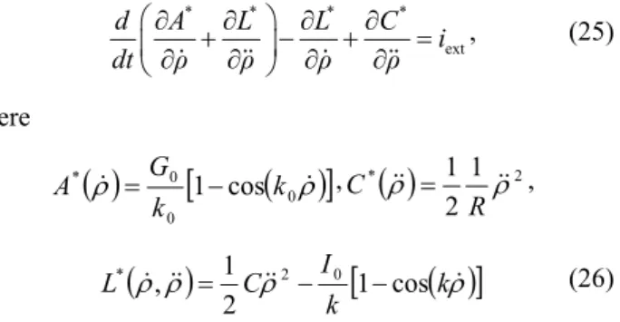
k0 , (24) where I0, k, G0, and k0 are constants.Since the circuit in Fig. 5 contains no memcapacitor and no meminductor, the Lagrange cofunction LM*(·)
according to (13) does not exist. The equation of motion (18) can be simplified to the form
* * * *
ext
d A L L C
i
dt ρ ρ ρ ρ
, (25)
where
0
0 0 *
cos
1 k
k G
A , *
1 22 1
R
C ,
k
kI C
L 1 cos
2 1
, 2 0
* (26)
are state functions as integrals of the constitutive relations (24) and linear constitutive relations of the resistor R and capacitor C. The procedure (25) leads to the equation of motion, which can, with respect to the equality = d/dt, be written as
Fig. 5. Model of Josephson’s junction as a parallel connection of linear capacitor, linear resistor, nonlinear inductor, and memristor.
L MR
C R
iext ML
MC MR
C R L
0 0 0 0 ext
1
cos sin
C G k k I k i
R
. (27)
Note that this is in agreement with the results published in [13].
5.
Conclusions
The well-known classical form of the Lagrange equa-tion (9), which starts from the knowledge of the state func-tions of reactive elements and the content of dissipative elements, cannot be applied to circuits containing memristors (MR), memcapacitors (MC), and meminductors (ML). This paper provides a generalization in the form of the procedure (17) or (18), which facilitates setting up the KVL- or KCL-type Lagrange equations of a circuit containing an arbitrary combination of classical R-L-C
elements and their memory versions MR-ML-MC. The equations can be set up based on the knowledge of the constitutive relations of the individual elements and the information about their interconnection.
It follows from the analysis of the procedures (9) and (14) that, if the circuit contains only elements from one floor of the storeyed structure in Fig. 1, the method of the loop or node analysis can lead to a set of nonlinear differ-ential equations of order not higher than 2. If the elements belong to both floors, the order of the resulting equation cannot be higher than 3.
The method deals with the way of drawing up the Lagrange equations of the circuit based on the knowledge of the potential functions of the circuit elements. It does not address the question of whether the variational princi-ple, which was originally associated with the idea of the Lagrangian of the system, is or is not fulfilled.
Acknowledgments
This paper originated as part of the activities of the COST Action IC1401 ”Memristors – Devices, Models, Circuits, Systems and Applications (MemoCIS)” and is financially supported by the Czech Ministry of Education under grant No LD15033. This work was also supported by the Czech Science Foundation under grant No. 14-19865S, Czech Republic. For research, the infrastructure of K217 UD Brno was used.
References
[1] CHUA, L. O. Memristor – The missing circuit element. IEEE Transactions on Circuit Theory, 1971, vol. CT-18, no. 5, p. 507 to 519. ISSN: 0018-9324. DOI: 10.1109/TCT.1971.1083337
[2] STRUKOV, D. B., SNIDER, G. S., STEWART, D. R., WILLIAMS, R. S. The missing memristor found. Nature, 2008, vol. 453, p. 80–83. ISSN: 0028-0836. DOI: 10.1038/nature06932
[3] CHUA, L. O. Device modeling via nonlinear circuit elements.
IEEE Transactions on Circuits and Systems, 1980, vol. 27, no. 11, p. 1014–1044. ISSN: 0098-4094. DOI: 10.1109/TCS.1980.1084742
[4] CHUA, L. O., SZETO, E. W. High-order non-linear circuit elements: Circuit-theoretic properties. International Journal of Circuit Theory and Applications, 1983, vol. 11, no. 2, p. 187–206. ISSN: 1097-007X. DOI: 10.1002/cta.4490110206
[5] CHUA, L. O. Nonlinear circuit foundations for nanodevices. I. The four-element torus. Proceedings of the IEEE, 2003, vol. 91, no. 11, p. 1830–1859. ISSN: 0018-9219. DOI: 10.1109/JPROC.2003.818319
[6] DI VENTRA, M., PERSHIN, Y. V. Biologically-inspired electronics with memory circuit elements. Advances in Neuromorphic Memristor Science and Applications, 2012, vol. 4 of the series Springer Series in Cognitive and Neural Systems, p. 15–36. ISBN: 978-94-007-4490-5. DOI: 10.1007/978-94-007-4491-2_3
[7] BIOLEK, D., BIOLEK, Z., BIOLKOVÁ, V. SPICE modeling of memristive, memcapacitative and meminductive systems. In
European Conference on Circuit Theory and Design, 2009, p. 249–252. CD-ROM ISBN: 978-1-4244-3896-9. DOI: 10.1109/ECCTD.2009.5274934
[8] CHUA, LO. Everything you wish to know about memristors but are afraid to ask. Radioengineering, 2015, vol. 24, no. 2, p. 319 to 368. ISSN: 1210-2512. DOI: 10.13164/re.2015.0319
[9] HAJJ, I. N. Extended nodal analysis. IEEE Transactions on Computer-Aided Design of Integrated Circuits and Systems, 2012, vol. 31, no. 1, p. 89–100. ISSN: 0278-0070. DOI: 10.1109/TCAD.2011.2167330
[10] RIAZA, R. Second order mem-circuits. International Journal of Circuit Theory and Applications, 2015, vol. 43, no. 11, p. 1719 to 1742. ISSN: 0098-9886. DOI: 10.1002/cta.2037
[11] JELTSEMA, D. Memory elements: A paradigm shift in Lagrangian modeling of electrical circuits. IFAC Proceedings Volumes, 2012, vol. 45, no. 2, p. 445–450. ISSN: 1474-6670. DOI: 10.3182/20120215-3-AT-3016.00078
[12] COHEN, G. Z., PERSHIN, Y. V., DI VENTRA, M. Lagrange formalism of memory circuit elements: classical and quantum formulations. Physical Review B, 2012, vol. 85, no. 16, p. 165428-165430. DOI: 10.1103/PhysRevB.85.165428
[13] ITOH, M., CHUA, L. O. Duality of memristor circuits. Interna-tional Journal of Bifurcation and Chaos, 2013, vol. 23, no. 1, p. 1 to 50. ISSN: 0218-1274. DOI: 10.1142/S0218127413300012
[14] FRANKSEN, O. I. The nature of data — From measurements to systems. BIT Numerical Mathematics, 1985, vol. 25, no. 1, p. 24 to 50. ISSN: 0006-3835. DOI: 10.1007/BF01934986
[15] CHERRY, E. C. Some general theorems for non-linear systems possessing reactance. Philosophical Magazine, 1951, series 7, vol. 42, no. 333, p. 1161–1177. ISSN: 0031-8086. DOI: 10.1080/14786445108561362
[16] MILLAR, E. C. Some general theorems for non-linear systems possessing reactance. Philosophical Magazine, 1951, series 7, vol. 42, no. 333, p. 1150–1160. ISSN: 0031-8086. DOI: 10.1080/14786445108561361
[17] BIOLEK, D., BIOLEK, Z., BIOLKOVÁ, V. Interpreting area of pinched memristor hysteresis loop. Electronics Letters, 2014, vol. 50, no. 2, p. 74–75. ISSN: 0013-5194. DOI: 10.1049/el.2013.3108
About the Authors ...
Zdeněk BIOLEK was born in Ostrava, Czech Republic, in 1959. He received the PhD degree in Electronics and Informatics from Brno University of Technology, Czech Republic, in 2001.
He is currently with the Department of Microelectronics, Brno University of Technology (BUT), Czech Republic. Until the year 1993 he worked as independent researcher in the semiconductor company TESLA Rožnov. He is the author of unique electronic instruments associated with IC production and testing. He is also the author of several papers from the area of the utilization of variational princi-ples in theoretical electrical engineering and stability test-ing of resistive circuits, and also from the field of memris-tors and mem-systems. Dr. Z. Biolek is also the co-author of two books about memristive systems and PSpice mod-eling and simulation of special electronic circuits including switched-capacitor filters, switched DC-DC converters, and memristors.
Dalibor BIOLEK received the MSc degree in Electrical Engineering from Brno University of Technology, Czech Republic, in 1983, and the PhD degree in Electronics from the Military Academy Brno, Czech Republic, in 1989, focusing on algorithms of the symbolic and numerical
computer analyses of electronic circuits with a view to the linear continuous-time and switched filters.
He is currently with the Department of EE, University of Defense Brno (UDB), and with the Department of Micro-electronics, Brno University of Technology (BUT), Czech Republic. His scientific activity is directed to the areas of general circuit theory, frequency filters, mem-systems, and computer simulation of electronic systems. He has pub-lished over 400 papers and authored several books on cir-cuit analysis and simulation. At present, he is professor at BUT and UDB in the field of Theoretical Electrical Engi-neering.
Prof. Biolek is a senior member of the CAS/COM Czech National Group of IEEE. He also serves as an Area Editor of the International Journal of Electronics and Communi-cations (AEU).
![Fig. 1. Storeyed structure of a subset of fundamental elements [7]. The notation is specified in Sec](https://thumb-eu.123doks.com/thumbv2/123dok_br/17052643.234318/1.892.473.823.677.1113/fig-storeyed-structure-subset-fundamental-elements-notation-specified.webp)