T
HE MASONRY BEHAVIOUR UNDER CONTACT
DETONATION
Marin LUPOAE Assoc. Prof., PhD, Military Technical Academy, Faculty of Mechatronics and Integrated Systems of Armament e-mail:[email protected]
Francois WINDECK Slt., French Military Academy of Saint Cyr e-mail: [email protected]
David BREAUD Major, French Military Academy of Saint Cyr e-mail:[email protected]
Cătălin BACIU Lecturer, PhD, Military Technical Academy, Faculty of Mechatronics and Integrated Systems of Armament e-mail:[email protected]
Abstract. Breaching in masonry wall as a process of quick intervention of special forces in emergency cases, may require the use of explosive charges. In order to maximize the explosive effects on the wall and to minimize the shock wave and fragments propulsion, such breaching systems usually use a water layer which cover the explosive charge. The thickness of the water layer has a significant influence both on the mitigation of unwanted effects and enhancing the demolition effect, but also increases the mass of the system which can have negative consequences on the maneuverability and rapidity of intervention, respectivly. In this respect, the paper under consideration addresses numerical and experimental research on masonry walls to determine the behavior of mortar and brick under contact detonation and to establish an optimal water layer thickness to balance the breaching system requirement related to the mass on the one hand and effects and offered protection on the other hand.
Key words: masonry, breaching, water layer, demolition, strain rate.
1. Introduction The use of breaching systems to get quick access through the walls of buildings, windows or doors becames a viable solution for saving people in crisis situation like earthquake, fire or terrorist attacks (Moldovan et al., 2015). Related to this
2005). Also, Moldovan and Enache (2015) established the optimum water layer thickness in order to mitigate the effects of shock waves on breaching works. In addition, Wang et al. (2009) studied the possibility of predicting the size and the propulsion distance for the masonry fragments resulting from an explosion.
There are three main types of explosive charges which can be used for breaching (Moldovanet al., 2015):
· cutting charges;
· pushing / fluid impulse charges;
· blast charges.
For breaching in masonry and light concrete walls cutting charges are used as flexible linear shaped charge. In order to improve the positive effects of these charges and reducing the fragment propulsion and overpressure, the explosive charge is included in a special breaching device as illustrated in Fig. 1.
Fig. 1. Explosive Wall Breaching systems and their effects on masonry wall
(Moldovanet al., 2015)
The water layer covering the explosive significantly reduces the speed of the fragments and attenuates the shock wave, decreasing thereby the risk of injury to the operator. The thickness of water layer should be large enough to ensure performance and safety requirements, but small enough to allow rapid intervention.
The first part of the paper is devoted to static and dynamic properties of masonry
and mortar and also the damage mechanism of these brittle materials under contact detonation. Subsequent sections are concerned with the experimental tests and numerical simulations to determine the mechanism of masonry destruction under contact detonation and to establish the optimal thickness of water layer in order to increase the explosive effects on breaching in masonry walls.
2. Masonry material Masonry is a really complex material composed of evenly aligned bricks joined with mortar mixture. Because of this composition masonry is a heterogeneous and anisotropic material. Bricks and mortar are both considered as brittle materials with good fireproof, acoustical, thermal isolation and resistance to flying debris properties (Linse et al., 2012). Bricks can be made of several materials like concrete, ceramic, or stone and they are one of the oldest building material. Usually under static and dynamic strain, bricks and mortar follow the same behavior patterns. Although the great variety of masonry exists, the ways used to analyse them and describe their properties are always the same. However, it can be distinguished two manners of loading masonry. First is the in-plane loading which puts at stake any other stress than those which are in the wall plane. Then opposite to the in-plane loading, out-plane one loading which creates stresses perpendicular to the wall plane. Thanks to its specific geometry, a masonry is obviously more weakened relatively to an out-plane loading usually such as blast or explosive detonation.
2.1. Dynamic properties of brick and mortar
of the material and the structure under the action of static and dynamic loads. Dynamic loads cause high stress and strain, leading to an increasing of the material strength due to the strain rate. The influence of the strain rate on the increase of the brittle material strength is fully described in numerous scientific papers: (Rosset al., 1989; Groteet al., 2001; Cotsovos and Pavlovic, 2008; Ridelet al., 2009; Zhou and Hao, 2008) for concrete and (Hao and Tarasov, 2008; Benedetti and Pelà, 2012; Pereiraet al., 2013) for mortar and masonry bricks. This increase can be quantified by the dynamic increase factor which is the fraction of dynamic strength relative to static strength (Fig. 2). At low strain rates, the masonry walls are governed by the strength of the masonry joints, but under high strain rates the masonry strength is given both by the mortar and the brick strength (Hao and Tarasov, 2008).
Fig. 2. Dynamic increase factor (DIF) for the tensile and compressive strength of mortar
and masonry bricks (after Sielicki, 2013)
It appears that the compressive strength of masonry strongly increases (around 2.5 times more than static case for strain rate of about 103 s-1) when the dynamic
increase factor for mortar is more than three for compressive strength.
2.2. Damage mechanisms of mortar and masonry under contact detonation
Damage mechanisms of mortar and masonry are not easily to be described.
Scientific literature gives a large view of every kind of theory regarding the damage effect of blast and detonation. However a normalized conception of damage has been developed, hence it is nowadays possible to categorize them under four levels (Wei and Stewart, 2011): · Superficial damages with thin line of
cracks in masonry and especially in mortar. Usually such damages let to consider the wall enough safe.
· Presence of cracks more and less large in mortar. Bricks might be cracked so that the wall is clearly weakened. · Important dislocation of the masonry.
Damage is usually important and the wall would have totally collapsed if the blast pressure is high enough. · Collapse of the masonry leading to its
total destruction.
Thereby borders between each categorize of damages seems sometimes not to be well defined. However one masonry response of a blast impulse is its deflection which could be considered as a criterion for collapsing wall under detonation. Indeed literature assumes that if the masonry deflection exceeds the wall thickness then it would collapse. Consequently to the dynamic behavior of mortar and masonry, the stresses developed by shock and detonation wave induce hardening and softening in materials. Such constitutive deformations usually lead to failures (Sielicki, 2013). The strengthening is due to the dislocation because plastic deformations are increased by the loss of coherency. Hardening effects appear to be dependent of the pressure and loading time.
Damage mechanisms are controlled by different common phenomena (Meyers, 1994) which could be subsequent in time: · The loss of coherency which appears
decreasing or increasing pressure in different places of the material. Indeed materials presents a special internal stress called coherency stress that is responsible for the coherence of the structure. This stress is usually an obstacle for the fragmentation of object under low shock. However, the overpressure is higher enough to overpass the coherency stress inducing the initiation of damage mechanisms.
· Shear bands are the region where plastic deformations are concentrated. These bands are the precursor of the cracks and failure in materials. In a way, shear bands are the path of the failure and the first really visible damage on materials. Cracks are the consequences of the break of the last step by a shock wave creating firstly micro cracks which increase under the reflected wave or vibration of the structure. Cracks propagate in the structure with specific velocity depending on material properties. In addition velocity of cracks propagation is limited by the Rayleigh wave velocity.
· Dislocation or fragmentation is last step of the damages process which appears when the material is divided in many cracks formed simultaneously. There are two modes of fragmentation: ductile or brittle. Brittle fragmentation is accompanied of sharp front for cracks where as ductile fragmentation leads to blunted failure. Dislocation generation seems to be only pressure dependent and controlled by the deviatoric stress. After dislocation a decay of stiffness is observed in masonry. The fragments produced by dislocation depend on the number of shock waves and the physical properties of the material. The density of fragments significantly
increases with pressure and time of loading. These different phenomena of damage mechanisms are all present in the general specific failure
which is induced in masonry
structures by the detonation of explosive charge.
It is possible to quantify damages (Wei and Stewart 2011) on structures using a theoretical approach. Damage is given by variable D which is always between 0 and 1 so that it could be seen as a percentage of the structure damage. First damage is usually given by a relation relative to the Young’s modulus:
(
D)
EE= 1
-0 , where D = 0 for intact
material and D = 1 for total destruction and failure. Furthermore damage, D, can be developed as following:
c c t
t D D
D=x × +x × , with xt +xc =1 and
0 ,
0 > > c
t D
D& & , where
t
x and xc are proportionality coefficients representing weight of each damage issued of tensile strain Dt, and compression strain Dc.
3. Experimental investigations For experimentations it was use a masonry brick wall, with French way of masonry arrangement, Fig. 3. The masonry wall was covered with one centimeter cement plaster, which was removed in order to
have the same conditions for
experimentations and simulations.
The explosive charge was made by detonationg cord with 100 g per meter and a diameter of 1 cm. The detonating cord was placed inside of a PVC semi tube along its simetry axis, Fig. 4.
Table 1. Test configurations and dimensions of the craters
Experiment no. Tube diameter (mm)
Water layer thickness (mm)
Crater width (mm) Crater depth (mm)
1 none none 20.2 32.4
2 28 9.0 15.1 45.0
3 36 13.0 13.4 47.1
4 47 18.5 14.7 53.3
5 71 30.5 13.3 52.3
6 71 30.5 18.0 48.9
7 47 18.5 27.5 50.1
The explosive devices placement
Fig. 3. The placement of explosive devices and the effects after detonations
It was used also a plastic explosive charge of 50 g. Although the mass of the explosive charge was clearly more important than the mass of detonating cord, there was not shown significant differences in breach dimensions, Table 1.
The last step of preparation was to fix in a proper way the explosive device on the wall before adding the detonator and join it to the electric line. Because a relatively homogeneous surface was obtained after the removal of the plater, there were used some wood supports for a proper fixation of the explosive device on the wall.
There were tested six explosive devices with detonating cord and one more with plastic explosive. All the configurations and the dimensions of the resulted craters are presented in Table 1.
Fig. 4. The explosive device preparation
4. Numerical simulations The masonry is a material that has different directional properties due to the mortar joints. The interface between brick and mortar acts as a plane of weakness. Masonry can be suitable represented for numerical analysis using a micro level model of individual components (brick and mortar) or a macro-level model, as a composite material. Depending on the level of accuracy it is possible to use the following strategies for modeling:
· Detailed modeling at the micro level when brick unit and joints of mortar are represented as continuum elements while the interface brick unit
- mortar is represented by
discontinuous elements;
· A complete macro-model must describe the orthotropic material behavior with different tensile and compressive strengths along the material axis and also different inelastic behavior for each axis (Lourenco and Rots, 1997). There are a lot of papers in the literature treating the problem of masonry modeling at micro or macro level: (Pietruszczak and Niu, 1992; Chaimoon and Attard, 2007; Shieh-Beygi and Pietruszczak, 2008; Marques and Lourenco, 2011; Ghiassi
et al., 2012; Baloevic et al., 2013). Because in the performed experiments the damaged area had small dimensions, it was used the micro-level modeling in order to simulate the influence of the water layer on the masonry wall breaching.
4.1. The influence of bricks arrangement
In order to reduce the computing time, which is directly linked to the number of mesh cells for modeling air and wall, it was used symmetry, both for x and y axis (Fig. 5). The masonry wall (bricks and mortar) was modeled using Lagrange solver while for air, water and explosive it was used Euler option. The bricks arrangement and orientation was not the same as in the experimental tests, so two types of modeling were considered in order to determine the influence of the bricks arrangement on numerical results. For the first type (Fig. 6a) it was used the implicit brick option of Autodyn to model a wall, taking into account mortar and bricks in the same box space, but without considering the bricks arrangement corresponding to experimentations. Second type (Fig. 6b), more difficult to implement, was created by using the same brick option of Autodyn, but the wall was modeled by creating many parts, which were then
joined in order to properly interact. If the joining step does not correctly performe the wall would behave in a strange way which doesn’t correspond to reality.
Fig. 5. The geometrical model for wall and explosive device
a) Wall as a single part b) Wall with many parts
Fig. 6. The bricks arrangement influence
By comparing the results presented in Fig. 6 with the results of experimental tests (Fig. 3) it can be seen that using model of wall as a single part conducts to results that are closer to real behavior by taking into account the aspects of joints. In addition, the modeling of the wall by using multi-parts is more difficult and time consuming.
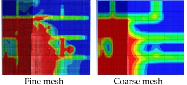
4.2. The influence of the meshing
Lagrange cells length size at approximatively the same computing time.
Fine mesh Coarse mesh
Fig. 7. The mesh size influence
Hence in order to optimize both the computing time and the accuracy of the model, the 3 mm of the cell dimension was used, both for the Lagrange and Euler solver. Lagrange cells length has a great influence upon the accuracy of pressure and damages location on the wall as shown in Fig. 7. Furthermore, interaction between Lagrange and Euler also depends on the cells dimensions.
4.3. Johnson-Holmquist model
To describe the behavior of the masonry under detonation the constitutive material model developed by Johnson and Holmquist Johnson (JH model) it was used (Johnson and Holmquist, 1993). The equivalent strength is expressed in terms of pressure, strain rate and damage. Pressure is expressed as function of volumetric strain and includes crushing effects. Damage is accumulated as a function of volumetric plastic deformation and pressure. Cohesion component of the equivalent strength degrades as accumulating damage. All the JH parameters of masonry and mortar are inspired from (Meyer, 2001), Table 2.
5. Results and discussions
5.1. Experimental results
Some observations can be noticed regarding the results of experimental tests. Firstly, the masonry wall destruction respects the
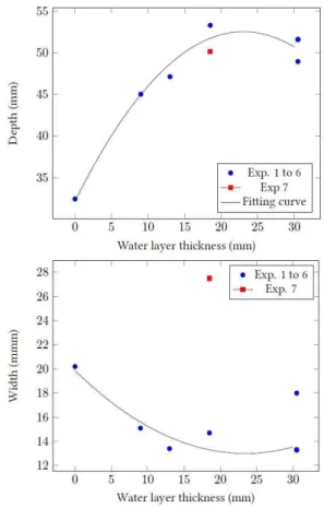
mechanism of brittle material under contact detonation, when a crater is formed on the placemet face of the charge. Also, craters do not present regular shape due to the non homogeneous wall structure. Then mortar near the crater is fully damaged and its state is as powder and fragment. The dimensions of the craters produced in the masonry walls by the explosions of the detonating cord are presented in Fig. 8. Data for experiment no. 7 has not been included in the fitting curve because it was obtained after a test performed in a different part of the wall.
Table 2. Parameters for masonry and mortar (after Meyer, 2011)
Parameters Brick Mortar
Density 1.986 1.604
Equation of state - polynomial
Bulk modulus (GPa) 5.3 1.7
Reference temperature (K) 288 288
Specific heat (J/kg·K) 640 640
Strength - continuous
Shear modulus (GPa) 5.18 1.15
Hugoniot elastic limit (GPa) 35.19 13.8 Cohesive strength coefficient A 0.6364 0.66 Pressure hardening coefficient N 0.8264 0.845
Strain rate coefficient C 0.0054 0.0018
Fractured strength coefficient B 1.568 1.335 Fractured strength exponent M 0.8 0.8 Maximum fracture strength ratio 17.33 80.24
Failure – continuous – damage gradual (JH)
Tensile strength (GPa) 0.006 0.0018
Damage constant D1 0.01413 0.00663
Damage constant D2 1.0 1.0
It can be seen an increase of the breach depth relatively to the increase of the water layer thickness, maximum value being reached between 20 and 30 mm of the water layer thichness. Regarding the influence of the water layer on breaches width, Fig. 8, it can be seen that there is a decrease of the breach width relatively to the increase of the water layer thickness. This can be interpreted as a concentration of the explosive charge action on a specific part of the wall.
reduced part of the wall so that it results the increase of the breach depth. This is confirmed by the fact that the minimum breach width and its maximum depth are caught for a water layer thickness around 25 mm.
Fig. 8. Breach dimensions relatively to the water layer thickness
5.2. Numerical results
The results of a numerical simulation for the first five cases of experimental cases (Table 1) are presented in Fig. 9. As it can be seen in Fig. 8 the damage zone increases with an increase of the water layer thickness, as in the experimental tests. Regarding the breach depth, it appears that it increases relatively to an increase of the water layer thickness. The breach has a maximum value at approximately 30 mm of water layer thickness, as shown in Fig. 10.
Although numerical simulations reveal the same trends concerning evolution of depth
relatively to the water layer thickness, one major point remains inexact. Indeed, the maximum increase of the depth relatively to a case without water layer is about to 3.5 mm (from 19 mm to 22.5 mm) where as in experimental case it was around 20 mm (from 33 mm to 53 mm). The differences regarding the breach depth can be explained by the Johnson-Holmquist parameters used for the material model. Thus, all parameters used in the material model were derived from the literature, depending on the compressive strength of brick and mortar only. Also, for experimentation was used an old masonry wall, which had non homogeneous local parameters that would have been modified by cracks or any air bubbles located in mortar joint or in brick units.
Case 1 Case 2
Case 3 Case 4
Case 5
Fig. 9. Results of the numerical simulations for the first five cases of experimental tests
depends on the water layer thickness, because it appears that breach borders are more blunted for little values of water layer thickness, that shows a kind of breach enlargement with a decrease of the water layer thickness. This confirms the concentration effect of the water layer on the explosive action.
Breach depth relatively to the water layer thickness
Breach profil relatively to the water layer thickness Fig. 10. Breach dimensions obtained by
numerical simulations
6. Conclusions Special explosive charges can be a safe and fast solution for breaching in masonry walls. The design of such an explosive charge requires not only knowledge about detonation and blast effects, but also regarding the behaviour of the material of the obstacle against which there is a need to perform a breach. The behavior of a masonry wall under contact detonation of the explosive charge of a breaching system is influenced by the many factors as: the strength of the brick unit or mortar, the placement of the explosive charge (on the
brick or on the mortar joint between bricks), the bricks arrangement, the presence of plaster and the quality of bricks and mortar joint. The experimental tests have confirmed the mechanism of wall destruction and permited to determine the influence of water layer thickness on the level of cratering. The water layer used in the breaching system to mitigate the aerial shock wave and fragments propulsion will modify also the mechanism of masonry wall destruction by increasing the depth and decrease the width of the crater as the increasing of the water layer thickness. The numerical simulations revealed the nessesity to determine the proper values for material models parameters in order to obtain right results. For contact detonation the influence of the strain rate should be taken into account.
REFERENCES
Moldovan M., Lupoae M., Baciu C., Constantin D. (2015),Breaching in light obstacles, Urbanism Architecture Constructions6(3): 35-44. Jiang F., Han F., Wang J., Xu Y. (2012),Experimental
Study of overpressure caused by counter-terrorist door breaching explosive, Transaction of Beijing Institute of Technology32(7): 665-668. Jiang F., Han F., Wang J. (2013),Numerical simulation
of non-contact explosion by door breaching explosive, Journal of Beijing Institute of Technology22(1): 1-5.
Lupoae M., Goga D., Constantin D., Baciu C., Moldovan M. (2011), Aspects regarding the water jet propulsion using explosive energy for door breaching, Lecture Notes in Engineering and Computer Science, World Congress on Engineering, London,3(2): 2138-2142. Akers S., Weed R., Rickman D., Danielson K. (2005),
Numerical Simulations of Explosive Wall Breaching, Proceedings of the High Performance Computing Modernization Program, Nashville, USA, pp. 202-206. Moldovan M., Enache C. (2015), The Influence of
Water Layer in Case of Explosive Breaching Devices,MTA Review35(3): 307-314. Wang M., Hao H., Ding Y., Li Z. (2009),Prediction of
masonry material properties, International Journal of Impact Engineering36(6): 808-820. Linse T., Gebbeken N., Araújo T., Silva R. (2012),
Experimental investigations and validation of a new material model developed for mansory bricks, Blucher Mechanical Engineering Proceedings1(1): 909-931.
Grote D., Park S., Zhou M. (2001),Dynamic behavior of concrete at high strain rates and pressures: I. experimental characterization, International Journal of Impact Engineering25(4): 869–886. Ross C., Thompson P., Tedesco J. (1989), Split Hopkinson pressure bar tests on concrete and mortar in tension and compression, ACI Materials Journal86(5): 475-481.
Cotsovos D., Pavlovic M. (2008), Numerical investigation of concrete subjected to high rates of uniaxial tensile loading, International Journal of Impact Engineering35(5): 319-335.
Riedel W., Kawai N., Kondo K. (2009), Numerical assessment for impact strength measurements in concrete materials, International Journal of Impact Engineering36(2): 283-293. Zhou X., Hao H. (2008), Modelling of compressive
behaviour of concrete-like materials at high strain rate, International Journal of Solids and Structures45(17): 4648–4661.
Hao H., Tarasov B. (2008), Experimental study of dynamic material properties of clay brick and mortar at different strain rates, Australian Journal of Structural Engineering 8(2): 117-132.
Benedetti A., Pelà L. (2012), Experimental characterization of mortar by testing on small specimens, Proceedings of the 15th International Brick and Block Masonry Conference, Florianópolis, Brazil, pp. 1-10. Pereira J., Dias A., Lourenço P. (2013), Dynamic
properties of clay brick at different strain rates, Proceedings of the 12th Canadian Masonry Symposium, Vancouver, Canada.
Sielicki P. (2013), Masonry failure under unusual impulse loading, PhD Dissertation, Poznan University of Technology, Poznan, Poland.
Wei X., Stewart M. (2011), Model validation and parametric study on the blast response of unreinforced brick masonry walls, International Journal of Impact Engineering37(11): 1150– 1159.
Meyers M. (1994), Dynamic behavior of materials, John Wiley and Sons, New York, USA. Lourenco P., Rots J. (1997), A multi-surface interface
model for the analysis of masonry structures, Journal of Engineering Mechanics 123(7): 660-668.
Pietruszczak S., Niu X. (1992), A mathematical description of macroscopic behavior of brick masonry, International Journal of Solids and Structures29(5): 531-546.
Chaimoon K., Attard M. (2007), Modelling of unreinforced masonry walls under shear and compression, Engineering Structures 29(12): 2056–2068.
Shieh-Beygi B., Pietruszczak S. (2008), Numerical analysis of structural masonry: mesoscale approach, Computers and Structures 86(21-22): 1958-1973.
Marques R., Lourenco P. (2011), Possibilities and comparison of structural component models for the seismic assessment of modern unreinforced masonry building, Computers and Structures89(21-22): 2079-2091. Ghiassi B., Soltani M., Tasnimi A. (2012),A simplified
model for analysis of unreinforced masonry shear walls under combined axial, shear and flexural loading, Engineering Structures 42(9): 396-409. Baloevic G., Radnic J., Harapin A. (2013),Numerical
dynamic tests of masonry-infilled RC frames, Engineering Structures50(5): 43-55.
Johnson G., Holmquist T. (1993), An Improved Computational Constitutive Model for Brittle Materials, Joint AIRA/APS Conference, Colorado Springs, Colorado, USA.
Meyer C. (2011),Development of Geomaterial Parameters for Numerical Simulations Using the Holmquist-Johnson-Cook Constitutive Model for Concrete, Technical Report, Army Research Laboratory, Aberdeen Proving Ground, MD, USA.
Received: 22 July 2016 •Revised: 2 August 2016 •Accepted: 22 August 2016