(Annals of the Brazilian Academy of Sciences) ISSN 0001-3765
www.scielo.br/aabc
A model for coupled electro-hydro-mechanical processes in fine grained soils accounting for gas generation and transport
CLAUDIO TAMAGNINI1, CRISTINA JOMMI2 and FABIO CATTANEO1 1Università degli Studi di Perugia, Department of Civil and Environmental Engineering
via G. Duranti 93, 06125 Perugia, Italy
2Politecnico di Milano, Department of Structural Engineering
piazza Leonardo da Vinci 32, 20133 Milano, Italy
Manuscript received on July 5, 2008; accepted for publication on May 18, 2009
ABSTRACT
A theoretical and numerical model is developed for the quantitative analysis of coupled processes taking place in active waste containment systems, such as electrokinetic barriers or fences, in which a low intensity DC current is circulated across the clay barrier to move polar and non-polar contaminants. A novel feature of the proposed approach is the allowance for the presence of air in the pore space. Under unsaturated conditions, all transport coefficients involved in the electrokinetic process are strongly dependent on the degree of saturation of pore liquid. In order to assess the predictive capability of the proposed theory and to appreciate the impact of gas production at the electrodes, a series of numerical simulations of simple one-dimensional electrokinetic tests have been performed. The results of the simulations compare reasonably well with data obtained from laboratory experiments performed on an illitic clayey silt. The numerical results indicate that the impact of gas production at the electrodes can be significant, even in low-intensity and short-duration treatments.
Key words: electro-osmosis, experimental investigation, theoretical model, finite element analysis, unsat-urated soils.
INTRODUCTION
In the last twenty years, the increased demand for innovative remediation technologies stimulated the development of electrokinetic treatments as a valuable tool for decontamination of clayey soils (Mitchell 1991, Yeung 1994, Alshawabkeh and Acar 1996).
To check the applicability of electrokinetic remediation, the various phenomena occurring in fine-grained soils upon application of a DC electric field, have been extensively studied (Acar et al. 1989, Acar and Alshawabkeh 1993, Virkutyte et al. 2002). Besides affecting pore water pressure regime by inducing in the soil mass a time-dependent coupled flow and deformation (consolidation) process, the application of
Selected paper presented at the IUTAM Symposium on Swelling and Shrinking of Porous Materials: From Colloid Science to Poromechanics – August 06-10 2007, LNCC/MCT.
an electric field to a fine-grained soil promotes complex electro-chemical phenomena, such as hydrolysis reactions at the electrodes, ion migration, changes in pore water pH, aqueous phase reactions, precipitation and dissolution, adsorption and desorption (Acar et al. 1990, Eykholt 1992, Eykholt and Daniel 1994, Acar and Alshawabkeh 1996, Alshawabkeh and Acar 1996, Yeung et al. 1997, Musso 2000, Alshawabkeh et al. 2004). These phenomena can, in turn, induce permanent modifications to the mechanical properties of the soil (Esrig and Gemeinhardt Jr. 1967, Gray 1970).
Besides electrokinetic remediation, the application of a DC electric field was proposed to realise active containment systems, such as electrokinetic barriers to enhance the performance of compacted clay liners, or electrokinetic fences for the manipulation and diversion of contaminant plumes in polluted sites (Mitchell 1991, Yeung et al. 1992, Yeung 1994). Electrokinetic barriers appear particularly promising in order to contrast the diffusive flow of contaminants through traditional liners for permanent containment. In this case, pollutants do not have to be removed from the soil mass, but simply prevented from migrating in the aquifer. Hence, a DC field is applied to counteract the migration of polluting species occurring because of diffusive and advective fluxes (seee.g., Yeung 1994).
Short-term duration of the treatment limits the effects of electrochemical reactions. The effects of the application of the DC field on the hydro-mechanical behaviour of the soil skeleton, if any, are expected to be mainly due to local desaturation following gas production during hydrolysis at the electrodes. In practical applications, the development of gas at the electrodes is not the only possible cause of loss of saturation. As a matter of fact, the soil used for the construction of clay liners is typically compacted in unsaturated conditions, while in polluted areas migration of contaminants often takes place in the unsaturated zone above the groundwater table. In any case, when the gas volume fraction in the pore space increases, the transport parameters involved in the electrokinetic process experience significant changes with the degree of saturation, and this might have a strong impact on the overall evolution of the electrokinetic treatment.
In spite of this observation, quantitative assessment of the impact of the degree of saturation on the evolution of electrokinetic processes does not appear to have been presented in the past, to the author’s knowledge. A few pilot tests were performed in unsaturated soil layers with the aim of verifying the optimum electro-chemical conditions for polluted soil remediation (Mattson et al. 2002, Wieczorek et al. 2005, Chang et al. 2006). Mattson et al. (2002) suggested a model for electrokinetic ion transport through unsaturated sands in which a power law, calibrated on their experimental results, was assumed to describe the dependence of effective diffusion coefficient and effective ionic mobility on the degree of saturation. The relationship between electrical conductivity and degree of saturation has been the object of different investigations (see, e.g., Mualem and Friedman 1991), while the work of de Wet (1995) provides a few laboratory data for the characterization of the electro-osmotic permeability in unsaturated conditions.
In this paper, a four-field theoretical model is presented for the quantitative analysis of the coupled flow and deformation processes taking place in unsaturated fine-grained soils during electrokinetic treat-ment, and its FE numerical implementation is briefly discussed. The model is developed under the sim-plifying assumptions of negligible chemical reactions and negligible changes in pore water pH and ionic concentrations of dissolved species. Numerical simulations of one-dimensional electrokinetic filtration and consolidation tests are presented, and the numerical results are compared to experimental data obtained in a series of laboratory electrokinetic filtration tests and electrokinetic consolidation tests, performed with an electrokinetic oedometer designed by Tamagnini (1994). Both experimental data and numerical results suggest that, for electrokinetic treatments of limited duration, the gas generated by electrolysis at the elec-trodes has a definite impact on the time evolution of the process.
THEORY
In the development of the theoretical model proposed for fully coupled electro-hydro-mechanical pro-cesses, which occur in fine-grained soils during a typical short-term electrokinetic treatment, the following assumptions are introduced:
i) in order to account for gas generation and transport, the soil is considered as a three-phase porous medium, with a deformable solid skeleton the pores of which are occupied by water and, possibly, gas;
ii) the solid skeleton deformation is governed by a hypo-elastic constitutive equation, defined in terms of a Bishop’s type effective stresses (Lewis and Schrefler 1998, Jommi 2000);
iii) the solid phase can be considered incompressible (ρs =const.);
iv) fluxes of mass and electric charge are quasi-linear functions of relevant potential gradients (conduction coefficients may change due to modifications in porosity, degree of saturation, etc.);
v) electrophoresis and streaming currents are negligible;
vi) the coupled conduction processes occur under isothermal conditions;
vii) no significant chemical reactions (precipitation, dissolution, aqueous phase reactions and sorption) occur during the entire duration of the process, except electrolysis at the electrodes;
viii) no significant changes in ionic concentrations of dissolved species in the pore fluid and in pore water pH occur during the entire duration of the process.
where low current densities are used and the duration of the process is relatively short, these assumptions can be considered a reasonable first-order approximation.
BALANCE EQUATIONS
The relevant balance equations for the three-phase porous continuum are derived following the approach of macroscale mixture theories of porous media (Panday and Corapcioglu 1989, Coussy 1995, de Boer 1995, Lewis and Schrefler 1998). Following the usual conventions in material mechanics, tractions and fluid pressures will be assumed positive. Boldface notation is adopted for vectors and tensors.
Balance of mass for the solid phase
In the absence of mass exchange between solid and liquid phases due to chemical reactions, the balance of mass equation for the solid phase reads:
−d sn
dt +(1−n)∇ ∙v
s =0, (1)
wheren =nw+ngis the soil porosity, sum of the volume fractions of the liquid (nw) and gas (ng) phases; vs is the spatial velocity of the solid skeleton and
ds dt(∙):=
∂
∂t(∙)+ ∇(∙)[v
s] (2)
is the material time derivative following the motion of the solid skeleton.
Balance of mass for water
LetSw :=nw/nbe the degree of saturation of the pore space with respect to water, and
ww =n Sw vw−vs
(3)
denote the seepage (Darcy) velocity of the liquid within the pores. The balance of mass equation for water reads:
Sw dsn
dt + n ρw
ds
dt (ρwSw)+n Sw∇ ∙v
s + ∇ ∙
ww+ 1
ρw
ww∙ ∇ρw =0, (4)
whereρw is the intrinsic density of water.
Combining equations (4) and (1) to eliminate the material time derivative of the porosity, and neglecting the spatial water density gradient, the balance of mass equation for water, eq. (4), reduces to:
Swn ρw
dsρw dt +n
dsSw
dt +Sw∇ ∙v
s + ∇ ∙ww =0. (5)
Balance of mass for gas species
LetSg :=ng/n =1−Swbe the degree of saturation of the pore space with respect to gas, and
wg =n Sg vg−vs
denote the seepage (Darcy) velocity of the gas within the pores. The balance of mass equation for gas reads:
(Sg+H Sw) dsn
dt + n ρg ds dt
ρg(Sg+H Sw) +n(Sg+H Sw)∇ ∙vs
+∇ ∙ wg+Hww+ 1
ρg
wg+Hww∙ ∇ρg=0,
(7)
whereρg is the intrinsic density of the gas, and H is Henry’s constant, accounting for gas solubility in
water.
Combining equations (7) and (1) to eliminate the material time derivative of the porosity, and neglecting the spatial gas density gradient, the balance of mass equation for gas reduces to:
n(Sg+H Sw) ρg
dsρg
dt +n ds
dt Sg+H Sw
+(Sg+H Sw)∇ ∙vs + ∇ ∙ wg+Hww
=0. (8)
Finally, observing that, from eq. (5)
Sw∇ ∙vs + ∇ ∙ww = − Swn
ρw dsρ
w
dt −n dsS
w
dt , (9)
eq. (8) can be further simplified as follows:
n(Sg+H Sw) ρg
dsρg
dt − n H Sw
ρw
dsρw dt +n
dsSg
dt +Sg∇ ∙v
s+ ∇ ∙wg=0. (10)
Balance of linear momentum for the mixture
For quasi-static deformation and flow processes, the balance of linear momentum in local form for the three-phase mixture reads:
∇ ∙σ+ρb=0, (11)
whereσ is the total stress tensor,bis the gravity acceleration,
ρ:=(1−n)ρs +n Swρw+n Sgρg (12)
is the mass per unit volume of the mixture, andρs is the intrinsic average density of the solid particles.
Balance of electric charge
In the presence of an external electric field, the balance of electric charge equation reads:
∇ ∙ j+∂Qe
∂t =0 (13)
where j is the electric current density, and Qe is the charge density per unit volume of the mixture.
Neglecting the electric capacitance of the soil, the source term in eq. (13) vanishes and the balance equation reduces to:
CONSTITUTIVE EQUATIONS
Closure of the coupled multiphysics conduction and deformation problem requires the introduction of suitable constitutive equations for the stress tensorσ, the degree of saturationSw, the densitiesρwandρg
of the liquid and gas phases, and the fluxesww,wgand j.
Solid skeleton
Under the assumption of linear kinematics, the constitutive equation of the solid skeleton is formulated in the following incremental form:
dσ′′=D σ′′,qdǫ (15)
after,e.g., Bolzon et al. (1996), Jommi (2000), Borja (2004). In eq. (15):
σ′′:=σ + Swpw+Sgpg
1=σ+ pg−Sws
1 (16)
is a Bishop’s type effective stress tensor, pw is the pore water pressure, pg is the pore gas pressure,
s := pg − pw is the matric suction, ǫ := sym∇us is the linearised deformation tensor, and D is the tangent stiffness of the solid skeleton, typically depending on the current effective stress stateσ′′and on a set of internal variablesq, which quantify the effects of previous loading and hydraulic history. Following
a standard practice in soil mechanics, stresses and fluid pressures, pw and pg are defined relative to the
atmospheric pressure.
To keep the formulation as simple as possible, in this work the solid skeleton has been assumed as an isotropic and hypoelastic material. Therefore, the tangent stiffness tensor assumes the following form:
D σ′′= Ks1⊗1+2Gs
I− 1
31⊗1
(17)
in which:
Ks :=
p′′
λ∗ (18a)
Gs :=
3(1−ν) 2(1+ν)
p′′
λ∗ (18b)
are the bulk and the shear tangent moduli of the solid skeleton, respectively,
p′′:= 1
3 trσ
′′= p+ S
wpw+Sgpg
= p+ pg−Sws
(19)
is the mean effective stress,νis Poisson ratio andλ∗is a logarithmic compressibility coefficient.
Fluid phases
Assuming a barotropic behaviour for water and gas, their intrinsic densities variation read:
1 ρw
dsρ
w
dt = 1 Kw
dsp
w
1 ρg
dsρ g
dt = 1 Kg
dsp g
dt (20b)
where Kw is the bulk modulus of the liquid, assumed constant, and Kg is the bulk modulus of the gas.
Identifying eq. (20b) with the equation of state of a perfect gas under isothermal conditions, it follows that:
Kg= pg+patm (21)
where patmis the atmospheric pressure.
Water retention properties of the solid skeleton
Available experimental evidence (see, e.g., Alonso et al. 1987, Romero et al. 1999) indicates that the degree of saturation of the soil with respect to the liquid phase,Sw, is a function of the suctions and of the hydraulic history of the soil. In this work, only monotonic desaturation processes are of interest. Hence, the simple reversible law proposed by van Genuchten (1980) is adopted:
Sw = ˆSw(s)= 1+ |αsws|nsw
−msw (for
s >0) (22)
in whichαsw,nswandmsware material constants.
Since Sw+Sg =(nw+ng)/n =1, from eq. (22) it follows that:
dsS
w dt =
dSˆw ds
dss
dt = − Cs
n
dsp g
dt − dsp
w dt
(23a)
dsSg
dt = − dSˆw
ds dss
dt = Cs
n
dspg
dt − dspw
dt
(23b)
In the above equation, the non-negative storage coefficient:
Cs := −n
dSˆw
ds (24)
represents the rate at which the volumetric fluid content decreases due to increasing suction.
Liquid phase flow
The constitutive equation for the liquid seepage velocity,ww, is provided by the generalised Darcy’s law for the liquid:
ww = − 1
μw
kw,relκ (∇pw−ρwb)−ke,relκe∇φ (25)
whereμw is the liquid viscosity,κ andkw,rel are the absolute and relative hydraulic permeabilities of the soil,κeandke,relare the absolute and relative electro-osmotic permeabilities of the soil, andφis the electric potential.
tensor (see,e.g., the review paper by Mitchell 1991). The minus sign in front of this term is motivated by the available experimental evidence, which indicates that electro-osmotic flows occurs from the anode to the cathode, opposite to the electric gradient.
Following a standard practice in unsaturated soil mechanics, in eq. (25) both hydraulic and electro-osmotic permeabilities are defined as products of an intrinsic permeability tensor, depending on the mi-crostructural properties of the porous medium, and a non-dimensional relative permeability coefficient, which accounts for the effects of partial saturation on soil conduction properties.
Relative permeabilities are increasing functions of the degree of saturation Sw. In the present work, based on available experimental data, the following simple power laws have been adopted for kw,rel and ke,rel:
kw,rel=aw(Sw)bw (26a)
ke,rel=ae(Sw)be (26b)
whereaw,bw,aeandbeare material constants.
Gas phase flow
The constitutive equation for the gas seepage velocity, wg, is provided by the following generalised
Darcy’s law for the gas phase:
wg= − 1
μg
kg,relκ ∇pg−ρgb
+H
− 1
μw
kw,relκ (∇pw−ρwb)−ke,relκe∇φ
(27)
whereμgis the gas viscosity, andkg,relis the relative permeability of the soil with respect to the gas flow. The second term on the right-hand side of eq. (27) accounts for the flow of gas dissolved in the liquid phase via Henry’s constant H.
Relative permeability of gas is a decreasing function of the water saturation degree. Consistently with the the previous choice for water, a power law was adopted to describe its variation:
kg,rel =ag(1−Sw)bg (28)
whereag,bgare material constants.
Electric flow
Neglecting the contribution of streaming currents produced by liquid flow – assumption (v) – the consti-tutive equation for the electric current density, j, is provided by the following generalised Ohm’s law for the porous medium:
j = −χ∗∇φ (29)
where χ∗ is the effective electric conductivity of the porous medium in unsaturated conditions. The
conductivity coefficient can be expressed as the sum of two terms (see,e.g., Mualem and Friedman 1991):
whereχsis the apparent electric conductivity of the solid skeleton,χbis the apparent electric conductivity
of bulk pore water under saturated conditions, andχrel(Sw)is the relative electric conductivity, accounting for the effects of partial saturation. The following power law, similar to eq. (26), has been assumed in this work (Mualem and Friedman 1991, Mattson et al. 2002):
χrel =aχ(Sw)bχ (31)
whereaχ andbχ are material constants.
GOVERNING EQUATIONS IN STRONG FORM
Taking into account the constitutive equations for the two fluids, eqs. (20), and the definitions of the constitutive stress (16) and of the storage coefficient (24), the balance equations (11), (5), (10) and (14) for the coupled flow and deformation problem can be recast as follows:
∇ ∙σ′′− ∇ pwSw+pgSg
+ρb=0 (32a)
(Cww+Cs)p˙w−Csp˙g+Sw∇ ∙vs+ ∇ ∙ww =0 (32b)
−(Cs +H Cww)p˙w+ Cgg+Cs
˙
pg+Sg∇ ∙vs+ ∇ ∙wg=0 (32c)
∇ ∙ j=0 (32d)
where:
Cww:= n Sw
Kw
(33a)
Cgg:=
n(Sg+H Sw) Kg
(33b)
and the flowsσ′′,ww,wg and j are expressed as functions of the primary unknown fieldsu =us (solid
displacement), pw (liquid pressure), pg (gas pressure), andφ (electric potential) through the constitutive
equations (17), (25), (27) and (29).
INITIAL AND BOUNDARY CONDITIONS
The primary unknown fields of the problem are the displacement vector,u(x,t), of the solid skeleton, the pore liquid pressure, pw(x,t), the pore gas pressure, pg(x,t), and the electric potential,φ (x). Assuming
initially saturated conditions, pg0 is set equal to pw0, which typically corresponds to a hydrostatic pore pressure distribution. The hypoelastic character of the constitutive equation (15) requires to specify the initial effective stress state:
σ′′(x,0)=σ′′0. (34)
duration of the process at the cathode. At the anode, the production of oxygen arising from electrolysis of water is simulated by relating the inward gas flow to the instantaneous electric current density:
−wg∙n=qg =Je
RT 4F pg
η (35)
where qg is the calculated gas inflow per unit area, Je is the inward electric current density, R is the
universal gas constant,T is the absolute temperature, and F is the Faraday’s constant.
The efficiency parameter,η≤ 1, is introduced to account for possible losses at the electrode, due to non-controlled concomitant chemical reactions.
FE IMPLEMENTATION
Following standard arguments – see,e.g., Hughes (1987) – the weak form of the coupled flow and deforma-tion problem is implemented. Introducing a suitable spatial discretisadeforma-tion of the domain into finite elements, a standard Galerkin FE approximations for the unknown fields u, pw, pg andφ leads to the following
matrix form of eqs. (32):
Fint(d)−Cswpw−Csgpg−Fext=0 (36a)
Cwsd˙ + Pw˙pw−Cwg˙pg+Hwpw+Cwφφ− Qextw =0 (36b)
Cgsd˙ −Cgw˙pw+Pgp˙g+Hgwpw+Hgpg+Cgφφ−Qextg =0 (36c)
Hφφ− Jext=0 (36d)
wheredis the nodal displacement vector; pwis the nodal pore liquid pressure vector; pgis the nodal pore
gas pressure vector; φis the nodal electric potential vector. The definition of the matrices Pw, Pg, Hw,
Hg, Hφ,Hgw,Cws,Csw,Cgs,Csg,Cwφ,Cgφand of the vectors Fint,Fext, Qextw , Q ext
g , J
extis provided in
the Appendix.
Matrix equations (36) define a differential-algebraic problem, which was implemented in the FE platform COMSOL Multiphysics v3.4. Quadratic elements have been adopted for the relevant primary fields, while time integration of the system has been performed using a built-in version of the large-scale DAE solver DASPK, using a fifth order, variable-step size, implicit backward differentiation formula (BDF). No stabilization techniques of the numerical procedure were adopted, in order to highlight insta-bilities of the physical process arising when gas production overcomes the amount of gas which can be transported in the same time interval. The choice is discussed by Jommi et al. (1997) and Jommi and Vaunat (1998).
EXPERIMENTAL PROGRAMME
EXPERIMENTAL EQUIPMENT
A number of short-duration electrokinetic tests have been performed in an electrokinetic oedometer origi-nally designed by Tamagnini (1994). A perspex lateral ring (with internal diameter of 80 mm), sufficiently rigid to provide the necessary lateral constraint to lateral deformations while preventing lateral electric and hydraulic flows, contains the soil specimen. A cylindrical perspex piston, freely moving within the lateral ring, is connected to the external loading frame by a stainless steel piston, and transmits the verti-cal load. A fixed perspex top cap, with a bellofram seal in the center, allows the stainless steel piston to move freely in the vertical direction while keeping the interior of the cell hydraulically isolated from the exterior. Back-pressure can be imposed to the sample from an hydraulic connection at the base, and the amount of water entering the specimen through the bottom porous plate is measured by means of a standard volume gauge.
In order to minimise lateral friction between the piston and the lateral ring, a layer of silicon grease is placed on the interior surface of the ring. The hydraulic connection between the specimen and the external reservoirs is achieved by two porous plates, with a diameter of 70 mm, acting as electrodes in electrokinetic tests. The original porous plates, made of sintered bronze, were replaced with porous graphite plates, in the current version of the apparatus, in order to guarantee a better control of the electrochemical processes taking place at the electrodes. To perform electrokinetic filtration or consolidation tests, the two graphite porous plates are connected to a DC power supply. Tests can be performed either controlling the imposed difference of potential at the electrodes, or the applied current density.
MATERIAL TESTED,TESTING PROGRAMME AND CALIBRATION OF PARAMETERS
The experimental tests were performed on a clayey silt from the site of Viadana, in the Po river valley. The soil is characterised by specific gravityGs =2.74, liquid limitwL =0.59, plasticity indexP I =0.30
and activity A = 0.9. The dry soil was mixed with distilled water at a water content of w0 = 0.280 and prepared by dynamic compaction to a target void ratio ofe0 = 0.89, directly into the cell where the electro-hydro-mechanical tests were performed. The as-compacted degree of saturation of the soil samples wasSw0=0.85.
Some of the tests were run on specimens saturated under back-pressure prior to the application of electric field, while the remaining tests were performed on specimens starting from the as-compacted conditions. In the latter case, the measurement of water flow and vertical displacement allowed for tracking the degree of saturation throughout the tests.
A few tests were run alternating controlled load steps, increasing vertical stress at null electrical potential (1σv>0,φ =0), and electrokinetic filtration steps at constant vertical load (1σv=0,1φ6=0), imposing free drainage at both ends of the specimen. The test results are described in detail in Gabrieli et al. (2008a, b). Only the most relevant data will be recalled here, in the light of the following numerical simulations.
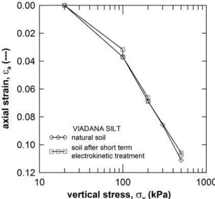
In Figure 1 the results of one-dimensional compression performed after short-term electrokinetic treat-ments are compared to similar data for the natural, saturated soil.
Fig. 1 – One-dimensional compression curves for natural and treated samples.
stiffness. This effect is quantitatively more pronounced at low stress levels, but it occurs systematically at all stress levels investigated. Nevertheless, when the treated sample is left under a constant load for a sufficient period of time – at least 24 hours – it recovers the same total strain as the untreated one, following an abrupt volume reduction taking place 5 to 10 hours after the application of the load increment. Systematic repeatability of the observation at increasing stress level suggests that reversible processes are taking place during short-term electrokinetic treatments.
The observed behaviour is thought to be a consequence of the gas production associated to electrolysis of water. The oxygen generated at the anode cannot escape easily from the sample, as it is entrapped by the water flowing into the sample. When the electric field is removed and a load increment is applied, the direction of the water flow is reversed and the entrapped air may eventually flow out from the sample with the aid of the load-induced water flow. If the sample, or at least a part of it, partially desaturates due to gas generation, capillary forces arise, which could be responsible for an increase in the soil stiffness. As the gas escapes, full saturation is recovered and the temporary increase in stiffness is lost.
In Figure 2 the evolution of the semi-logarithmic compliance,λ, of the treated sample with the duration of the electrokinetic treatment is shown.
The longer the duration of the treatment, the higher is the reduction in the degree of saturation that can be expected due to gas production. Such decrease in Sw is consistent with the observed reduction of soil compliance. These data allowed to calibrate the hypoelastic law (18), withλ∗=0.062 andν =0.3.
The time evolution of vertical displacements during a purely mechanical consolidation step applied to a saturated sample at null electric field was back-analysed to determine the hydraulic conductivity of the soil, as depicted in Figure 3.
Fig. 2 – Logarithmic complianceλvs. duration of the electrokinetic treatment, at constant vertical stress.
Fig. 3 – Measured and predicted consolidation curves for a single mechanical load increment at null electric field.
The relative hydraulic conductivity with respect to water, kw,rel, has been assumed to be given by eq. (26a), withaw =1 andbw =5, as suggested by the experimental data presented in Caruso and Jommi (2005). Consistently, in the relationship (28), describing the relative permeability with respect to gas, kg,rel, the constantsag=1 andbg=5 were assumed.
Electrokinetic filtration steps were performed at constant electric field, under constant vertical stress ranging fromσv = 20 kPa up to σv = 500 kPa and constant back pressure, to determine the electro-osmotic permeability (Gabrieli et al. 2008a). The imposed electric field and duration of the tests were chosen to be comparable to those adopted in the in-situ electrokinetic fencing application reported by Narasimhan and Sri Ranjan (2000). The measured electro-osmotic permeability isκe=0.9×10⁻⁹m2/(Vs).
was observed, indicating that, within the stress range investigated, the electro-osmotic permeability can be considered practically independent of the void ratio (in the range 0.8≤e≤0.9).
The dependence of the electro-osmotic permeability on the degree of saturation was investigated starting from the experimental results obtained by Gabrieli et al. (2008b) in electrokinetic filtration tests performed on unsaturated specimens in the as-compacted state. The experimental results obtained compare well with the results reported by de Wet (1995), as shown in Figure 4.
Fig. 4 – Relative electro-osmotic permeability: experimental data from de Wet (1995) and Gabrieli et al. (2008b).
The two data sets suggest that the relative electro-osmotic permeability,ke,rel, can be given as a function of the degree of saturation by the power law of eq. (26b), withae=1 andbe =3.2.
From the measurements of electric current densities during the electrokinetic filtration tests, an effective saturated bulk electrical conductivity, χ∗ = 0.109 S/m, has been estimated. The apparent con-ductivity of the soil skeleton was assumed to be negligible. The relative electrical concon-ductivity, χrel, was assumed to depend on the degree of saturation according to eq. (31), withaχ =1 andbχ =2, as suggested by literature experimental data (seee.g., Mualem and Friedman 1991, Mattson et al. 2002).
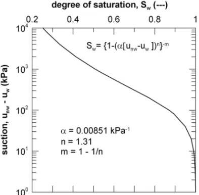
The characterisation of the hydraulic properties of Viadana silt is completed by the soil-water retention curve shown in Figure 5, derived from experimental results given by Caruso and Jommi (2005).
The experimental data are well interpolated by the curve described by (22), withαsw =0.00851 kPa−1, nsw =1.31 andmsw =1−1/nsw.
NUMERICAL SIMULATIONS
electric field and assuming free drainage at the cathode and no hydraulic flow at the anode (impervious boundary).
Fig. 5 – Soil-water retention curve for Viadana silt, after Caruso and Jommi (2005).
ELECTROKINETIC FILTRATION TEST
The ideal scheme for a one-dimensional electrokinetic filtration test on a saturated soil specimen is repre-sented in Figure 6.
Fig. 6 – Ideal scheme of one-dimensional electrokinetic filtration test on a saturated soil specimen.
By imposing a constant potential difference through the specimen, a uniform water flux is induced due to electro-osmosis. If the material is assumed to be fully saturated, the solution is characterised by constant pore water pressure, and uniform water flow is recovered. The water pressure remains constant and equal to the back-pressure imposed at the specimen draining boundaries.
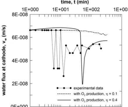
performed to evaluate the influence of the efficiency parameter η on the overall evolution of the water outflow at the cathode.
In Figure 7, the time evolution of the computed values of the vertical seepage velocity ww at the cathode, obtained with two different values of the efficiency parameter η, are compared with the ex-perimental data from an electrokinetic filtration test performed on an initially saturated specimen under the same electric potential difference.
Fig. 7 – Electrokinetic filtration test: comparison between experimental data and numerical simulations.
The experimental data clearly show that the initial flow rate tends to decrease as the duration of the test increases. In the numerical simulations, the decrease of the flow rate is associated to the progressive desaturation at the anode due to gas production. The outflow rate clearly depends on the amount of gas produced, as shown by the comparison between the two different numerical simulations. By increasing the amount of gas produced at the anode, an unstable outflow rate can be observed both from the experimental data and the numerical results. The numerical instability could be reduced by introducing a convenient minimum threshold for the hydraulic permeability to gas. Nonetheless, as pointed out previously, here the choice not to introduce numerical procedures to stabilise the simulation of an inherently unstable physical process was followed (Jommi and Vaunat 1998).
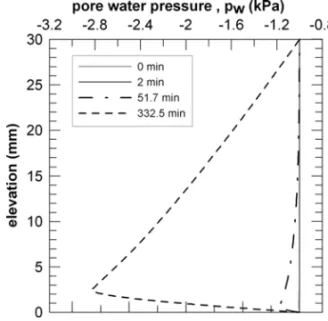
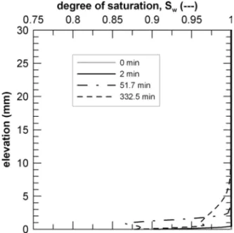
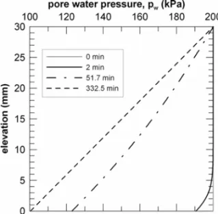
The isochrones of water pressure and of degree of saturation, obtained in the two numerical simulations, are shown in Figures 8 to 11.
The results indicate that, due to gas generation, the water pressure does not remain constant throughout the sample, although pore pressure variations remain relatively small. For the duration of the test considered, the advancing desaturation front only affects a small portion of the specimen close to the anode.
ELECTROKINETIC CONSOLIDATION TEST
Fig. 8 – Electrokinetic filtration test: isochrones of pore water pressure computed forη=0.1.
Fig. 9 – Electrokinetic filtration test: isochrones of the degree of saturation computed forη=0.1.
Fig. 11 – Electrokinetic filtration test: isochrones of the degree of saturation computed forη=0.4.
The ideal scheme for a one-dimensional electrokinetic consolidation test on a saturated soil specimen is represented in Figure 12.
Fig. 12 – Ideal scheme of one-dimensional electrokinetic consolidation test on a saturated soil specimen.
If water drainage at the anode is prevented when the electric field is applied, a water pressure gradient must develop to counteract locally the electro-osmotic induced flow. Water can flow out from the sample at the draining cathodic boundary only if an equal amount of pore volume reduction is induced by soil skeleton deformation. As the drainage process is controlled by the volumetric deformation rate of the soil skeleton, which in turns depends on the changes in vertical effective stress, the specimen undergoes a time-dependent deformation process whose time evolution is ruled by soil hydraulic conductivity, soil stiffness and specimen size. Neglecting gravity effects, the final stationary conditions are expected to be characterised by a constant pore pressure gradient and null water flow, so that, in the vertical direction,
ww = − 1
μw
κ∇pw−κe∇φ =0 (37)
throughout the specimen.
Numerical results are compared to actual experimental data from an electrokinetic consolidation test performed on a sample of Viadana silt in Figure 13, which shows the time evolution of pore water pressure at the anode.
Fig. 13 – Electrokinetic consolidation test: water pressure at the anodevs.time.
It is worth mentioning that the electrokinetic consolidation test was performed under an initial back pressure of 200 kPa. The initial back pressure was imposed to dissolve at least part of the gas generated at the anode, and to keep the sample as near as possible to fully saturated conditions. The water pressure at the bottom of sample (on the anodic side) and the vertical displacement at the top were measured during the whole duration of the test.
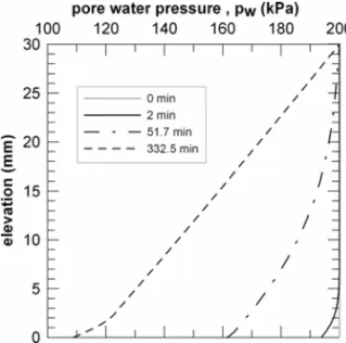
The comparison indicates that the decrease of pore water pressure at the anode is only slightly influenced by gas production. Nevertheless, the presence of gas affects the shape of the isochrones of pore water pressure in the sample, as shown in Figures 14 to 16.
Fig. 15 – Electrokinetic consolidation test: isochrones of water pressure for gas production at the anode withη=0.1.
Fig. 16 – Electrokinetic consolidation test: isochrones of water pressure for gas production at the anode withη=0.4.
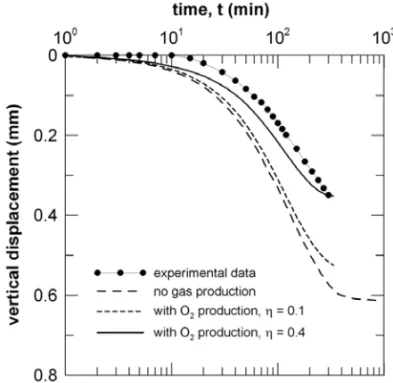
From the shape of the pore water pressure isochrones it can be observed that, while for the three simulations the computed pore water pressures at the anode are comparable, the computed values of pore water pressure within the sample tend to increase as gas production at the anode increases. This has a significant impact on the computed vertical effective stress field, and therefore on the computed vertical strain and displacement field. This is clearly shown in Figure 17, where the vertical displacement computed at the top surface of the specimen in the three simulations is plotted as a function of the elapsed time. In the figure, the vertical displacement recorded in the actual experiment is also reported.
The comparison between experimental data and numerical results indicates that, the higher the amount of gas produced at the electrode, the stiffer the system, consistently with the expected role played by suction on the mechanical behaviour of the coupled system.
Fig. 17 – Electrokinetic consolidation test: vertical displacement at the top surface of the specimenvs. time.
and experimental results is obtained with an efficiency factor η = 0.4. Differences between measured and predicted pore water pressures may be ascribed to a slight underestimation of hydraulic conductivity at high saturation degrees.
CONCLUSIONS
A theoretical model was developed to perform a quantitative analysis of coupled deformation and flow processes, occurring during low-intensity and short-duration electrokinetic treatments characterising the design of electrokinetic barriers and fences for pollutant migration control. The model has been implemented numerically using the finite element method, and adopting a monolithic approach.
A novel feature of the model is the possibility to take into account the effects of partial saturation on the electric, water and gas flows within the porous medium, and on the mechanical response of the soil skeleton. A set of suitable constitutive laws was formulated in terms of suction and degree of saturation, based on the results of an ongoing experimental programme, in order to cope with the experimentally observed variation of the mechanical, electrical, hydraulic and electro-osmotic conduction properties of the soil.
In a series of numerical simulations of one-dimensional electrokinetic filtration and consolidation tests, the proposed model was used to assess the role played by gas generation at the electrodes by electrolysis and its effects on the transport processes through the soil. Numerical predictions are compared to experimental data obtained in laboratory electrokinetic filtration tests and electrokinetic consolidation tests. The formu-lation helps in the interpretation of the experimental tests, and it captures quite well the relevant features of the observed behaviour.
definite impact on the time evolution of the process, affecting the hydraulic, electro-osmotic and electrical conduction properties, as well as on the soil skeleton stiffness.
The proposed model can be further used as an interpretative tool for ongoing experimental tests. Besides, it can be introduced as a design tool for the development of the electrokinetic barrier technology, to provide useful indications about the optimal design parameters, electrode geometry, applied voltage and time of treatment.
ACKNOWLEDGMENTS
The financial support of the Italian Ministry of University and Research, through the grant PRIN 2006080119-2006,Experimental and theoretical study of the applicability of electrokinetic processes for the control of contaminant propagation in fine grained soils, is gratefully acknowledged.
RESUMO
Um modelo teórico e computacional é desenvolvido para a análise quantitativa de processos acoplados que tomam lugar em sistemas de contenção de lixo tais como barreiras ou grades eletrocinéticas no qual uma DC corrente de baixa intensidade é circulada através da barreira de argila para movimentar contaminantes polares e não polares. Uma nova característica da abordagem proposta é permitir a presença de ar nos poros. Sob condições não saturadas todos os coeficientes de transporte envolvidos nos processos eletrocinéticos são fortemente dependentes do grau de saturação do líquido. Com o objetivo de avaliar a capacidade do modelo proposto de predizer e de apreciar o impacto da produção de gás nos eletrodos uma série de simulações numéricas foi realizada em testes eletrocinéticos simples unidimensionais. Os resultados das simulações concordam razoavelmente bem com dados experimentais obtidos em experimentos de laboratório realizados em argilas. Os resultados numéricos indicam que o impacto da produção de gás nos eletrodos pode ser significativo mesmo em tratamentos de baixa intensidade e curta duração.
Palavras-chave: eletro-osmose, investigação experimental, modelo teórico, análise de elementos finitos, solos não saturados.
REFERENCES
ACARYBANDALSHAWABKEHAN. 1993. Principles of electrokinetic remediation. Environ Sci Technol 27(13): 2638–2647.
ACAR YB AND ALSHAWABKEH AN. 1996. Electrokinetic remediation. I: Pilot-scale tests with lead-spiked kaolinite. J Geotech Engrg 122(3): 173–185.
ACARYB, GALERJ, PUTNAMGAANDHAMEDJ. 1989. Electrochemical processing of soils: its potential use in environmental geotechnology and significance of pH gradients. In: 2ND INTSYMP ONENVIR
GEOTECHNOL-OGY. Envo Publishing 1, p. 25–38.
ACARYB, GALERJ, PUTNAMGA, HAMEDJANDWONGRL. 1990. Electrochemical processing of soils: Theory of pH gradient development by diffusion, migration, and linear convection. J Env Sci Health A25: 687–714.
ALONSOEE, GENSAANDHIGHTDW. 1987. Special problem soils. General report. In: PROCIX ECSMFE, Dublin, Ireland. Balkema, Rotterdam, p. 1087–1146.
ALSHAWABKEHAN ANDACARYB. 1996. Electrokinetic remediation. II: Theoretical model. J Geotech Engng ASCE 122(3): 186–196.
ALSHAWABKEHAN, SHEAHANTCANDWUX. 2004. Coupling of electrochemical and mechanical processes in soils under DC fields. Mech Mater 36(5-6): 453–465.
BOLZON G, SCHREFLER BA AND ZIENKIEWICZOC. 1996. Elastoplastic soil constitutive laws generalized to partially saturated states. Géotechnique 46: 279–289.
BORJA R. 2004. Cam-clay plasticity. Part V: A mathematical framework for three-phase deformation and strain localization analyses of partially saturated porous media. Comp Meth Appl Mech Engng 193: 5301–5338.
CARUSOM AND JOMMI C. 2005. An evaluation of indirect methods for the estimation of hydraulic properties of unsaturated soils. In: BILSENHANDNALBANTOGLUZ (Eds), Problematic Soils. Eastern Mediterranean University Press 1, p. 183–191.
CHANGJH, QIANGZANDHUANGCP. 2006. Remediation and stimulation of selected chlorinated organic solvents in unsaturated soil by a specific enhanced electrokinetics. Colloid Surface A 287(1-3): 86–93.
COUSSYO. 1995. Mechanics of Porous Continua. J Wiley & Sons, NY, USA.
DEBOERR. 1995. Theory of Porous Media. Springer, Berlin.
DEWET M. 1995. Electro-kinetics, infiltration and unsaturated flow. In: ALONSO E AND DELAGEP (Eds), Unsaturated Soils. A.A. Balkema, Rotterdam 1, p. 283–291.
ESRIG MANDGEMEINHARDTJRJ. 1967. Electrokinetic stabilisation of an illitic Clay. J Soil Mech Found Div ASCE 93(3): 109–128.
EYKOLTG. 1992. Driving and complicating features of the electrokinetic treatment of contaminated soil. Ph.D. Thesis, University of Texas at Austin, Texas.
EYKHOLTGR AND DANIELDE. 1994. Impact of system chemistry on electroosmosis in contaminated soil. J Geotech Engng, ASCE 120: 797–815.
GABRIELIL, JOMMIC, MUSSOGANDROMEROE. 2008a. Influence of electroosmotic treatment on the hydro-mechanical behaviour of clayey silts: preliminary experimental results. J Appl Electrochem 38: 1043–1051.
GABRIELI L, JOMMIC, MUSSOGANDROMEROE. 2008b. Electrokinetic treatment of a natural silt in saturated and unsaturated conditions. In: SHAO JF AND BURLION N (Eds), Thermo-hydromechanical and Chemical Coupling in Geomaterials and Applications: Proceedings of the 3rd International Symposium GeoProc2008. Wiley, ISTE, p. 203–210.
GRAYDH. 1970. Electrochemical hardening of clay soils. Géotechnique 20: 81–93.
HUGHESTJR. 1987. The Finite Element Method. Prentice-Hall, Englewood Cliffs.
JOMMIC ANDVAUNAT J. 1998. A note on finite element modelling of unsaturated consolidation problems. In: CIVIDINI A (Ed), Application of Numerical Methods to Geotechnical Problems, NUMGE98. CISM, Udine, p. 315–326.
JOMMI D, VAUNAT J, GENS A, GAWIND AND SCHREFLER BA. 1997. Multiphase flow in porous media: a numerical benchmark. In: Proceedings of NAFEMS World Congress 97, 2, p. 1338–1349.
LEWIS RW AND SCHREFLER BA. 1998. The Finite Element Method in the Static and Dynamic Deformation and Consolidation of Porous Media. J Wiley & Sons, NY, USA.
MATTSONED, BOWMANRSANDLINDGRENER. 2002. Electrokinetic ion transport through unsaturated soil: 1. Theory, model development, and testing. J Contam Hydrol 54(1-2): 99–120.
MITCHELLJK 1991. Conduction phenomena: from theory to geotechnical practice. Géotechnique 41: 229–340.
MITCHELLJK. 1993. Fundamentals of Soil Behavior. 2nded., J Wiley & Sons, NY, USA.
MUALEMYANDFRIEDMANS. 1991. Theoretical prediction of electrical conductivity in saturated and unsaturated soil. Water Resour Res 27(10): 2771–2777.
MUSSOG. 2000. Electrokinetic phenomena in soils. Ph.D. Thesis, Politecnico di Torino.
NARASIMHANBANDSRIRANJANR. 2000. Electrokinetic barrier to prevent subsurface contaminant migration: theoretical model development and validation. J Contam Hydrol 42(1): 1–17.
PANDAYSANDCORAPCIOGLUMY. 1989. Reservoir transport by compositional approach. Transport Porous Med 4: 369–393.
ROMEROE, GENSAANDLLORETA. 1999. Water permeability, water retention and microstructure of unsaturated compacted boom Clay. Eng Geol 54: 117–127.
TAMAGNINIC. 1994. Electrokinetic phenomena in clayey soils and electrokinetic consolidation theory: experimental investigation and numerical modelling (in italian). Ph.D. Thesis, Università degli Studi di Roma la Sapienza.
VANGENUCHTENMT. 1980. A closed form equation for predicting the hydraulic conductivity of unsaturated soils. Soil Sci Soc Am J 44: 892–898.
VIRKUTYTEJ, SILLANPÄÄMANDLATOSTENMAAP. 2002. Electrokinetic soil remediation – critical overview. Sci Total Environ 298(1-3): 97–121.
WIECZOREKS, WEIGAND H, SCHMIDMAND MARBC. 2005. Electrokinetic remediation of an electroplating site: design and scale-up for anin-situapplication in the unsaturated zone. Eng Geol 77(3-4): 203–215.
YEUNG AT. 1994. Electrokinetic flow processes in porous media and their applications. In: CORAPCIOGLUMY (Ed), Advances in Porous Media 2: 309–395.
YEUNG AT AND MITCHELL JK. 1993. Coupled fluid, electrical and chemical flows in soil. Géotechnique 43: 121–134.
YEUNGAT, SADEKSMANDMITCHELLJK. 1992. A new apparatus for the evaluation of electrokinetic processes in hazardous waste management. Geotech Testing J 15: 207–216.
APPENDIX
LetNf be the interpolation functions adopted for the generic primary field f, and let Bu, Ep, Eφ be the
discrete gradient operators, such that:
sym∇uh= Bud ∇pwh = Eppw ∇pgh= Eppg ∇φh =Eφφ
withmbeing the second-order unit tensor in Voigt notation:
m:=
1 1 1 0 0 0 T
Then, the FE matrices appearing in eqs. (36) are given by:
Pw := Z
B
(Cww+Cs)NpTNpdv Pg:=
Z
B
Cgg+Cs
NpTNpdv
Hw := Z B EpT k w,rel μw κ
Epdv Hg:=
Z
B
EpT
k
g,rel μg
κ
Epdv
Hgw := Z
B
EpT
H kw,rel μw
κ
Epdv Hφ:=
Z
B
EφTχ∗Eφdv
Csw := Z
B
SwBuTm Npdv Cws :=
Z
B
Sw NpTmTBudv =CsTw
Csg:=
Z
B
SgBuTm Npdv Cgs:=
Z
B
SgNpTmTBudv=CTsg
Cwφ := Z
B
EpT ke,relκe
Eφdv Cgφ:=
Z
B
EpT H ke,relκe
Eφdv
and the FE vectors appearing in eqs. (36) are given by:
Fint(d):=
Z
B
BuTσ′′dv
Fext :=
Z
B
ρNuTbdv+
Z
∂Bt
NuTtda
Qextw :=
Z
B
EpT
kw,rel
μw
κ
(ρwb) dv+ Z
∂Bqw
NpTqwda
Qextg :=
Z
B
EpT
kg,rel
μg κ
ρgb
dv + Z B EpT
H kw,rel μw κ
(ρwb) dv+ Z
∂Bqg
NpTqgda
Jext :=
Z
∂Bj
NφTJeda