Abstract A combination of computational models and
theoretical methods have been developed and used to study the contact of hip resurfacing devices under normal/central and edge loading conditions. The techniques have been developed and the solutions are based on using the finite element method. It has been found that the study of hip joint modelling, numerical methodologies of mechanical wear simulations and shakedown analysis can be developed to study the contact mechanics and biotribology of hip resurfacing devices under central and edge loading conditions. Each method developed in this study provides a unique platform to study these problems.
Index Terms Biotribology, contact, finite element analysis,
shakedown, wear.
I. INTRODUCTION
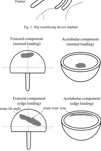
ontact mechanics, wear and surface damage of hip resurfacing devices (Fig.1) are subjects which have been studied since very early implantations. The wear and surface damage of these bearing surfaces occur through normal gait loading conditions in-vivo (after being implanted into patients). Another particular problem is the stripe wear patterns observed on both metal-on-metal (MOM) and ceramic-on-ceramic (COC) patient retrievals [1], [2] and devices which have been tested usingin-vitromethods such as a hip simulator [3], [4]. It has been claimed that edge loading occurs during the walking cycle of the patient; therefore microseperation is simulated into each cycle during experimental wear testing [5]. The laxity of the hip joint is known to lead to microseperation during the gait cycle, and fluoroscopy studies have revealed how edge loading of the hip joint is caused by lateral sliding of the femoral component during gait [5], [6]. The differences between wear patterns observed during normal and edge loading conditions for the femoral head and acetabular cup is shown schematically in Fig. 2. The stripe tilt angle is related to the anteversion of the cup located in the pelvis.
This study expands on the research conducted previously by Ali and Mao [7] by developing techniques to assess both the contact mechanics for wear modelling wear and the application of shakedown theory to cyclically loaded hip resurfacing devices, particularly those under normal loading and microseperation conditions leading to edge loaded hip resurfaced bearings.
Manuscript received October 24, 2012; revised October 31, 2012. This work was supported and funded by the EPSRC (Engineering and Physical Sciences Research Council).
M. Ali is with the School of Engineering, University of Warwick, Coventry, CV4 7AL, UK (e-mail: [email protected]).
K. Mao is with the School of Engineering, University of Warwick, Coventry, CV4 7AL, UK (e-mail: [email protected]).
Acetabular cup Femoral head
Femur
Pelvis
Fig. 1. Hip resurfacing device implant
Femoral component (normal loading)
Femoral component (edge loading)
Acetabular component (normal loading)
Acetabular component (edge loading)
stripe wear zone stripe tilt angle
Fig. 2. Hip resurfacing device normal and edge loading wear
II. CONTACT, WEAR AND SHAKEDOWN
The subject of contact mechanics, wear assessments and the application of shakedown theory have been studied to improve the performance of engineering component design where cyclic loading occurs. This study specifically focuses on the hip resurfacing device and each of these three subjects are relevant to the application and related to one another. These three subjects will be discussed along with the explanation of its relevance to bearing hip resurfacing devices.
Contact Analysis of Hip Resurfacing Devices
under Normal and Edge Loading Conditions
Murat Ali and Ken Mao
A. Contact Mechanics
In this study contact mechanics forms the basis of the solutions presented, it is therefore important to understand contact mechanics and its application to solving contact, wear and shakedown analysis associated with hip resurfacing devices. For spherical bodies in normal contact, a circular contact patch will be observed as expressed by (1) [8] where p is the contact pressure, po is the maximum contact
pressure,ris the radius of contact patch,ais the maximum contact radius (Fig. 3a) and n a value defined to represent uniform pressure, uniform normal displacement and Hertz pressure. The contact area will be elliptical if the bodies in contact are non-conforming as expressed by (2) [8] where the maximum contact radiusbis in theydirection (Fig. 3b). As the acetabular cup and femoral head components contact each other at multiple points before any deformation takes place, the contact can be defined as conforming. Two bodies contacting at one point (elastic half space) is typical of non-conforming contact which leads to the formation of Hertzian contact [9]. Therefore, to adapt the theory to be applicable to hip joints (ball-in-socket joints) the formulation is extended to consider angular coordinates.
n o
a
r
p
p
1
22 (1)
2 / 1 2 2
1
,
b
y
a
x
p
y
x
p
o (2)y
r a
y
a b
(a ) (b)
x
x
Po(y)
a
a
x
y
(c)
Fig. 3. Contact area for (a) circular contact (b) elliptical contact (c) theoretical edge loading contact [8]
The study of contact pressure distribution at the end of component contact has been studied theoretically as an elastic half body with a radius end on a flat elastic body (Fig. 3c). This formulation can form the basis for edge loading contact theory for hip resurfacing devices where the contact pressure distribution differs to that of circular or elliptical contact.
B. Finite Element Modelling
For a static analysis, the time dependant effects of damping and inertia do not have a significant effect to the response of the hip joint structure. The basis of a finite element static analysis is given by (3), where {F} is the force vector, [K] is the stiffness matrix and {u} is the displacement vector. A static analysis can be performed which includes both normal and edge loading contact, under the assumption that the load is applied gradually to ensure an accurate solution is reached. This can involve using displacement control to establish contact before load control is initiated. This methodology needs to be carefully applied to ensure that valid boundary conditions simulate the realistic hip joint normal and edge loading kinematics.
F
K
u
(3)Although static and quasi-static analysis is most often the modelling assumption made for hip joint contact problems, the hip joint in reality behaves dynamically under the action of a load or displacement. If the application of the load or displacement is slow enough, the system can be assumed to be loaded and respond statically as the inertial forces can be neglected. The importance of considering both static and dynamic loading has been studied for implanted hip joints [10], [11]. Both the static and dynamic analysis can be considered for linear and non-linear systems; however some limitations in computational techniques may mean that simplifying assumptions are required. The basis of dynamic equilibrium includes inertia effects and can be represented by (4), where M, u and I are the mass, acceleration and internal force of the structure respectively and L is the externally applied load.
L I u
M
..
(4)
An implicit finite element solver can determine the unknowns {u} and obtain equilibrium whilst including the effects of damping and inertia. In order to make a sensible choice on opting for implicit or explicit methods, one must consider if the solution to the problem is time dependant. In an implicit method, the mass and damping factors can be ignored because the displacement is not a function of time. The velocities and accelerations are also zero, because the derivatives of the displacement are zero. Implicit solutions often involve very large global stiffness matrices which are required to be inverted and can therefore be memory intensive. Numerical methods such as the Newton Raphson method are used to solve the implicit finite element problems. The explicit method considers the solution to be a function of time, therefore both velocity and acceleration are included which means mass and damping affects are considered. For the explicit method a central difference method time integration scheme is used. The scheme calculates the field variables at the nodal points and the method works by inverting the lumped mass matrix. The basis of the solution works on time step increments.
Numerical contact modelling as a whole through the finite element method has provided solutions to contact problems
within the orthopaedic device industry. The contact algorithms considered in this study are based on finite sliding interactions, where one of the sliding interfaces was defined as the slave surface and the other as a master surface. This formulation is especially suitable for hip resurfacing devices under gait motion where large sliding distances relative to the radius of contact are expected. A surface-to-surface descritization method allows for accurate contact between the deformable bodies and would be the preferable choice over node-to-node contact. To consider the friction between the contact surfaces a tangential interaction property can be defined which is based on an isotropic coulomb friction model. This tangential definition models the shear forces between the femoral head and acetabular cup, whereas the normal contact behaviour can be modelled as hard contact. This contact formulation provides the foundations for advanced contact analysis between the hip bearing components.
Past studies have considered the contact stresses on the surface of the hip bearing components, and a number of inspection techniques have been used to assess the surface wear zones [12], [13]. Very few studies assess the subsurface at these subsurface zones. In one study, the subsurface structure of metal-on-metal hip implants have been inspected at the primary wear zones (under normal ISO gait loading conditions) and stripe wear zones (under swing phase load conditions) during experimental simulator testing. The subsurface assessments of both experimentally tested components and patient retrievals show similar microstructures following testing and patient usage. There were no significant differences between the subsurface microstructure changes in the primary and stripe wear zones [14].
C. Wear Modelling
For studying mechanical wear of orthopaedic devices, the Archard wear model [15] has been used with finite element analysis techniques. Although the Archard wear model appears in many forms, the form most appropriate to be used within the finite element method has been described by (5) [16] where his the linear wear depth,kwis the dimensional
wear coefficient (mm3/N mm),pis the contact stress andsis the sliding distance. This is the simplest and most widely used abrasive wear model.
ps
k
h
w (5)D. Shakedown Theory
For hip bearing components under cyclic loading any residual stresses can act to protect the component from plastic deformation by ensuring purely elastic material behaviour is reached in the longer term. It is possible that shakedown theory (Fig. 4) can be applied to both contact surfaces at the global level as well as the micro asperity level between two devices in contact [17], and the theory can also be applied to assess the repetitive rolling and sliding contacts for elastic-perfectly plastic materials [18]. For
ductile materials an idealisation and assumption can be made which defines the material to have elastic-perfectly plastic material properties. The transition from elastic to perfectly plastic materials properties occurs at the yield point of the stress-strain curve and this assumes that the material does not harden under loading conditions. Results from experimental hip simulator studies have shown an increase in surface roughness as the number of contact cycles increase, which can further justify the application of shakedown theory especially at the asperity level.
Shakedown theory is based on Koiter s and Melan s theorems. Where Koiter s theorem defines the upper shakedown limit (kinematic shakedown theorem), and Melan s theorem provides the lower shakedown limit (static shakedown theorem) [19]. Under both normal repeated cyclic kinematic motion of the hip joint and edge loading, rolling and sliding contact is present. This is another indication that shakedown theory can be applicable to hip joints studies, as the theory was originally used to study rolling and sliding contact of elastic bodies. The materials used for hip joint analysis can be assumed as elastic-perfectly plastic and there are situations where yield stress of the material is exceeded. For shakedown to be valid plastic deformation must occur to initiate residual stresses which leads to purely elastic steady state cyclic loading. In other words, the yield strength must be exceeded for the residual stresses to be present following the load removal. Following on from this requirement, Johnson provided reference to Melan s theorem, that if a combination of residual stresses i.e. stresses remaining after the stress causing factor (load in this case) and elastic stresses due to load, leads to a system of stresses within the materials elastic limit, then shakedown of the system will occur [8].
Elastic limit Load
Deflection Rachetting Plastic shakedown
limit
Ratchetting threshold Elastic
shakedown limit
Fig. 4. Material response the cyclic loading from shakedown theory [17]
plastic deformation. The profile is repeated and a steady state is reached. The final state is known as incremental collapse or rachetting where there is an accumulation of uni-directional plastic strain under cyclic loading.
E. Experimental Simulator Testing of Normal and Edge Loading
Although, previous studies had shown the occurrence of stripe wear on patient retrievals after many years in service, this same phenomenon was not present on previously assessed bearing surfaces following standard in-vitro simulator testing (Fig. 5). This was due to the microseperaion kinematics not being considered in the cyclic loading of the hip bearing components [21]. As shown in the study by Firkins et al. the kinematics and motions had significant effect on the contact and therefore wear rates of devices [22]. Microseperation has more recently been incorporated into experimental simulator testing. A study of hip bearing devices were run under cyclic loading with flexion to extension (+30° to -15°) and internal to external (-15° to +15°) rotation of the hip [23].
By assessing the magnitude of component gravimetric wear rates from experimental simulatorsin-vitrostudies and in-vivo patient retrievals, wear rates of metal-on-metal hip resurfacing devices up to 96 mm3/mc (million cycles) have been observed. Therefore, the significance of mild and severe microseparation conditions were observed in current literature.
x y
z
Inward-Outward Rotation Abduction-Adduction about z-axis
Flexion-Extension Vertical Loading
Microseperation
Fig. 5. Experimental simulator schematic
III. MATERIALS AND METHODS
Computational and numerical methods have been used to investigate the mechanical contact of hip resurfacing devices under normal and edge loading conditions. Two components in contact can be modelled using finite element analysis. For a single load pass (i.e. the 1st cycle) the contact stress, sub surface stress, deformation and strain can be determined. Following the loading of the first cycle, residual stresses can
also occur, and the cyclic process continues until a steady state has been reached, at this stage an elastic state should have been reached if it has not already during the 1stloading and contact cycle [24].
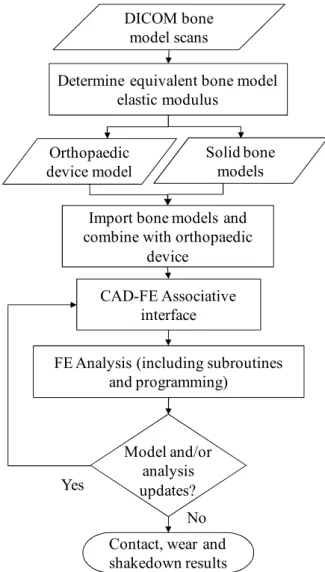
A. Computational and Numerical Processes
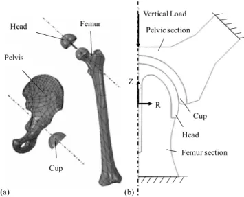
A technique has been developed to take patient bone scans and develop finite element (FE) contact models as described in Fig. 6. The acetabular cup and femoral head components were modelled using SolidWorks computer aided design. These orthopaedic models were combined with pelvis and femur models in an assembly. The associative interface between the computer aided design model and finite element model allowed for geometrical modifications to be made to the orthopaedic devices. The analysis was conducted using ABAQUS (Version 6.10-1) in combination with user defined subroutines and programming.
DICOM bone model scans
Import bone models and combine with orthopaedic
device
CAD-FE Associative interface Orthopaedic
device model
FE Analysis (including subroutines and programming)
Contact, wear and shakedown results Yes
No
Determine equivalent bone model elastic modulus
Solid bone models
Model and/or analysis updates?
Fig. 6. Bone scans to FE contact models
B. Finite Element Models
A number of finite element models were developed in this study. Common to all models, the hip resurfacing device was modelled nominally with a bearing diameter (df) of 50 mm
and diametral clearance (dc) of 80 µm [25]. For a simple
geometric comparison studies could be made, hip resurfacing components were backed and fully tied to rigid parts referred to as model 1 (shown in Fig. 7). Following on from model 1, the elasticity of attached bone was considered for the simulation of models 2-4. For all models, it is assumed that full contact and bonding is maintained between the top surface of the acetabular cup and acetablum and likewise between the bottom surface of the femoral head component and femur. Perfect sphericity of the cup and femoral head were also assumed. For initial conditions the cup and femoral head bearing centres coincided, and all model boundary conditions were subsequently applied within specified time steps.
Microseperation Fully rigid parts
Femoral head Acetabular cup Vertical Load
µ = 0.16 (coefficient of friction modelled between head and cup) y
x z
Fig. 7. Assembly of rigid backed components (model 1)
A number of vertical loading magnitudes were also considered in the study. A vertical load (Fy) of 3900 N was
applied based on the peak load expected during the walking cycle, however a stumbling load (Fs) of 11000 N and ISO
(International Organization of Standardization) load (FI) of
3000 N was also considered. High vertical loads such asFy
andFshave been highlighted to occur during patient walking
and stumbling [26]. For model 1 and model 2 the microseperation was modelled by translating the cup bearing centre in the lateral direction (i.e. along the anatomical lateral-medial axis) as used in experimental testing methods [23] and a finite element study of edge loading [27]. In addition to this method of modelling microseperaton, pure microseperation was also considered, which more closely replicates the theoretical model proposed by Mak, Besong, Jin and Fisher (Fig. 8), where is the cup inclination angle. The pure microseperation model will be based on a relocation of the femoral head centre both laterally and inferiorly where heal strike causes the head to relocate into the acetabular cup.
The coefficient of friction (µ) between the head and cup was modelled as 0.16 based on the friction factor of CoCrMo on CoCrMo (cobalt chromium molybdenum) in both bovine serum and synovial fluid [28]. Of all material combinations studied by Scholes, Unsworth and Goldsmith this was the largest friction factor value recorded. The coefficient of friction value modelled in finite element analysis has been shown to have a negligible effect on the contact pressure at low values of friction coefficients [25], however, as the surface friction coefficient increases during
the life of the component the subsurface stresses will also increase [29]. Therefore it has been considered in this study. Meshing techniques and element types were selected based on the geometry of the components and the type of problem being solved.
For contact modelling where plastic material models were considered [30], current literature has shown that the option for selecting a kinematic or isotropic hardening model would provide very similar results [31]. For all contact models normal hard contact behaviour was specified and the material properties have been obtained from literature as summarised in Table I [32], [33]. The stress-strain curves for ASTM F75 cobalt chrome has been provided in Fig. 9 [30]. For the application of shakedown theory, elastic-perfectly plastic material properties were considered. The material considered was ASTM F75 CoCrMo as cast material and the properties were adapted to consider an elastic-perfectly plastic material model.
x y
A C1
C2
C3
x y
S C1
C2
C3
0 x
y
x y
Fig. 8. Theoretical microseperation model [34]
For the bone model material properties an assessment was conducted to find an equivalent bone elastic modulus for the femur (BEF) and pelvis (BEP) as shown in table 1 to provide a
simplified material model for the contact analysis. This was obtained by comparing the model stiffness of a CT femur and pelvis bone scan loaded in all three directions (x,y,z) to obtainBEFandBEP. A sensitivity analysis was carried out on
a bone material model between elastic modulus values of 3GPa and 25 GPa applied to the pelvis and femur.
TABLE I
MATERIAL PROPERTIES
Material Elastic modulus (GPa)
Poisson s
ratio Density (kg/m
3)
CrCrMo 230 0.3 8270
BEF 12.3 0.3 1900
BEP 6.1 0.3 1900
The following assumptions can be made for the cobalt chrome to simplify the analysis: isotropic, homogenous and linear elastic. There is currently no study within literature which assumes cobalt chrome molybdenum to be a perfectly plastic material. However, for ductile materials an idealisation can be made which defines the material to have elastic-perfectly plastic materials properties.
approach, loading and boundary conditions from model 1 were considered in models 2-4.
0.00 0.05 0.10 0.15 0.20 0.25
0 200 400 600 800 1000 1200
S
tre
ss
(M
P
a)
Strain
Cast Cast (HIP) Wrought
Elastic-Perfectly Plastic
Fig. 9. Stress-Strain curves of ASTM F75 Cobalt Chrome
Vertical Load
Pelvic section
Femur section
Femoral head y
x z
Acetabular cup
Fig. 10. Segmented hip joint model (model 2)
A full hip finite element model (Fig. 11a) has been developed to provide validation for using a segmented model. This geometrically matches that of the segmented model (model 2) for ease of comparison, however the segmented model only consists of a section of the femur and pelvic bones. Although there are a number of image processing tools available to process bone scans, carrying out the finite element discritisation within the finite element analysis package meant that many of the advanced pre-processing tools within this environment could be utilized. A 2D axis symmetric model (Fig 11b) was developed following inspiration from the modelling techniques used by Udofia, Yew and Jin [25] as a model to conduct a cyclic shakedown analysis and assess the subsurface stresses under different vertical loading conditions.
Standard ISO loading (Fig. 12) and angular displacement (Fig. 13) data was used where flexion to extension and inward to outward rotation was applied within the wear model. This ensures that an accurate sliding distance is modelled which according to the Archard formulation is directly proportional to linear wear depth.
By considering the kinematics of the hip joint, it is understood that microseperation leads to edge loading during normal walking gait, and it is claimed that microseperation occurs during the swing phase of gait [36], [37]. The swing phase occurs between 60% to 100% of the gait cycle where the ball and cup fully relocate during heel
strike, it is at this stage that edge loading could occur. As the frequency of the walking cycle ranges from 0.4-2.2 Hz [38], it is also expected that edge loading could occur over a time period of 0.5s.
Cup Head
Pelvis
Femur
Femur section Pelvic section
Head Cup Vertical Load
R Z
Fig. 11. (a) full hip joint model (model 3) and (b) 2D Axis-symmetric model (model 4)
0 20 40 60 80 100
0.0 0.5 1.0 1.5 2.0 2.5 3.0 3.5
Fo
rc
e
(N)
Percentage time of cycle (%)
Fig. 12. Representation of ISO Gait Loading
To assess the effect of anteversion of the cup the model was modified to include a 15 anteversion. The maximum and minimum amount of anteversion to avoid increased levels of metal ions released into the body has been studied within literature [39] and the amount of anteversion applied in this study has been selected based on the outcomes and conclusions of the current literature.
The strategy of opting for a maximum vertical load of 3900 N and 11000 N to obtain realistic loading conditions was based on previously conducted vivo testing. The gait cycle loading and rotations for the wear simulations matched those applied during ISO experimental simulator testing. Therefore, the peak vertical load of 3000 N occurred at 10% and 50% of the walking cycle. Both flexion-extension and inward-outward rotation of the hip joint were modelled, when mechanical wear simulations were conducted using the segmented hip model.
0 20 40 60 80 100 -20
-10 0 10 20 30
Angul
ar Di
spl
ac
em
ent
(de
g)
Percentage of cycle time (%) Angle of flexion (+) or extension (-) ° ± 3 ° Angle of adduction (+) or abduction (-) ° ± 3 ° Angle of inward (+) or outward (-) ° ± 3 °
Fig. 13. Representation of ISO hip joint angular displacements
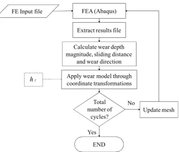
C. Wear Increment Methodology Development
Contact analysis forms a considerable part of simulating the mechanical wear of these devices. Two wear simulation strategies and methodologies were developed. The most commonly used method for ablating the mesh following wear depth calculation is through the use of user defined subroutines in combination with finite element techniques. This provides mesh control during the adaptive meshing procedure. In this study, the approach was developed further to calculate the linear wear at the end of each analysis increment, and the finite element mesh to be updated at the end of every increment. Secondly, a method of recording and saving the contact sliding distance during the analysis increments has also been developed along with the finite element analysis to determine the contact pressures. It is assumed that the wear coefficient obtained experimentally, will cover the complex wear mechanisms occurring during the wear process. The process describing the numerical wear process with the finite element method is described in Fig. 14 where is the finite element height,hjis the linear
wear depth andsis the sliding distance.
FE Input file FEA (Abaqus)
Read Interface Results
Apply wear model Calculate wear depth Determine wear direction
s smax
END
Wear depth Remeshing
No
Yes
No
Yes j
j
j h h
h 1
Fig. 14. Numerical wear simulations with the finite element method
FE Input file FEA (Abaqus)
Extract results file
Calculate wear depth magnitude, sliding distance
and wear direction
Apply wear model through coordinate transformations
END
No
Yes
T
h
Update mesh Total
number of cycles?
Fig. 15. Updated wear simulation method
The alternative method to this is using an interface which extracts data from the finite element analysis results. The data is then used to conduct sliding distance magnitude and cyclic wear depth calculations. At predefined cyclic intervals the mesh is then updated without the need to use an adaptive meshing algorithm. This method provides further analysis flexibility and process checking (Fig. 15).
For the proposed mechanical wear simulations and number of cycles the total wear depth is calculated for each node on the bearing surface as shown in (6). WherehIis the
total wear depth calculated over the total number of increments n for the analysis at each node of the bearing surface. The total volumetric wear over the testing period is given by hT (7), where k is the total number of cycle
increments before the mesh geometry is updated. The dimensional wear coefficient values have been obtained from literature [40].
ni
i i i I
kp
s
s
h
1
1
)
(
(6)
k
i I T h
h
1
(7)
D. Theoretical Contact and Microseperation Models The finite element model was validated against theoretical calculations under centred/normal loading conditions. These calculations were based on Hertz contact theory, which are shown in (8) and (9) [25] to calculate the contact radius (cr)
and maximum contact stress (po), where R, andE are the
effective radius, Poisson s ratio and modulus of elasticity respectively.
3
2
2 1 3 [
E R F
c I
r
(8)
2 2
3
b F
p I
o
(9)
Jin, and Fisher (10), wherecis the bearing radial clearance. [34] This model developed by the authors has been used as a basis for including microseperation within the computational analysis. The relocation due to heal strike was modelled by considering an initial dislocation of the femoral component and femur from the centre position.
c
rc
tan 1
1 (10)
IV. RESULTS
A. Model 1: Rigid Backed Model
Based on the walking gait peak vertical load of 3900 N the maximum contact pressure was 101 MPa without the inclusion of microseperation. The contact pressure increased to a maximum of 1284 MPa (Fig. 16) along with 675 MPa von Mises stress when 250 m of lateral displacement was applied in combination with the peak load as shown above the rim of the acetabular cup. By considering a lateral reaction force of 500N (in line with experimental simulator test methods) without any vertical load led to a maximum contact pressure of 564 MPa, von Mises stress of 456 MPa and maximum principal stress of 431 MPa.
Fig. 16. Rigid backed edge loading contact pressure distribution
The simulation conducted on this model considered one cycle of edge loading, however edge loading could occur in a cyclic manner. When the edge load was removed (i.e. contact removed) the plastic strain was predicted to be less than 0.03%. Through the assessments of the subsurface stresses in the edge loaded region it was found that the maximum residual stress occurred at the subsurface (Fig. 17). This subsurface strain profile was obtained through a combination of a peak load and microseperation following one loading cycle.
Fig. 17. Edge loaded subsurface strain location
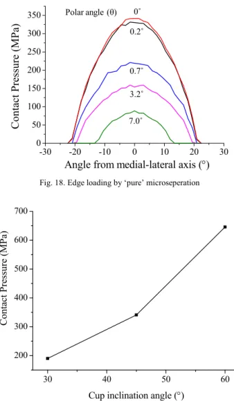
Through the assessment of edge loading due to pure microseperation using an explicit solver, the contact again was predicted to be initially above the rim of acetabular cup.
A symmetrical profile occurred about the centre of contact and the magnitude decreased as the azimuthal angle increased from the centre of contact. The contact radius was as large as 20 from the centre of contact. The maximum contact distribution did not occur on but above the rim radius of the cup. The contact pressure magnitude decreased as the polar angle increased where contact was observed below 7 (Fig. 18).
-30 -20 -10 0 10 20 30
0 50 100 150 200 250 300 350
C
o
n
ta
ct
Pr
essu
re
(
M
Pa
)
Angle from medial-lateral axis ()
0 0.17 0.73 3.2 6.95
Polar angle ( )
0.2
0.7
3.2
7.0 0
Fig. 18. Edge loading by pure microseperation
30 40 50 60
200 300 400 500 600 700
C
ont
ac
t Pre
ssure
(MPa
)
Cup inclination angle ()
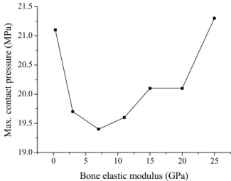
Fig. 19. Variation of contact pressure against cup inclination angle
By taking advantage of the customisable rigid backed model and through an efficient parametric study, the affect of cup inclination angle under pure microseperation conditions was observed (Fig. 19). The maximum contact pressure increased as the cup inclination angle increased from 30 to 60 . This range of cup inclination angle was considered to be sufficient to cover the variations between patients following implantation of the bearing devices.
B. Model 2-3: Segmented and Full Hip Model
For model 2, a 250 µm translation in the lateral direction led to an edge loading reaction force of 907 N. Based on the walking gait peak vertical load of 3900N the maximum contact pressure was 18 MPa without consideration of microseperation (Fig. 20).
As shown on the edge of the acetabular cup, the contact pressure (Fig. 21) and von Mises stress increased to a
maximum of 142 MPa and 141 MPa respectively when microseperation conditions were applied in combination with the peak load. When modelling an ISO gait loading profile in combination with a lateral sliding edge load the contact pressure profile was observed to be elliptical with the maximum contact pressure of 85 MPa occurring in the centre of contact.
By comparing the maximum stresses and stress distributions between model 1 and model 2-3 the effects of modelling strategy were observed. The contact patch for edge loaded acetabular cups and femoral heads were noted to be elliptical (with a high b/a ratio) compared with a circular contact area for centrally loaded cups and heads. The total contact area for centrally loaded contact and edge loading contact has been provided in Fig. 22. The highlighted pointsNIand Npare the contact area under ISO
and peak loading conditions without microseperation, howeverMIandMpare the contact area under ISO and peak
loading conditions with microseperation. Normal contact conditions occurred between t = 0 s tot = 1.0 s where no microseperation was applied. From t = 1.0 s to t = 2.0 s lateral microseperation conditions was included within the time step, where full edge loading condition occurred att= 2.0 s. The initial contact area at t = 0 s was caused by initial displacement control between the femoral head and acetabular cup. The ISO loading profile was observed by the variation of contact area over the analysis time step. A different contact area profile was obtained by applying a peak load in combination of the lateral sliding of the femoral head component.
The results obtained from the full hip model (model 3), showed maximum contact pressure under normal loading conditions to be 17 MPa, where a peak load Fywas applied
in the vertical direction. The sensitivity analysis of bone material elasticity modulus on the maximum contact pressure is shown in Fig. 23 where the same elastic modulus values were applied to both the cup and head, i.e. if an elasticity modulus of 20 GPa was applied to the femur material model, then 20 GPa was also applied to the pelvic model.
10 20 30 40 50 60
0 2 4 6 8 10 12 14 16 18 C ont ac t P re ss ur e ( M P a)
Polar angle ()
90.0 74.6 103.9 azimuthal angle ()
Fig. 20. Contact pressure distribution under normal loading (model 2)
-60 -40 -20 0 20 40 60
0 20 40 60 80 100 120 140 160 C ont ac t Pre ssure (MPa )
Azimuthal angle ()
4.2 9.8 15.2
-60 -40 -20 0 20 40 60
0 20 40 60 80 100 120 140 160
C
o
n
ta
ct
Pr
essu
re
(
M
Pa
)
Azimuthal angle (
)
4.2 9.8 15.2
-60 -40 -20 0 20 40 60
0 20 40 60 80 100 120 140 160
C
o
n
ta
ct
Pr
essu
re
(
M
Pa
)
Azimuthal angle (
)
4.2 9.8 15.2
-60 -40 -20 0 20 40 60
0 20 40 60 80 100 120 140 160
C
o
n
ta
ct
Pr
essu
re
(
M
Pa
)
Azimuthal angle (
)
4.2 9.8 15.2 Polar angle ( )
Fig. 21. Contact pressure distribution of edge loading
By including the affect of anteversion, the segmented hip joint assembly was modified with a cup anteversion angle of 15 . The maximum contact press ure again occurred in the region where the cup was backed by a stiffer region of the pelvis when lateral sliding was applied in combination with a peak load.
Normal contact conditions
Transition from normal to edge loading
NI
NP
MP
MI
0.0 0.5 1.0 1.5 2.0
0 40 80 120 160 200 240 280 320 C ont ac t A re a ( m m 2 ) Time (s) Peak Loading ISO Loading
Fig. 22. Total contact area between the femoral head and acetabular cup
0 5 10 15 20 25
19.0 19.5 20.0 20.5 21.0 21.5 M ax. c ont ac t pr es sur e ( M P a)
Bone elastic modulus (GPa)
The mechanical wear prediction for the volumetric material loss due to mechanical wear of femoral head under flexion to extension and internal to external rotation and ISO gait loading conditions was 82 mm3/mc (per million cycles), this was based on the first million cycles of loading. This was the volumetric wear loss for the femoral head components.
C. Shakedown Assessment (Models 1,2 and 4)
Based on shakedown maps for line and circular contact [17], [18] and a friction coefficient of 0.16 the component remains in an elastic state under contact loading as long as the load intensityPo/kdoes not exceed 3 (Fig. 24), wherePo
and kare the maximum contact pressure and material shear yield strength respectively. The value of k was calculated from the definition of this value in literature [18]. Based on theoretical shakedown maps and the maximum contact pressure observed from the analysis, the load intensity of the hip resurfacing devicesPo/kwas predicted to lie within the
elastic region of the shakedown map and not located in the elastic shakedown regions of the shakedown maps.
L
o
a
d
in
te
n
si
ty
Po
/k
Coefficient of frictionµ 1
0 2 3 4
5
0.1 0.2 0.3 0.4 0.5 Elastic region
Elastic-perfectly plastic shakedown limit Elastic shakedown region
Figure 24. Shakedown map representation for line contact [17]
0 2x10⁻⁵
4x10⁻⁵ 6x10⁻⁵
0 2 4 6 8 10 12 14 16
St
re
ss (MPa
)
Strain
Fig. 25. 2D-Axis symmetric cyclic stress-strain curve during normal loading
TABLE II
MAXIMUM VONMISES STRESS UNDER VERTICAL LOADS
Load Cup (max. stress MPa) Head (max. stress MPa)
FI 34 15
Fy 45 21
Fs 125 66
a
a107 MPa predicted at the base of the femoral head stem
FI
Acetabular cup
Fy
Fs
Femoral head Load
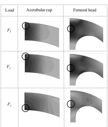
Figure 26. von Mises stress distributions under vertical loads
By conducting the 2D axis-symmetric cyclic analysis using model 4, the stress-strain curve (Fig. 25) predicts the hip resurfacing device material to remain within the elastic region under normal loading conditions. The loading curve shows the first 6 loading cycles.
The subsurface von Mises stress can be observed on the subsurface of both the acetabular cup and femoral head components (Fig. 26) under FI,Fy and Fs vertical loading
conditions. The locations of maximum von Mises stresses have been circled and as shown the maximum von Mises stresses occurred below the surface of contact, it was only when a stumbling loadFswas applied that the maximum von
Mises stress occurred at the base of the head component (Table II).
V. DISCUSSION
head. For all three dimensional models, the plastic strains and stress were predicted to occur above the rim radius of the cup which matches the inspections from patient retrievals and bearing components following experimental simulator testing with microseperation. The corresponding contact profile on the femoral head component was also dependent upon the anteversion angle of the implanted cup. Due to the geometric nature of the femoral head the anteversion of the cup would not have any effect upon the contact pressure profile and magnitude on the acetabular cup, therefore the effect of anteversion was only assessed on the femoral head. The contact pressures were also found to be insensitive to bone elastic modulus, even though a large range ofEvalues were modelled as a form of methodology verification.
The magnitude of stresses and contact pressures observed may appear large for model 1 however, the rigidity of backing components increased the results by at least a factor of 5 over the results obtained using models 2-4. These high levels of contact pressure and stress were also been observed by Mak et al. [27]. The maximum stress and therefore plastic strain was observed below the surface of the material as predicted by Hertz theory for surfaces in contact with a coefficient less than 0.3. For model 1, the total contact area under edge loading conditions was at least 2.7 times less than under central/normal contact conditions. This was an important finding as the contact patch dimensions directly affects the linear wear as does the contact pressure according to the Archard wear model used to study wear of the bearing surfaces.
When considering both cyclic gait loading and high stumbling loads no plasticity was observed in models 2-4, therefore, in reality it was predicted that material plasticity would not occur under normal, edge loading or extreme stumbling load conditions. In addition to assessing the plasticity and fracture, fatigue assessments are an important consideration for any cyclically loaded component, through this study it was deemed that fatigue strength along with fracture toughness of Cobalt Chromium are significantly larger than bone. The fracture toughness of cobalt-chromium-molybdenum (CoCrMo) could be up to 50 times greater than for bone [41]. This high fracture toughness would much sooner cause femoral neck fracture [42], [43] before fracture or fatigue failure of the metal-on-metal device.
It was possible to assess the reaction forces in the edge loaded regions to determine the contact stress results at specific lateral sliding magnitudes. The microseperation distance of 250 µm was equivalent to a force greater than that considered in experimental simulator studies which is typically 200 N to 500 N in magnitude. These observations also explain the high values of edge loading contact pressure observed in model 1. Although the effect of bone geometry on the edge loading contact pressure distribution was observed when a combination of lateral sliding and a peak load was modelled, the contact pressured reduced while the edge load was applied during the swing phase load of the ISO gait loading cycle.
Based on the maximum contact pressure, calculated value of kand therefore a low value of load intensity, suggested that the component under central and edge loading
conditions would remain within the elastic region of a contact shakedown map, which is a safe region for the component to be operating in. Therefore, in terms of the hip resurfacing device s response to loading, elastic shakedown, plastic shakedown or ratcheting behaviour is unlikely to be observed, during normal contact conditions, edge loading or stumbling load conditions.
By assessing affect of cup inclination angle under pure microseperation and relocation, the increases in contact pressure above a 45 cup inclination agrees with the clinical observations of increased wear rates from patients with implanted hip resurfacing devices [44], however, it should be noted that this was conducted without any anteversion of the acetabular cup.
For the mechanical wear simulations a cyclic ISO loading profile was applied in combination with hip rotations. Assumptions were made between the numerical and experimental strategies to simplify the model. These simulations provided comparative results against the findings from experimental simulator studies. The dimensional wear coefficients from current literature provided material and application specific values to be applied to the Archard wear model.
VI. CONCLUSION
A combination of computational, numerical and theoretical techniques have been used and developed, which formed the basis of studying the contact mechanics, wear and shakedown of hip resurfacing device. The finite element method was used to build contact models, develop numerical mechanical wear techniques from previous studies and assess the application of shakedown theory to normal and edge loaded hip joint resurfacing devices under different loading conditions. The severity of edge loading contact was observed along with the significance and sensitivity of results based on the bone backed anatomical geometry and assembly. Based on the assumptions made in this study and the modelling conditions to simulate normal and edge loading for hip joint resurfacing devices, predictions showed that although cyclic loading is present during the operation of the hip resurfacing devices, elastic shakedown, plastic shakedown or rachetting is not predicted to occur. The resurfacing device material is predicted to remain operating within the elastic region. It should be noted that this conclusion is drawn without the direct assessment of asperity shakedown, which will be considered in future studies.
The scope for studying the contact mechanics and wear of hip resurfacing devices within its designed applications of being implanted into patients is possible without the need for complex density based material models. During this study it was found that an equivalent bone modulus can be used without the need for refinement as the affect on producing highly varied contact pressures was negligible.
microseperation model which provides further explanation of the increasing wear rates as observed by in-vitrostudies and patient retrievals. Both microseperation simulation models showed an increase of contact stress by at least a factor of 2 over normal or centrally loaded hip resurfacing devices, depending on a number of factors including the anteversion of the acetabular cup and load magnitude. This level of contact stress increase compares closely to the level of wear rate increase from in-vitro experimental simulator studies which includes microseperation.
The Archard wear model in combination with the FE solver provided a basis for predicting the wear of the bearing surface. The methodological approach adopted in this study meant that numerical and process checks could be performed at every step to ensure that the developed simulations provided understandable results. Further work is required to reduce the total number of increments to update the finite element mesh more regularly, this will in turn allow for a contact pressure distribution which is more dependant upon the worn surface geometry. The wear simulations should also consider the variation in dimensional wear coefficient throughout the cyclic life of the bearing components.
In this study modelling verification, comparative solutions to other studies and theoretical models have been developed for centered contact conditions; however, further work is required to develop theoretical and computational models to more accurately simulate and assess the effects of real patient specific consequences of edge loading and microseperation on hip resurfacing devices. The kinematics of these conditions during human joint motion should be considered in more depth if simulations are to accurately model these problems. Overall, using a combination of techniques and theoretical models has shown to be beneficial in developing numerical analysis of hip resurfacing devices under specific conditions.
REFERENCES
[1] J. G. Bowsher, T. K. Donaldson, P. A. Williams, and I. C. Clarke, "Surface Damage After Multiple Dislocations of a 38-mm-Diameter, Metal-on-Metal Hip Prosthesis,"Journal of Arthroplasty, vol. 23, pp. 1090-1096, Oct 2008.
[2] W. L. Walter, G. M. Insley, W. K. Walter, and M. A. Tuke, "Edge loading in third generation alumina ceramic-on-ceramic bearings,"
Journal of Arthroplasty,vol. 19, pp. 402-413, Jun 2004.
[3] S. Williams, T. D. Stewart, E. Ingham, M. H. Stone, and J. Fisher, "Metal-on-metal bearing wear with different swing phase loads,"
Journal of Biomedical Materials Research Part B-Applied Biomaterials,vol. 70B, pp. 233-239, Aug 2004.
[4] M. Manaka, I. C. Clarke, K. Yamamoto, T. Shishido, A. Gustafson, and A. Imakiire, "Stripe wear rates in alumina THR - Comparison of microseparation simulator study with retrieved implants,"Journal of Biomedical Materials Research Part B-Applied Biomaterials,vol. 69B, pp. 149-157, May 2004.
[5] I. J. Leslie, S. Williams, G. Isaac, E. Ingham, and J. Fisher, "High Cup Angle and Microseparation Increase the Wear of Hip Surface Replacements," Clinical Orthopaedics and Related Research,vol. 467, pp. 2259-2265, 2009.
[6] R. A. Poggie, T. R. Turgeon, and R. D. Coutts, "Failure analysis of a ceramic bearing acetabular component,"Journal of Bone and Joint Surgery-American Volume,vol. 89A, pp. 367-375, Feb 2007. [7] M. Ali and K. Mao, "Modelling of hip resurfacing device contact
under central and edge loading conditions," Lecture Notes in Engineering and Computer Science: Proceedings of The World Congress on Engineering 2012, WCE 2012, 4-6 July, London, U.K. pp. 2054-2059, 2012.
[8] K. L. Johnson, Contact mechanics / K.L. Johnson. Cambridge : Cambridge University Press, 1985.
[9] J. E. Shigley,Mechanical engineering design / Joseph E. Shigley, Charles R. Mischke, 6th ed. ed. Boston :: McGraw Hill, 2001. [10] H. F. El'Sheikh, B. J. MacDonald, and M. S. J. Hashmi, "Finite
element simulation of the hip joint during stumbling: a comparison between static and dynamic loading," Journal of Materials Processing Technology,vol. 143-144, pp. 249-255, 2003.
[11] A. Z. Senalp, O. Kayabasi, and H. Kurtaran, "Static, dynamic and fatigue behavior of newly designed stem shapes for hip prosthesis using finite element analysis," Materials & Design, vol. 28, pp. 1577-1583, 2007.
[12] T. Tateiwa, I. C. Clarke, G. Pezzotti, L. Sedel, T. Kumakura, T. Shishido, et al., "Surface micro-analyses of long-term worn retrieved "Osteal (TM)" alumina ceramic total hip replacement,"Journal of Biomedical Materials Research Part B-Applied Biomaterials,vol. 83B, pp. 562-570, Nov 2007.
[13] S. Williams, A. Schepers, G. Isaac, C. Hardaker, E. Ingham, D. van der Jagt, et al., "The 2007 Otto Aufranc Award - Ceramic-on-metal hip arthroplasties - A comparative in vitro and in vivo study,"
Clinical Orthopaedics and Related Research,pp. 23-32, Dec 2007. [14] R. Pourzal, R. Theissmann, S. Williams, B. Gleising, J. Fisher, and
A. Fischer, "Subsurface changes of a MoM hip implant below different contact zones," Journal of the Mechanical Behavior of Biomedical Materials,vol. 2, pp. 186-191, Apr 2009.
[15] J. F. Archard, "Contact and Rubbing of Flat Surfaces,"Journal of Applied Physics,vol. 24, pp. 981-988, 1953.
[16] T. A. Maxian, T. D. Brown, D. R. Pedersen, and J. J. Callaghan, "A sliding-distance-coupled finite element formulation for polyethylene wear in total hip arthroplasty,"Journal of Biomechanics,vol. 29, pp. 687-692, 1996.
[17] J. A. Williams, "The influence of repeated loading, residual stresses and shakedown on the behaviour of tribological contacts,"Tribology International,vol. 38, pp. 786-797, 2005.
[18] A. R. S. Ponter, H. F. Chen, M. Ciavarella, and G. Specchia, "Shakedown analyses for rolling and sliding contact problems,"
International Journal of Solids and Structures,vol. 43, pp. 4201-4219, 2006.
[19] J. A. Williams, I. N. Dyson, and A. Kapoor, "Repeated loading, residual stresses, shakedown, and tribology,"Journal of Materials Research,vol. 14, pp. 1548-1559, Apr 1999.
[20] K. L. Johnson, "The application of shakedown principles in rolling and sliding contact,"Eur. J. Mech., A/Solids, vol. 11, pp. pp155-172, 1992.
[21] T. Shishido, I. C. Clarke, P. Williams, M. Boehler, T. Asano, H. Shoji, et al., "Clinical and simulator wear study of alumina ceramic THR to 17 years and beyond," Journal of Biomedical Materials Research Part B-Applied Biomaterials,vol. 67B, pp. 638-647, Oct 2003.
[22] P. J. Firkins, J. L. Tipper, E. Ingham, M. H. Stone, R. Farrar, and J. Fisher, "Influence of simulator kinematics on the wear of metal-on-metal hip prostheses,"Proceedings of the Institution of Mechanical Engineers Part H-Journal of Engineering in Medicine,vol. 215, pp. 119-121, 2001.
[23] T. Stewart, J. Tipper, R. Streicher, E. Ingham, and J. Fisher, "Long-term wear of HIPed alumina on alumina bearings for THR under microseparation conditions," Journal of Materials Science-Materials in Medicine,vol. 12, pp. 1053-1056, 2001.
[24] S. K. Wong, A. Kapoor, and J. A. Williams, "Shakedown limits on coated surfaces,"Thin Solid Films,vol. 292, pp. 156-163, 1997. [25] I. J. Udofia, A. Yew, and Z. M. Jin, "Contact mechanics analysis of
metal-on-metal hip resurfacing prostheses," Proceedings of the Institution of Mechanical Engineers Part H-Journal of Engineering in Medicine,vol. 218, pp. 293-305, 2004.
[26] G. Bergmann, F. Graichen, A. Rohlmann, A. Bender, B. Heinlein, G. N. Duda, et al., "Realistic loads for testing hip implants," Bio-Medical Materials and Engineering,vol. 20, pp. 65-75, 2010. [27] M. Mak, Z. Jin, J. Fisher, and T. D. Stewart, "Influence of
Acetabular Cup Rim Design on the Contact Stress During Edge Loading in Ceramic-on-Ceramic Hip Prostheses," The Journal of Arthroplasty,vol. 26, pp. 131-136, 2011.
[28] S. C. Scholes, A. Unsworth, and A. A. J. Goldsmith, "A frictional study of total hip joint replacements," Physics in Medicine and Biology,vol. 45, pp. 3721-3735, Dec 2000.
[30] Materials and Coatings for Medical Devices: Cardiovascular: ASM International, 2009.
[31] Y. Zait, V. Zolotarevsky, Y. Kligerman, and I. Etsion, "Multiple Normal Loading-Unloading Cycles of a Spherical Contact Under Stick Contact Condition,"Journal of Tribology-Transactions of the Asme,vol. 132, p. 7, Oct 2010.
[32] R. Hodgskinson and J. D. Currey, "Young modulus, density and material properties in cancellous bone over a large density range,"
Journal of Materials Science-Materials in Medicine, vol. 3, pp. 377-381, 1992.
[33] M. Dalstra, R. Huiskes, and L. Vanerning, "Development and validation of a 3-dimensional finite-element model of the pelvis bone,"Journal of Biomechanical Engineering-Transactions of the Asme,vol. 117, pp. 272-278, 1995.
[34] M. M. Mak, A. A. Besong, Z. M. Jin, and J. Fisher, "Effect of microseparation on contact mechanics in ceramic-on-ceramic hip joint replacements," Proceedings of the Institution of Mechanical Engineers Part H-Journal of Engineering in Medicine,vol. 216, pp. 403-408, 2002.
[35] D. G. Steele and C. A. Bramblett,The Anatomy and Biology of the Human Skeleton: Texas A&M University Press, 1988.
[36] A. V. Lombardi, T. H. Mallory, D. A. Dennis, R. D. Komistek, R. A. Fada, and E. J. Northcut, "An in vivo determination of total hip arthroplasty pistoning during activity,"Journal of Arthroplasty,vol. 15, pp. 702-709, Sep 2000.
[37] D. A. Dennis, R. D. Komistek, E. J. Northcut, J. A. Ochoa, and A. Ritchie, ""In vivo" determination of hip joint separation and the forces generated due to impact loading conditions," Journal of Biomechanics,vol. 34, pp. 623-629, 2001.
[38] S. Affatato, A. Spinelli, M. Zavalloni, C. Mazzega-Fabbro, and A. Viceconti, "Tribology and total hip joint replacement: Current concepts in mechanical simulation," Medical Engineering & Physics,vol. 30, pp. 1305-1317, Dec 2008.
[39] D. J. Langton, A. P. Sprowson, S. Jameson, T. J. Joyce, M. Reed, P. Partington, et al., "Blood metal ion concentrations post hip resurfacing arthroplasty: a comparison study of the articular surfacereplacement and Birmingham hip resurfacing devices,"
Journal of Bone & Joint Surgery, British Volume, vol. 92-B, pp. 390-390, 2010.
[40] F. Liu, I. Leslie, S. Williams, J. Fisher, and Z. Jin, "Development of computational wear simulation of metal-on-metal hip resurfacing replacements," Journal of Biomechanics, vol. 41, pp. 686-694, 2008.
[41] R. E. Smallman and R. J. Bishop, "Modern Physical Metallurgy and Materials Engineering - Science, Process, Applications (6th Edition)," ed: Elsevier, 1999.
[42] H. Sharma, B. Rana, C. Watson, A. Campbell, and B. Singh, "Femoral neck fractures complicating metal-on-metal resurfaced hips: a report of 2 cases," Journal of Orthopaedic Surgery 2005;13(1):69-72,2005.
[43] D. R. Marker, T. M. Seyler, R. H. Jinnah, R. E. Delanois, S. D. Ulrich, and M. A. Mont, "Femoral neck fractures after metal-on-metal total hip resurfacing," Journal of Arthroplasty, vol. 22, pp. 66-71, 2007.
![Fig. 3. Contact area for (a) circular contact (b) elliptical contact (c) theoretical edge loading contact [8]](https://thumb-eu.123doks.com/thumbv2/123dok_br/16295170.185672/2.892.74.431.504.991/contact-circular-contact-elliptical-contact-theoretical-loading-contact.webp)
![Fig. 4. Material response the cyclic loading from shakedown theory [17]](https://thumb-eu.123doks.com/thumbv2/123dok_br/16295170.185672/3.892.461.829.713.893/fig-material-response-cyclic-loading-shakedown-theory.webp)
![Fig. 8. Theoretical microseperation model [34]](https://thumb-eu.123doks.com/thumbv2/123dok_br/16295170.185672/5.892.461.819.430.595/fig-theoretical-microseperation-model.webp)