Breaking and Motility
Mark J. Dayel1*, Orkun Akin2, Mark Landeryou3, Viviana Risca4, Alex Mogilner5,6, R. Dyche Mullins2
1Miller Institute for Basic Research in Science, University of California Berkeley, Berkeley, California, United States of America,2Department of Cellular and Molecular Pharmacology, University of California San Francisco, San Francisco, California, United States of America,3Department of Mechanical Engineering, University College London, London, United Kingdom,4Biophysics Graduate Group, University of California Berkeley, Berkeley, California, United States of America,5Department of Mathematics, University of California Davis, Davis, California, United States of America,6Department of Neurobiology, Physiology, and Behavior, University of California Davis, Davis, California, United States of America
Abstract
Eukaryotic cells assemble viscoelastic networks of crosslinked actin filaments to control their shape, mechanical properties, and motility. One important class of actin network is nucleated by the Arp2/3 complex and drives both membrane protrusion at the leading edge of motile cells and intracellular motility of pathogens such asListeria monocytogenes. These networks can be reconstituted in vitro from purified components to drive the motility of spherical micron-sized beads. An Elastic Gel model has been successful in explaining how these networks break symmetry, but how they produce directed motile force has been less clear. We have combined numerical simulations with in vitro experiments to reconstitute the behavior of these motile actin networks in silico using an Accumulative Particle-Spring (APS) model that builds on the Elastic Gel model, and demonstrates simple intuitive mechanisms for both symmetry breaking and sustained motility. The APS model explains observed transitions between smooth and pulsatile motion as well as subtle variations in network architecture caused by differences in geometry and conditions. Our findings also explain sideways symmetry breaking and motility of elongated beads, and show that elastic recoil, though important for symmetry breaking and pulsatile motion, is not necessary for smooth directional motility. The APS model demonstrates how a small number of viscoelastic network parameters and construction rules suffice to recapture the complex behavior of motile actin networks. The fact that the model not only mirrors our in vitro observations, but also makes novel predictions that we confirm by experiment, suggests that the model captures much of the essence of actin-based motility in this system.
Citation:Dayel MJ, Akin O, Landeryou M, Risca V, Mogilner A, et al. (2009) In Silico Reconstitution of Actin-Based Symmetry Breaking and Motility. PLoS Biol 7(9): e1000201. doi:10.1371/journal.pbio.1000201
Academic Editor:Thomas Pollard, Yale University, United States of America
ReceivedOctober 28, 2008;AcceptedAugust 12, 2009;PublishedSeptember 22, 2009
Copyright:ß2009 Dayel et al. This is an open-access article distributed under the terms of the Creative Commons Attribution License, which permits unrestricted use, distribution, and reproduction in any medium, provided the original author and source are credited.
Funding:This work is supported by the Miller Institute for Basic Research in Science, Berkeley (http://millerinstitute.berkeley.edu/), the UCSF/UCB Nanomedicine Development Center (http://nanomedcenter.org/centers/cpl), National Institutes of Health grants RO1 GM61010 and U54 GM64346 (http://www.nih.gov/), a National Science Foundation grant DMS-0315782 (http://www.nsf.gov/), a University of California Systemwide Biotechnology Research and Education Program GREAT Training grant 2007-14 (http://ucbrep.ucdavis.edu/), a Paul and Daisy Soros Fellowship for New Americans (http://www.pdsoros.org/), and the Sandler Family Supporting Foundation. The funders had no role in study design, data collection and analysis, decision to publish, or preparation of the manuscript.
Competing Interests:The authors have declared that no competing interests exist.
Abbreviations:APS, Accumulative Particle-Spring. * E-mail: [email protected]
Introduction
The directed assembly of actin networks drives the motility of most eukaryotic cells [1]. Specialized cellular factors assemble actin into different network types, each with a unique architecture and cellular function [2]. One of the most well-studied actin assembly factors is the Arp2/3 complex, a seven-subunit protein complex that nucleates new filaments from the sides of pre-existing filaments to create entangled, dendritic filament arrays [3,4]. These arrays behave like viscoelastic gels with an elasticity that depends on the degree of branching, and which break or rip under relatively low stress [5].
In vivo, dendritic networks built by Arp2/3 complex form the lamellipod that drives the movement of eukaryotic cells [3,6] as well as the ‘‘comet tails’’ whose assembly drives the intracellular movement of endosomes [7,8] and intracellular pathogens [9] such as Vaccinia virus [10] andListeria[11]. Construction of these motile networks in vivo requires a set of highly conserved accessory
proteins, including capping protein, cofilin, and profilin, that function together with the Arp2/3 complex in a simple biochemical cycle converting monomeric actin into crosslinked polymer and back again [6,12]. Motile, dendritic actin networks can also be constructed in vitro by recombining purified components of the actin assembly cycle [13–16]. These reconsti-tuted actin networks have become a powerful tool for studying how individual protein–protein interactions control the large-scale behaviors of cytoskeletal systems.
biochemically symmetric bead can first break symmetry then maintain asymmetry to produce directed smooth or pulsatile motion.
Spatially localized nucleation of actin filaments combined with global inhibition of filament elongation by capping protein restricts filament growth to a well-defined zone, e.g., theListerium surface [21], lamellipodial plasma membrane [22], etc. On the spatial scale of filaments, a Brownian ratchet mechanism has been proposed [23,24] to explain how actin polymerization uses the energy of ATP hydrolysis to rectify Brownian fluctuations, exerting force at the surface, as new actin monomers, as new actin monomers add onto existing filaments and extend the network. Although the specific details may vary [25–27], spatially localized network extension fueled by ATP hydrolysis is the basis of all polymerization-driven motility models.
Several theoretical frameworks have been proposed to explain actin-based symmetry breaking and bead motility (reviewed in [28]). Some are based on filament-scale descriptions of actin assembly and crosslinking [29,30], while others take a more coarse-grained approach based on the bulk mechanical properties of crosslinked polymer networks [17,19,20,31–34]. One such coarse-grained model is the Elastic Gel model [19,31], which provides an intuitive explanation for symmetry breaking. In this model, symmetry breaking occurs when new actin network, continuously deposited at the surface of the bead, displaces older portions of the network radially outward. Expansion of the older network stretches it like the surface of an inflating balloon until, at a critical threshold, circumferential stress causes a rupture in the network (either by melting [33] or cracking [35] the shell) and breaks the symmetry of the system. This mechanism fits the experimental observations of symmetry breaking [16,19] better than mechanisms inferred from filament-based descriptions of the network [30]. Pulsatile motion has been suggested to result from an unstable balance between the pushing forces and the drag from attached filaments [20].
Explaining the smooth directional motility of symmetrically coated beads has proved more challenging. One attempt, the Soap-Squeezing model [31], is an extension of the Elastic Gel model that offers an explanation of propulsive force. In this model, surface-associated polymerization stretches older network out-wards orthogonal to the direction of motion, storing energy, which it releases by contracting orthogonally, squeezing the bead forward
like a hand squeezing a wet bar of soap. However, photobleaching data showing the movement of the network as it leaves the bead demonstrate that orthogonal squeezing does not occur [17], and whereas treating the network as an incompressible fluid flowing from the bead surface can explain the observed motion [17], this violates the elastic nature of the gel required to explain the initial symmetry breaking. How, then, does sustained motility occur?
In this paper, we examine the essence of actin-based bead motility by reconstituting it in silico from the network’s fundamental viscoelastic properties. Just as reconstituting actin-based motility in vitro from a minimal set of purified protein components demonstrates their necessity and can show how they contribute to the large-scale behavior, reconstituting actin-based motility in silico allows us to demonstrate the necessity and specific contributions of a minimal set of higher-level network properties (e.g., elasticity, crosslinking, etc.), and demonstrate the mecha-nisms of motility on a mesoscopic scale. To do this, we use a framework we call the Accumulative Particle-Spring model (APS model) in which the viscoelastic actin network is represented simply as a set of particles, subject to viscous drag and coupled by springs that break when strained beyond a certain limit. New Particle-Spring network is created at the bead surface, just as the in vitro actin network polymerizes at the bead surface [16], and we find that this simple system is sufficient to reproduce a range of the behaviors of actin networks, including symmetry breaking and motility.
Our simulations enable us to explore the feasibility of hypothesized mechanisms of force and movement generation, using Ockham’s razor to determine the essence of the behavior by exploring the minimal requirements to produce the observed results. We validate the model by checking the results and predictions of the simulations with in vitro experiments in which we reconstitute symmetry breaking and motility from purified proteins. To the extent that the model is valid, we are able to make explanatory claims for the mechanisms involved in symmetry breaking and motility, determining 1) the stress and strain distributions in a growing symmetric actin shell and in a comet-like tail, 2) where the symmetry break is initiated (outer or inner surface of the actin shell), 3) the 3-D structure and dynamics of the break, 4) what determines the transition from smooth to pulsatile motility, and 5) how symmetry breaking occurs for nonspherical objects.
Results
Viscoelastic Forces Drive Bead Motility
To perform our in vitro bead motility experiments, we evenly coated 5-mm diameter beads with ActA and added them to motility mix (see Materials and Methods). ActA activates Arp2/3 to nucleate an actin network that grows in a tightly localized zone at the bead surface, breaks symmetry, and propels the bead on an actin comet tail (Figure 1A–1D and Video S1).
To find out how well bead motility can be explained simply by the viscoelastic properties of the network, we created a computational model that simulates the behavior of a generic viscoelastic network deposited stochastically at the surface of a bead. The model starts att= 0 with no network, then nucleates nodes at a constant rate and with an even distribution across the bead surface, crosslinking new nodes to their neighbors with links that behave as simple Hookean springs that break if extended too far (Figures S1 and S2). See Materials and Methods and Section S1 of the supporting text (Protocol S1) for full details of the model, and Tables S1 and S2 for the experimental bases for the model assumptions. We tuned the model parameters (spring constant, Author Summary
crosslinking probability, etc.) to produce qualitatively similar observations to the in vitro system (see Model Robustness, Section S3 of the supporting text (Protocol S1) for the effects of varying each parameter. Table S3 lists the corresponding names in the code for simulation parameters mentioned in the main text). This simple model exhibits both symmetry breaking and motility behavior that reproduces the sequence of events seen in vitro (Figure 1E–1H, Video S2).
Our experimental observations and our simulations share several features. As the shell grows, it becomes denser near the surface of the bead. When the thickness of the shell reaches approximately the radius of the bead, a clear crack develops, and the bead exits the shell, then the shell opens, crescent-like, and motility proceeds, leaving a low-density and somewhat irregular comet-like tail behind the bead. Figure 1I–1L show the underlying 3-D nature of the simulated network, with the network links colored by tensile stress (Videos S3 and S4).
Geometry of Symmetry Breaking
Although the simulations share many of the features of the experiments, we noticed that the shell shows a close to perfect arc for the experimental conditions in Figure 1, but the simulations robustly show a more V-like shape with a dent in the center of the inner high-density region of the shell (compare Figure 1C and 1D with 1G and 1H). This implies either a failure of the simulation to capture an essential behavior of the network, or a condition of the in vitro system that we did not include in the simulations.
To determine the cause of the dent, we examined the 3-D mechanics of symmetry breaking in our simulations. Figure 2A
and 2B show 3-D top and side views of a representative simulated shell after the bead has moved away from the shell, demonstrating that even though the bead is unconstrained in three dimensions, the symmetry break and shell opening occur along only one axis. A rip in the outer shell often accompanies the dent, as seen in Figure 2A (arrow) and the corresponding 2-D projection view shown in Figure 2C. To understand why symmetry breaking occurs within one plane, we looked at how the shell cracks. Figure 2-D shows an earlier 3-D view of the same simulation, just as the crack completely fractures the shell; isosurfaces show the densest region of the network in green to highlight the shape of the shell, and the extent of the lower-density actin network (semitransparent). The symmetry-breaking crack is a straight line, as opposed to either lightning-like fracture(s) along the weakest regions of the network, or a circular hole opening to allow the bead to escape. The consequence of this straight-line break is that the 3-D stresses in the network are relieved in a 2-D manner— essentially splitting the 3-D spherical shell into two hemispheres that open apart from one another like a clamshell, causing large stresses at the hinge. When this 3-D geometry is viewed from above, the hinge appears as a dent, seen in Figure 2A and 2C. The crack that opens the two hemispheres often continues all the way around the outer network, resulting in the rip in the outer shell that accompanies the dent. For only one rip to occur, as soon as a crack begins, circumferential tension must relax quickly around the bead before a second crack begins. We can reduce this relaxation around the bead by increasing the strength of attachments with the nucleator (Figure S16), which prevents the network moving relative to the bead and makes the second crack progressively more prominent.
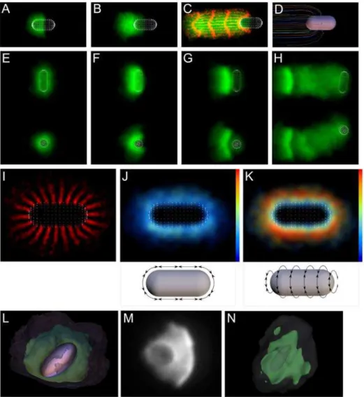
Figure 1. Simulations qualitatively mimic in vitro symmetry breaking and bead motility. (A–D) Time series of in vitro symmetry breaking and motility for beads uniformly coated with ActA (see Video S1). (E–H) Time series of a computer simulation of symmetry breaking and motility (2-D projections convolved with Gaussian, projection plane chosen parallel to shell opening; see Video S2). (I–L) 3-D view of simulation showing links colored by tensile stress (see Video S3; color bar range represents zero [blue] to breakage stress [red]). A–D correspond to 70s, 106s, 175s and 344s. E–H and I–J correspond to frames 70, 134, 185 and 330 of the simulation (see Figure 3 for detailed kinetics).
For the experimental conditions in Figure 1, we had intentionally confined the bead closely between a slide and coverslip to prevent it moving out of focus while we took data. Having seen how the crack propagates around the bead in the
simulations, we hypothesized that the lack of a dent seen in the experiments might be a result of this constraint on the network preventing the crack propagating to the rear of the bead. To test this, we ran the same simulation while constraining the network
Figure 2. The 3-D geometry of symmetry breaking.(A and B) Top and side views of simulated network shortly after symmetry breaking showing that symmetry breaking is in one axis only. (C) 2-D projection of unconstrained simulation after symmetry breaking shows dent in the center of the shell. (D) 3-D isosurface representation of network and bead during symmetry breaking shows linear crack. (E and F) Same as (C and D), but network is constrained inz-direction between two parallel planes to mimic experimental conditions (note lesser dent in shell). (G–J) Projections and 3-D reconstructions of experimental data after symmetry breaking. (G and H) show a 5-mm bead with 15.5-mm spacers, (I and J) a 5-mm bead with 5.1-mm spacers. Arrows in (A–H) indicate rip in outer shell. See Figures S4, S5, and S6 for interactive 3D views.
between two planes (we also excluded nucleation from the very top and bottom 10% of the bead to prevent artifacts caused by this material having nowhere to go). Figure 2E and 2F correspond to 2C and 2D, but for this constrained shell (interactive 3-D representations are included in Figure S4). The constraint creates a toroidal shell that also breaks in a straight-line crack, but unlike the breaking of the spherical shell, the broken toroidal shell relaxes into a much more perfect arc, with the dent much reduced and the shell more closely resembling those seen in the experiments.
If our simulations are a valid model for the behavior of the actin network, they predict that if we were to perform the symmetry-breaking experiment in an unconstrained 3-D volume in vitro, it would produce a clamshell break with a dent in the shell opposite the break site as we see in the simulations. To test this, we performed the in vitro experiment using 5-mm diameter ActA-coated beads while controlling the headspace of the reaction with glass spacer beads of either 5.1-mm diameter for the constrained condition or 15.5mm for the unconstrained condition. Because the 3-D shell structure is hard to interpret from a single 2-D microscope image, we reconstructed the 3-D shells from confocal z-stacks. We fixed the reaction after symmetry breaking (see Materials and Methods) to prevent movement while the z-stack was acquired; so for experiments, we are only able to capture the 3-D geometry at one time point after symmetry breaking has occurred, in contrast to having every time point in the simulations. Figure 2G and 2H show an example of a 2-D projection and 3-D reconstruction of a confocal stack of an unconstrained bead, confirming the distinctive bilobed structure, and V-shaped shell with central dent. Figure 2I and 2J similarly show the constrained condition with the near-perfect arc. (Beads tend to settle by gravity so that the tail and wide axis of shell are parallel to the coverslip, with shell cracks in the z-direction.) Figures S5 and S6 contain further examples of 2-D projections and 3-D reconstructions of symmetry breaking. Shell geometry for constrained beads was extremely consistent, always showing the near-perfect arc. Unconstrained beads showed less regularity, but always showed shells with shapes consistent with linear cracks; on one occasion, we observed a shell with a three-way opening (Figure S6B).
Shell Deformations during Symmetry Breaking
To confirm that the mechanics of symmetry breaking in our simulations reflect those seen in vitro, we tracked the deformations of the shell during in vitro symmetry breaking using fluorescent speckle microscopy (Figure 3A, Video S5). Low doping of fluorescent actin produces fiduciary marks that allow us to measure the mechanical deformations of the network [36]. We tracked five parameters: bead displacement, expansion of the crack, circumferential stretching of the inner shell, circumferential stretching of the outer shell, and radial stretching of the shell (Figure 3B and 3C). When symmetry breaks, the crack opens rapidly and then slows as the shell approaches its final shape. As the shell opens, the outer circumference contracts with kinetics that mirror the crack opening, but the inner shell remains approximately the same circumference, merely reducing its curvature. As the shell opens, it also becomes thicker, with the kinetics of radial expansion mirroring the circumferential contraction and crack opening (magenta and blue lines in the graphs in Figure 3C).
We plotted similar parameters for a simulation run. We measured the 3-D distance between pairs of points approximately 2mm apart (e.g., in the circumferential direction; Figure 3-D and Videos S6 and S7). The mechanics of the simulations behave like the in vitro experiments, with the crack opening rapidly, the outer circumference of the shell contracting and the shell becoming
radially thicker, all with similar kinetics. The values of the Poisson’s ratios differ a little, approximately 0.2 for the in vitro shell and approximately 0.3 for the simulation, likely resulting from simplifications in the functional forms for the link and repulsive forces (previous theoretical models have assumed a wide range of Poisson ratios, from 0 to 0.5 [31,33,37]). Also, the behavior of the inner shell differs slightly between experiment and simulation, with the circumference transiently expanding slightly (frame 140) before returning to its original length, whereas in vitro, the length remains constant. This most likely reflects transient disequilibrium during the most rapid part of the symmetry breaking, which is equilibrated more quickly in vitro than in the simulations. The current model therefore reproduces the qualita-tive behavior of the experiments but requires calibration in future work before it would be able to match quantitative measures. (N.B. For convenience, we note that 1 s corresponds to approximately 1.4 frames, but stress that this is not extensively kinetically calibrated.)
Mechanics of Symmetry Breaking
Our simulations provide detailed information about the mechanism of symmetry breaking, e.g., the network motion, distribution of forces and ripping of the network (Figure 4A–4D, Video S8). In the left panels (Figure 4A(i)–4D(i)), we colored the regions of the network with red stripes to show the trajectory of the network as it moves away from the bead surface. Initially (frames 1–60), this pattern is radially symmetric—broken links occur randomly around the surface, giving no indication of the future site of symmetry breaking (link breaks are stochastic, see Video S8(ii) and Video S11). By Frame 62 (Figure 4A), the nodes around the future crack site have begun to diverge (Figure 4A(i)), followed by a burst of localized link breaks at the site (Figure 4B(ii)). This weakens the network, causing stress in that region to be distributed over fewer remaining links, leading to more breaks by positive feedback (Figure 4C(ii)), followed by the bead moving off with links breaking primarily at the front (Figure 4D(ii), Video S12).
To determine the force balance that contributes to shell formation and symmetry breaking, we examined the spatial distribution of stresses within the network. The right-hand graphs (Figure 4A(iv)–4D(iv), Video S8(iv)) show how the radial and circumferential tensions vary with distance from the surface of the bead (negative tension corresponds to compression), and the center panels (Figure 4A(iii)–4D(iii)) show the spatial distribution of circumferential tension. These are calculated as sums of the link tension forces (positive) and the node–node repulsion forces (negative), split into radial and circumferential components (individual components are graphed in Video S9; we exclude the data point nearest the bead because of surface artifacts caused by the way we deal with nodes that enter the nucleator, see Video S10 for full data). Both radial and circumferential tensions are negative at the bead surface, i.e., the center of the shell is under compression, the inner compressive forces balancing the outer circumferential tension. For small network distortions (close to the surface), the network equilibrates this compressive force primarily through the isotropic node–node repulsions, so the compression is not restricted to the radial component. Close to the bead surface, circumferential tension is lower (as predicted by the Elastic Gel model), so the compressive force is greater than the tension force (and the overall tensile force is negative).
begins (Figure 4C(iii)) as a red band of maximal circumferential network tension at approximately 1.5mm encloses a blue band of maximal network compression at the bead surface. The distribution remains relatively static over time as forces build up (Figure 4A(iv)– 4C(iv)), although the magnitudes of the forces change, with the maxima occurring when symmetry breaking begins (Figure 4C(iv)). These data support the Elastic Gel model for symmetry breaking: as the network is pushed out by nucleation at the center, it expands in the circumferential direction like a balloon, creating circumferential tension. Network compression close to the surface provides the balancing force for this circumferential tension—and because the expanding layers of network pull the network apart circumferentially, but not radially, the resulting radial forces are always compressive (negative tension in the graphs in Figure 4A(iv)–4D(iv)). The release of tensile energy upon symmetry breaking can be vividly seen between Figure 4C(iii) and 4D(iii)—the shell opens and pulls back away from the bead, contracting circumferentially and releasing the energy
stored in circumferential tension—much of the red region of maximum circumferential tension in Figure 4C(iii) turns blue (compression) in Figure 4D(iii), Video S8.
Small defects in the outer shell have been proposed to establish the site of symmetry breaking [32,33]. We can determine when the symmetry breaking site is established in our simulations relatively easily. In our simulations, we add new network stochastically at the bead surface—this randomness results in a unique network and symmetry-breaking direction for each run. For each run, we save a complete description of the system at each time point, and can resume the run at any point with a different random seed. To discover the time at which the symmetry-breaking direction is determined, we ran a simulation through to symmetry breaking, then rewound and restarted the same simulation from nine different time points, but with a different random seed. We repeated this set of nine runs five times to calculate the mean and standard deviation of the angle between the new
symmetry-Figure 3. Shell deformations during symmetry breaking in vitro and in silico. (A) Fluorescent speckle microscopy (FSM) of in vitro symmetry breaking, time points as indicated (see Video S5). Arrowhead indicates initial rip in shell. (B) Diagram showing how geometric parameters are extracted from FSM data. Lengths between point pairs are plotted in (C). (C) Geometric parameters of in vitro symmetry breaking show outer circumferential contraction and radial expansion. Colors correspond to (B). Initial lengths prior to symmetry breaking are normalized to one. (D) Diagram showing how measurements are extracted from simulation (see Video S6) (for clarity, only outer circumferential measures shown). Points that span the crack are not included in circumferential measures; other measures are similar and correspond to those in (C). (E) Geometric parameters of in silico symmetry breaking show outer circumferential contraction and radial expansion similar to (C). Initial lengths prior to symmetry breaking are normalized to one.
Figure 4. The mechanism of symmetry breaking.(A–D) Strain buildup and release by link breakage (see Video S8). Four time points showing (i) node tracks, (ii) link breaks, (iii) circumferential tension, and (iv) graphs showing how circumferential tension, radial tension, and link breaks vary with distance from the surface of the bead. For link breaks in (ii), color scale bar represents increasing density to the right (red). For circumferential tension in (iii), scale bar represents increasing tension to the right (red) with the black notch representing zero, and the left representing negative tension (i.e., compression) in blue. In (iv) forces are summed and split into radial and circumferential components. (E) Symmetry-breaking direction is determined late. One simulation was repeated, restarting at frames shown, and the angle of the new symmetry-breaking direction calculated relative to the original direction (mean6standard deviation,n= 5). The directions are essentially random until frame 80, after which they become the same as the original run, showing that the direction is determined between frames 70 and 80. This corresponds to a shell similar to the time point shown in (B). (F) Decreasing the network spring constant increases the thickness of the shell (FL= 1.5 pN). (G) Increasing the threshold for link breakage produces a flat shell (FBL= 5.5 pN). (Units are nominal—see text.)
breaking direction and the original direction (Figure 4E). This produces a high variance in symmetry-breaking direction before the direction is determined, and both very low variance and a close to zero deviance angle afterwards. We find the symmetry-breaking direction is essentially random until frame 80, at which point the direction becomes the same as the original run. Symmetry-breaking direction is therefore determined between frames 70 and 80, i.e., very late—just before symmetry breaks—rather than being determined early by defects in the initial outer network.
Our simulations also show that the force balance and pattern of link breaks in the outer network before symmetry breaking define the final curvature of the shell after symmetry has broken. Figure 4F shows that halving the spring constant (the FL
parameter) causes the shell to double in thickness, and Figure 4G shows that increasing the threshold force for link breakage (theFBL
parameter in the simulation) causes the shell to become flat (see also Figures S13 and S12). These results follow from the Elastic Gel model: decreasing the spring constant between links of the network will require that more material be deposited to build up enough circumferential tension for symmetry to break, so the shell is thicker. Also, the final curvature of the shell after recoil is dependent on the number of links that have broken in the outer shell during the earlier stages of shell buildup. Without breaks in the outer shell, the final equilibrium area of the outer shell is still the same as the inner, so the resulting shell is flat. The more links that break in the outer network, the larger its equilibrium area, and the higher the resulting curvature. These parameters and others are more thoroughly explored in Model Robustness, Section S3 of the supporting text (Protocol S1).
Symmetry Breaking and Network Plasticity
Symmetry breaking is a particularly robust behavior of our model. Of the parameters tested, those that do not break symmetry are those that set network link density to extremes (Figures S10, S11, S12, S13, S14, S15, S16, S17, S18, S19, and S20). One extreme creates a very strong network that builds a dense shell that never breaks symmetry, by creating conditions in which the network strength increases faster than the network strain, e.g., when we increase the threshold for link breakage (Figure S12). The other extreme creates a very weak network in which symmetry does not break because chains of links are too short to communicate tension around the bead, so the network remains unpolarized, seen by decreasing the crosslinking proba-bility, or decreasing the link-breaking threshold (Figures S11 and S13).
Our model network is constructed from nodes and links that are short compared to the size of the bead—to transmit force around the bead, there must be enough links to form chains spanning around the bead. The ‘‘mesh size’’ characterizes the length scale of the network formed from these chains of links, referring to the minimum size of a particle that would be trapped by a network made of these chains. In our case, if the mesh size is greater than the size of the bead, the bead would be able to movethroughthe network, so it would not be possible to build up tension in the shell, and there would not be a clean symmetry break. For our purposes, we define network coherency as the bead size divided by the mesh size, i.e., high network coherency means that the bead will see the network as an elastic solid, whereas low coherency means the bead would be able to squeeze through the network.
We find that even a low level of network coherency is sufficient to support symmetry breaking, the key is that tension is transmitted around the bead. This kind of symmetry breaking does not involve a distinct shell that cracks, but rather a gradual oozing of the bead from a network cloud (Figures S11 and S13).
This oozing demonstrates a qualitative change in behavior that results from the quantitative change in degree of crosslinking. When a sparsely linked network deforms, it undergoes plastic flow as energy is lost by links breaking independently, whereas when a dense network deforms, it builds up elastic energy, as each link stretches slightly while remaining below its breaking strain. Eventually, this dense network undergoes brittle fracture when many links break at once.
The initial shell shows a gradient of network density increasing from the outer to the inner surface of the shell both in vitro and in silico. This density gradient emerges spontaneously from the APS model as a result of the increasing circumferential tension in the outer shell compressing the inner shell. The initial outer network is sparse because it is not under compression, so the network has a low density of links (since links are formed to nearby nodes, and a sparse network means fewer nodes nearby). This sparse initial outer network is weak and plastic but does provide enough compression on the inner network to cause an increase in density, hence a greater number of links, and a stronger network, which builds by positive feedback. As demonstrated in Figure 4A–4D, which shows a peak in circumferential tension towards the center at around 1.5mm from the surface, it is this inner brittle network that stores the bulk of the elastic energy, and undergoes brittle fracture during symmetry breaking.
Network Deformations during Smooth Motility
In both our experiments and simulations, the bead continues to move after breaking symmetry. To investigate the motility mechanism, we examined network movement by plotting orthogonal views of the network trajectory for a simulation of smooth motion (Figure 5A). To show the network trajectory, we marked the network with a spatiotemporal grid, coloring it red when it originated at evenly spaced locations around the bead (the parallel lines in the tail), and at even time intervals during the run (the orthogonal shell-like curves). During the smooth motion phase, we see a pattern of parallel lines behind the bead, demonstrating that the network does not contract orthogonally as it moves away from the bead surface, which agrees with previous experimental work showing no orthogonal network contraction for motile beads [17,38]. So in our simulations, orthogonal contrac-tion of the network does not provide the driving force for motility by squeezing the bead forwards. In Figure 5A, the time-pulse markings highlight regions of network that come from the bead surface within short time windows—in effect demonstrating what happens to the equivalent of ‘‘shells’’ for smooth motion. In the tail, they appear as red lines with curvature much lower than the bead curvature, i.e., even during smooth motion, the high-curvature network produced at the bead is opening up just like the shell during symmetry breaking. The shape of these smooth-motion shells also match well those produced by physically switching the color of the actin during in vitro experiments [17,38].
lines represent movement relative to the bead). The trajectories in vitro mirror those seen in silico, with network expanding away from the bead as it is swept around and incorporated into the tail, and no convergence of trajectories behind the bead. The effect of this sweeping motion on the circumferential tension in the simulated network can be seen in Figure 5D. The network shows a peripheral zone of circumferential tension (red) at the outer network surface, and a region of network compression (blue) just behind the bead. This tension zone is far from the bead surface except at the thinnest part of the network at the front of the bead. The opening of the ‘‘smooth-motion shells’’ in Figure 5A is reminiscent of how the shell opens during symmetry breaking, and suggests that the network might contract circumferentially and expand radially, as we saw during symmetry breaking in Figure 3. To test this, we made similar measurements of the network stretching during smooth motion, and because the network is asymmetric during smooth motion, we restricted measurements to the rear of the bead; Figure 5E and 5F show lines used to take circumferential and radial length measurements during the smooth motility phase (shown in Videos S14 and S15). Figure 5G shows how the network behind the bead stretches as the bead moves, confirming that it stretches circumferentially to approxi-mately 120% before relaxing back to approxiapproxi-mately 107% of its original length. As it does so, it expands radially to approximately 112%—similar to the radial expansion of the outer shell during symmetry breaking. This relaxation is complete after approxi-mately 150 frames (,18mm), consistent with previous in vitro photobleaching data showing the network is still undergoing relaxation at approximately one bead diameter and is complete by approximately four bead diameters [17].
Why do the trajectory lines of the network look parallel (and even diverge slightly) as they move away from the bead? Although the network contracts circumferentially, it also rotates around the bead, i.e., the network on the outer edges of the tail sweeps backwards relative to the inner tail. This rotation allows the points in this smooth-motion equivalent of a shell to contract relative to one another while following the parallel trajectories shown in Figure 5B; i.e., there is circumferential, but not orthogonal, network contraction. The Soap-Squeezing model proposes that orthogonal elastic contraction of the network drives motility. The lack of orthogonal network contraction rules this out, but could circumferential elastic network contraction play a similar role?
To determine whether circumferential elastic contraction is required for motility, we performed in silico experiments to find out what happens when elastic contraction is reduced or eliminated. Changes in these parameters affect both the bead velocity profile and the stretching of the shell. Figure 5H shows the velocity profile of the bead described above, before reducing elastic contraction. The bead is initially at rest, with a distinct spike in velocity upon the original symmetry-breaking event. (Note: the smooth motility regime still has small velocity fluctuations, especially just after symmetry breaking. To clearly distinguish between the two regimes, we define smooth motion as having velocity that varies ,25% of the mean velocity, and pulsatile motion as having velocity that varies.100% of the mean velocity.)
We first reduced the elastic contraction by tuning network parameters to produce a less elastic network. We based these
parameters (RM= 5.0,FBL= 2.0, FL= 4.0) on the Model
Robust-ness results, Section S3 in the supporting text (Protocol S1). Figure 5I shows this less elastic network expands more and contracts less: the network stretches circumferentially to 133% of its original length before relaxing back to only 128%, with a slight radial expansion, to 105%. The velocity profile under these conditions (Figure 5J) shows smooth motility, but strikingly lacks the initial spike in velocity compared to Figure 5H, and the onset of motility is delayed. For the elastic network, the initial velocity spike corresponds to the symmetry-breaking event, and Figure 5M shows that for the less elastic network, rather than producing a single shell with its buildup of elastic energy and sudden release and contraction that ejects the bead, the network fractures in multiple places, producing three separate tails. Eventually, the bead squeezes out orthogonal to these tails (Figure 5N, Videos S16 and S17), with smooth motion and network trajectories that resemble the bead in Figure 5A. In spite of being less elastic, this network still contracts circumferentially, and observation of network motion suggests this contraction is likely driven by network fractures that opened during expansion being closed by the compression forces of material swept around the bead. To abrogate this contraction, we performed the same experiment but allowed network movement only for nodes within a limited range of the bead, permitting the network to expand, but locking it in place before it could contract. This results in similar smooth motility (and a similar pattern of network tracks) under these conditions, showing that network recoil is not required for smooth motion (Figure 5L and 5K, and Video S18).
Sustained Rip Model for Motility
What explains smooth directional motility? We propose a ‘‘Sustained Rip’’ model: an extension of the symmetry-breaking mechanism combined with a pressure-induced transition from brittle to plastic network behavior. For smooth motility, as during symmetry breaking, network produced at the bead surface tends to be pushed outward, creating circumferential tension (Figure 5D). During motility, however, the existing shell (or tail) reinforces the network at the rear, forcing circumferential tension to be relieved by stretching and ripping at the front (Figure 5B). The radial compression that balances the circumferential tension presses on the bead from all sides except where there is little network—at the front (Figure 5D). The imbalance of these compressive forces causes the bead to move forwards, driving it through the rip site. Ripping also means that radial compression does not build up enough to compress the network and cause it to become dense and brittle—it remains sparse and plastic. Direction is maintained because contact with the tail (or the original shell) always reinforces the network at the back, leaving tension from the expanding network to be relieved by ripping in the unreinforced zone at the front. The network trajectories in Figure 4D and circumferential tension plot in Figure 5D support this, showing that contact with the original shell restricts the new network from free expansion at the rear—the new network does not expand symmetrically as the original shell did in Figure 4A, but diverges less in the rear region in contact with the shell, and more at the front. This Sustained Rip model predicts that specific changes in network properties will affect the continuity of motion. For example, after symmetry breaking, motility should be smooth only network and front of bead. (E and F) Diagram of how circumferential and radial measurements for smooth motion were taken. Measurements exclude points in front of the bead where the rip occurs (see Videos S14 and S15). (G–L) Network stretching and bead velocity for 3 regimes of smooth motility: (G and H) elastic network (default parameters), (I and J) less elastic network (RM= 5.0 pN,FBL= 2.0 pN, andFL= 4.0 pN), and (K and L) less elastic network with network locked in place before circumferential contraction occurs. (M and N) Orthogonal views and of symmetry breaking and motility from (I and J; see Videos S16 and S17). (Units are nominal—see text.)
if the newly forming network is sparse and plastic when uncompressed. If the newly forming network has a high enough link density that it behaves like the brittle inner network of the original shell, we should see pulsatile motion—essentially repeated symmetry breaking as new brittle shells form one after another. Changing the probability of forming network links (PXL) is a simple
way to test this prediction by altering the network link density. (Note that this is an alternative to, but does not exclude, friction as a contributor to pulsatile motion [20].)
We ran simulations to see how varying the probability of forming links affects the smoothness of motility. Figure 6A shows the network architecture at regular time intervals, and Figure 6B shows the corresponding bead velocity profiles, for a range of link probability (PXL) values. At very low link probabilities
(PXL= 0.125), there are so few links that each part of the network
behaves independently rather than forming a single coherent network—and a symmetric cloud of material surrounds a stationary bead. Increasing PXLto 0.375, symmetry breaks and
the bead moves off. Under these conditions, the shell is barely coherent—it remains together but does not recoil when symmetry breaks; instead a diffuse cloud of material forms, and the bead gradually oozes from it. There are fluctuations in the velocity, but they remain small (,25% deviation from the mean velocity). As we increase PXL to 0.625, a distinct shell forms, the bead
undergoes one pulse after the initial symmetry break, and then the motion becomes smooth (,25% deviation from average velocity). AsPXLincreases further to 0.875, the shell becomes denser, and
the motion becomes very strongly pulsatile (.250% deviation from the mean velocity) and periodic, as strong shells repeatedly undergo largely independent symmetry-breaking events. Bead
velocity rises abruptly when the shell breaks, and tails off slowly as the shell relaxes, leading to an asymmetric velocity profile that closely matches experimental measurements of bead velocity during pulsatile motion [20]. This transition from smooth to pulsatile motion supports the Sustained Rip model for motility: as network coherency increases, the stronger shells formed are more immune to the influence of the previous shell, causing them to undergo essentially independent symmetry breaking. The small influence of the previous tail explains the relatively constant direction of motion.
Further supporting the Sustained Rip model, two other parameters of the APS model also control smoothness of motility by affecting the ability of the old network to alter the brittleness of the newly forming network: 1) Increasing the node repulsive force makes the network less compressible, reducing the pressure-dependent density increase, and leading to smooth motion (Figure S15); and 2) lowering the link spring constant FL results in
circumferential tension (and radial compression) building up more slowly (i.e., the network has to get bigger before the dense, brittle shell forms) causing a much thicker shell when symmetry breaks, thick enough to be beyond the effect of the initial tail, and immune from the sustained rip effect’s ability to induce smooth motion (Figure S14).
Friction may also contribute to pulsatile motion: in vitro, increasing surface ActA concentration (intended to increase the ActA-filament attachment component of friction) causes a transition from smooth to pulsatile motion [20]. We see a similar effect in our simulations: when we increase friction by increasing the strain limit before node–bead links break, we also see a transition from smooth to pulsatile motion (Figure S17; note the transition is less clear-cut than those described
Figure 6. Increasing the degree of network crosslinking (PXL) causes a transition from smooth to pulsatile motion.(A) Network morphologies and (B) bead velocities over time for values ofPXLindicated. Very low crosslinking (PXL= 0.125) leads to no symmetry breaking. Low crosslinking (PXL= 0.375) bead oozes from network cloud. Higher crosslinking (PXL= 0.625) gives normal shell symmetry break and smooth motion, and very high crosslinking(PXL= 0.875) leads to repeated shell formation and pulsatile motion as the shells break.
above). However, in the APS model, we can show that friction is unnecessary for pulsatile motion. We can set friction to zero by eliminating node-bead links, but still induce the transition from smooth to pulsatile motion by increasing network coherency, e.g., by increasing PXL (Figure S20). We interpret this to mean that the
change from smooth to pulsatile motion is directly caused by a change from a plastic to brittle network, and that a dense, brittle network can be caused by increasing its density in two ways, either 1) by increasing the coherency of the outer shell, which puts pressure on the inner shell, or 2) by increasing the network–bead attachment, which increases the density of the inner shell by holding it close to the bead surface.
Capsule (Listeria-Like) and Ellipsoidal Geometry
Our data show how an evenly coated spherical bead can be driven on an actin comet tail, but the original observations of this form of motility were on the intracellular motility of the bacterium,
Listeria monocytogenes, which is a different shape (capsule-shaped rather than spherical) and has an asymmetric distribution of the actin nucleation factor, rather than symmetric. How important is this asymmetric distribution to the lengthwise motility ofListeria? To determine the importance of shape and of nucleator distribution on motility, we tested the effect of varying them in silico. When we simulate a capsule-shaped nucleator with nucleation restricted to one half of the capsule, motility is lengthwise and symmetry breaking is unnecessary (Figure 7A– 7D). Network tracks with regular spacing and frequency (Figure 7C) and 3-D tracks (Figure 7D, Figure S8, and Video S19) show that the network expands outward from the nucleator, opening up as it moves away from the surface. Similar to the motility of spherical beads, there is no evidence for orthogonal contraction of the network.
When we distribute nucleation uniformly over the capsule surface, however, the direction of motion changes: for both
Figure 7. Simulation predicts sideways symmetry breaking and motility for symmetrically coated Listeriaand ellipsoids.(A–D) Simulation with nucleation localized to only one half shows motion in the direction of the long axis of theListeria. (A–C) Time series during motion. (C) also shows regularly spaced and timed speckle tracks that show trajectory and deformations of the network (see Video S19). (D) 3-D network trajectory showing no orthogonal squeezing (see Figure S8). (E–H) Time series of simulation for uniformly nucleating Listeria shows sideways symmetry breaking and motility (see Video S20) (side and top view of same run shown). (I) Network trajectory prior to symmetry breaking shows network being drawn towards poles of the capsule. (J and K) Circumferential link forces around the capsule split into components as shown (plotted to the same scale). Circumferential tension builds up preferentially around the long axis. (L) 3-D view of ellipsoid simulation after symmetry breaking showing sideways motion (see Video S21). Network density shown by isosurfaces: high density (green) and low density (semitransparent). (M) 2-D projection and (N) 3-D reconstruction of an in vitro ellipsoid experiment after symmetry breaking showing sideways symmetry break.
symmetry breaking and motility, the capsule moves sideway, as shown in top and side views in Figure 7E–7H and Video S20. The Elastic Gel model predicts that the higher the surface curvature, the faster the buildup of strain within the network [19]. We therefore anticipated the higher curvature regions at the ends would build up strain faster and that symmetry breaking would occur there (the ends are higher curvature because although the radii are equal, the curvature is 2-D at the ends but only 1D on the linear section). To understand why symmetry breaks sideways, we examined the network motion by plotting network tracks just prior to symmetry breaking (Figure 7I). This shows that as tension builds up, the network on the linear section is drawn towards the ends of the capsule, so relieving the strain and the network tension in this direction remains low (Figure 7J). Around the capsule’s cylindrical axis, however, there is no linear section to expand and relieve the strain buildup, so the tension in this direction builds up rapidly (Figure 7K). Symmetry breaking therefore occurs in this direction (causing sideways motion) by a similar mechanism to the spherical beads, and the sideways symmetry breaking and motion of this geometry can be explained by the sustained rip mechanism described above, in which the axis of the rip is defined by the long axis of the capsule.
We checked our prediction of sideways symmetry breaking and motility by stretching spherical beads to make ellipsoids and comparing their in vitro motion with simulations. Figure 7L (Video S21) shows that simulations of ellipsoids produce the same sideways symmetry breaking seen for the capsules (subsequent motion is also sideways like the capsules, Video S22). We performed bead motility experiments as above with a 15.5-mm headspace (i.e., unconstrained), and captured 3-Dz-stacks of the beads soon after symmetry breaking. Figure 7M and 7N show a 2-D projection and 3-D reconstruction of such an ellipsoidal bead experiment after sideways symmetry breaking, with two density isosurfaces: the green chosen to show the shell, and the semitransparent grey chosen to outline the void space of the ellipsoidal bead to confirm the bead position and orientation. (Note that it is not possible to determine the direction of motion relative to the bead axis from the 2-D projection in Figure 7M alone.) More examples of sideways symmetry breaking of ellipsoidal beads are shown in Figure S9. For ellipsoid aspect ratios.1.75:1, we almost always see sideways symmetry breaking (98%,n= 58) and sideways motion (95%, n= 55), though we occasionally see beads changing direction or curved bead paths during the subsequent motion.
Discussion
In this study, we show that a minimal set of viscoelastic network properties are sufficient to reconstitute actin-based motility in silico. Having gathered data on the behavior of the actin network during in vitro motility experiments and reconstituted this behavior in silico, we explored this in silico system to show how the network properties give rise to the behavior. We also found some novel behaviors, e.g., sideways motion of ellipsoids and shell dents for 3-D symmetry breaking, which we tested by performing more experiments with the in vitro system. Experimentally confirming these novel predictions without having to re-tweak the model suggests that the model is not simply replicating the experimental data fed to it, but has captured the essence of a significant underlying mechanism of actin-based motility.
The Actin Network as an Elastic Gel
Our simulations build on the Elastic Gel model of symmetry breaking [19,31], using an Accumulative Particle-Spring (APS) model to capture the mesoscopic viscoelastic properties of actin networks. The APS model represents these properties using a
series of nodes and springs that allow us adjust a simple set of viscoelastic network parameters that correspond to mechanical properties of the in vitro network. For example, the repulsive force between nodes (FR) roughly corresponds to the resistance of the
network to compression, and the spring constant (FL) roughly
corresponds to the resistance to tension. The APS model also captures some network behavior as emergent properties. For example, as the network stretches circumferentially, links reorient circumferentially to result in strain hardening, and compression of the inner network by the outer network increases the node and spring density, resulting in the more brittle behavior necessary to produce the symmetry breaking and transition from smooth to pulsatile motion seen in silico and in vitro.
The APS model builds the network from spring-node units that correspond to a particular mesoscopic mechanical behavior of crosslinked actin networks. We know a good deal about the viscoelastic behavior of in vitro actin networks from studies that examine the randomly crosslinked networks produced by mixing crosslinking proteins with stabilized actin filaments. For these networks, crosslinking proteins connect adjacent filaments with one another to form chains with a characteristic mesh size that can resist tension across the sample. The chains of nodes and springs in silico approximate the behavior of these chains of filaments, crosslinks, and friction, to transmit tension around the in silico bead. For Arp2/3-built networks to transmit tension around the bead implies significant friction and entanglement. Activated at the bead surface by ActA, Arp2/3 binds to existing filaments and nucleates new filaments from their sides to form a dendritic branched structure [3,5]. Because only new filaments are crosslinked, each dendritic tree cannot crosslink to any other, so there can be no encircling chains of filaments and crosslinks around the bead that could carry tension. Circumferential tension would simply be dispersed by separation of these independent dendritic networks were it not for friction and entanglement. The node-spring links in our APS model, therefore, also implicitly represent these friction and entanglement links between dendritic trees, and just as friction and entanglement would be expected to increase with network density and pressure, so the density of node-spring links in the APS model increase with density and pressure. We create links only at the surface when nodes form, to mimic in vitro filament entanglement, which can only occur when filaments polymerize and insert through gaps in the existing network, and this occurs only at the bead surface. We keep the polymerization rate constant in our simulations in spite of changes in protein concentrations and pressures at the bead surface during shell growth, because previous data show the in vitro rate of deposition of actin to remain essentially constant over this period of the reaction (Figure S6 from [16]).
Symmetry-Breaking 3-D Geometry
symmetry-breaking shell: Before symmetry symmetry-breaking, as the outer shell is stretched, links break irreversibly, expanding the equilibrium area of the outer shell, so the final shell shape is no longer the relaxation of planes of equal equilibrium areas. The larger equilibrium area of the outer network results in a convex shell.
The APS model also shows how the rip that occurs during symmetry breaking brings about the clam-like 3-D geometry of the shell. Since the starting geometry is a sphere, as the shell opens and flattens, large tensile strains occur around the circumference (Figure 8A). Rips relieve these circumferential strains; a single rip will produce a bilobed structure, but multiple cracks are possible (and observed in silico and in vitro) as the network strength is increased. We also often see a crack in the outer network opposite the main symmetry-breaking crack. When the bead is uncon-strained, this tends to line up with the dent in both the simulation
(Figure 2A and 2C) and experiment (Figure 2G), but can also be present in constrained beads without the dent (Figure 2E), showing that the dent is not the cause of the rip. In line with a previous experimental observation [35], our simulations also show linear cracks (instead of a round-hole opening to release the bead). These are linear rather than circular because positive feedback concen-trates the strain to regions of high curvature [39]. The resulting cracked-shell geometry is reminiscent of the Mollweide projection of the globe, in which linear cuts in the map allow a 3-D sphere to be flattened to a plane and reduce stretching distortions at the poles.
Compression, Network Coherency, and Mechanism of Motility
Paradoxically, pulsatile motion is relatively simple—it is essentially repeated symmetry breaking—whereas smooth motion
is more complex, involving a transition to a different regime. The very same conditions build an initial rigid brittle shell that cleanly and distinctly breaks symmetry and then builds a more plastic tail on which the bead moves smoothly. How does the presence of the old shell cause adjacent new network to behave in the plastic manner that produces smooth motion? Our simulations suggest that this switch to plastic behavior rests on the pressure dependence of network plasticity. By reinforcing one side of the newly forming network, the old shell focuses the circumferential tensile strain on a small region of newly forming, uncompressed, and therefore, plastic network on the other side, which rips. Just like inflating a balloon with duct tape on one side—the duct tape not only prevents that side expanding, but it means the other side is stretched twice as much to accommodate and ruptures sooner. In the bead case, this leads to a rip before pressure has built up— so the network remains sparse and plastic, which in turn leads to continued ripping and steady-state smooth motion. If this pressure dependence is disrupted or reduced, the transition to smooth motion is delayed or abolished. In our simulations, increasingPXL
increases the number of links and the coherency of the shell, leading to essentially independent shells and pulsatile motion.
We expect this mechanism to correspond to the physical mechanisms that produce the switch to smooth motion seen in real actin networks, in this case through pressure-dependent increases in entanglement, friction, and filament orientation effects (likely to be significantly affected by pressure, as load-directed filaments stall). Oblique filaments would tend to entangle and reinforce the network while contributing little to the movement of the bead away from the network, and so this may tip the system into a positive feedback of network stiffening that is relieved by symmetry breaking. We predict a significant alignment of filaments orthogonal to the direction of motion for a pulsatile bead, but less orthogonal alignment for a smoothly motile bead.
We can also consider these network behaviors in terms of changes in network mesh size. This refers to the distance between the chains of links that transmit tension through the network, i.e., the mesh size decreases as crosslink density increases but is always greater than the individual link lengths. When the symmetry-breaking shell forms, the pressure produces a tightly crosslinked network with a small mesh size (on the order of the link length). Because the mesh size is very much smaller than the bead size and the shell, the network behaves as an elastic solid. Decreasing crosslink density increases the mesh size and results in a mesh size that is larger than the bead, but smaller than the shell. This means that the shell can still resist tension, but beads can essentially move through the network, resulting in the oozing symmetry breaking seen in Figures 6 and S11. Decreasing crosslink density still further produces a mesh size greater than the bead and the shell, so tension is not communicated around the bead, and symmetry does not break. The switch from brittle to plastic behavior can also be seen in terms of mesh size. Although the pressure buildup in the initial shell produces a dense network with small mesh size and elastic-solid behavior, once symmetry breaks and the rip at the front prevents pressure buildup, the sparse network at the front of the bead essentially has a large mesh size that allows the bead to move through unhindered.
The repeated shell-breaking mechanism we propose for pulsatile motion does not exclude other proposed models; e.g., Listeriaand motile vesicles have asymmetric nucleator localization during motility [16,20,38,40–42], so are unlikely to build up symmetric shells. This suggests a friction mechanism for pulsatile motion, though pressure buildup still may contribute to periodic variations in friction. In our simulations, we show that a frictionless bead still produces pulsatile motion, suggesting that although
friction may contribute to pulsatile motion, it may not be required. In addition to the pulsatile motion whose steps are of the order of the bead size,Listeriacan also make steps of approximately 5.4 nm [29,43]. These ‘‘nano-saltations’’ are very likely to be directly caused by friction because their scale is of the order of actin monomers, much smaller than the characteristic scale of the elastic gel properties of the network.
Site Selection during Symmetry Breaking
Our prediction that the shell outer network is more flexible and plastic and the inner network more rigid and brittle has implications for the mechanism of symmetry breaking. The driving force behind symmetry breaking is the circumferential stretching of the network as it moves outward, and we initially expected to see a brittle crack in one region of the outer network that would seed the symmetry break as has been previously proposed [32,33]. Instead, we find that the symmetry-breaking direction is determined late because the tensile stress is primarily carried, not by the very outer network, but by a dense rigid network relatively close to the bead surface. We stress that this does not mean that the network does not rip at the outside first— it does because this is the most stretched region—but the outer network rips in many places without triggering symmetry breaking; it is the rip of the inner network that determines the symmetry breaking site, and this is not determined by the outer network.
If stochastic variations in the density of the initial (outer) layers of the network were to determine the symmetry-breaking direction, we would expect the direction to be determined early, when this initial network forms. We show that symmetry-breaking direction is determined late in the simulations, just before the rip occurs, implying that there is no existing vulnerability in the outer network that later seeds the crack, but rather that network density and linking are finely balanced up to the critical point when load becomes too great, and failure occurs stochastically. This fits well with the mechanism proposed above for curved versus flat shells: the balanced stochastic breaking of links in the outer network, not only equilibrates the strain, but results in the even-expansion equilibrium area of the outer shell. When symmetry breaks, shell curvature is determined by the balance of the equilibrium areas of the inner and outer shells—when the outer layer equilibrium area expands, we see curved shells, and when the link strength is increased, the even breaking is eliminated, the outer layer equilibrium area does not expand, and we see flat shells.
Our conclusions about site selection are based on our simulations—so do they also hold for the in vitro system? This depends on where tension is carried, which depends on the network rigidity—if the inner network is more rigid than the outer network in vitro, then our conclusions should hold; if the outer network is more rigid than the inner, then they will not. There are several reasons to think the inner network will be more rigid in vitro: First, the inner network is denser in vitro, as shown in Figures 1 and 3. Second, we often observe numerous small cracks in the outer network (Figure 1A and 1B) prior to symmetry breaking that do not predict symmetry-breaking direction, but rather suggest a general stochastic fracture of the outer network similar to the general breakage of links we observe in the simulations. A third reason follows if the Sustained Rip model is valid, since it predicts that under no compression the network will be plastic, not rigid. Since the initial outer shell is formed under no compression, it should be plastic and therefore not carry significant tension.
Elastic Recoil and Soap Squeezing
during bead motility seems to suggest a lack of elastic recoil during smooth motion, but detailed data from our simulations show elastic retraction circumferentially around the bead and, because of its positive Poisson’s ratio, radial expansion, an elastic recoil very similar to symmetry breaking. Although elastic recoil is not required for smooth motility, it is necessary for the shell retraction during symmetry breaking. Without it, the network is unable to expand circumferentially and absorb the energy with elastic stretching, but instead quickly rips, resulting in several tails from which the bead eventually emerges.
During smooth motility, the network motion appears dominated by plastic flow around the bead. In previous work, Paluch et al. [17] describe a model for smooth motility that explains the network motion by treating the actin network as an incompressible gel that flows around the bead. Although this model relies on force generation by soap squeezing, which is contradicted by their photobleaching data, the general model of network motion by flow of an incompressible gel is consistent with our findings that network compressibility and retraction are not required for smooth motility. Lacking experimental data, previous models have varied widely in their assumptions about network compressibility [31,33,37], though recent work suggests it is a particularly important determinant of stress buildup [44]. In our simulations, the plastic flow we see during smooth motility approximates an incompressible gel regime, not because the gel itself is less compressible, but because the compressive forces are lower—the front rip prevents pressure building up enough to significantly compress the gel. The results of our simulations show how the two processes can be reconciled in one system: Symmetry-breaking behavior is dominated by network compression and elastic recoil because the shell is elastic and brittle because it is built under high pressure, whereas smooth motility is dominated by plastic flow because the tail is built under lower pressure because of tension release at the rip.
Our conclusions also agree with previous results showing that actin shells from which a solid bead escapes open wide, straighten, and then go on expanding after the bead has moved out [38]. In that paper, Delatour et al. [38] also suggest that evacuation of the gel by elastic recoil is required for movement by evacuating the actin filaments grown in front of the bead to maintain anisotropy in the system. This is based on the observation that during pulsatile motion, the bead periodically slows down and reinitiates the formation of a quasisymmetric actin shell and repeats the initial symmetry-breaking step over and over. The actin shells in this regime are never perfectly symmetrical, but weaker at the front, so the initial direction of the movement (defined by the gap in the first shell) is partially conserved. Our results support Delatour et al.’s interpretation that direction is maintained mechanically by reinforcement by the existing tail, but we differ in our interpretation of the role of elastic recoil. We find that elastic recoil is not necessary for movement (though its absence prevents pulsatile motion); rather, plastic flow evacuates material from the front of the bead. In our model, direction is also maintained by the tail, which reinforces the network at the rear of the bead, but this works by concentrating circumferential tension at the unreinforced zone at the front, leading to a sustained rip.
Capsule (and Ellipsoid) Symmetry Breaking
We find that the Elastic Gel model helps explain the sideways symmetry breaking and motility of capsule-shaped and ellipsoidal nucleators. The network stretches around the long axis to relieve the circumferential tension, so only around the short axis does tension buildup cause symmetry breaking (and motility) in the sideways direction. Our experiments using ellipsoidal beads
confirm this behavior in vitro, and support the elastic gel mechanism as the determinant of symmetry breaking and motility behavior.
We show that for lengthwise symmetry breaking and motility, a capsule geometry requires asymmetric nucleation. Wild-type Listeria is capsule-shaped, moves lengthwise, and has such an asymmetric distribution of its ActA nucleation factor [45,46], but a deletion mutation of ActA has been identified that results in a ‘‘skidding’’ sideways motion ofListeriain vivo [47]. Our data raise the possibility that the effect of this mutation could be to alter the asymmetric distribution of ActA activity.
Limitations and Strengths of Modeling
Simple models such as ours have limited scope—e.g., we do not include filament-specific effects such as filament orientations and elongation by monomer addition—so we cannot evaluate the Brownian ratchet mechanism, nor can we investigate the hollow tails seen for beads coated with VASP [27], or recreate the nano-saltations observed in vitro [43]. The first 3-D computer simulation of actin-basedListeriamotility took a detailed approach, simulating the behavior of large numbers of individual actin filaments and branches [29]. The Alberts-Odell model provided an important insight into the connection between the microscale behavior of individual filaments and larger-scale behavior of motile networks, namely how the buildup and breakage of filament-load attachments can produce nano-saltations in motility similar to those observed experimentally [43]. As with our model, the Alberts-Odell model has limited scope. To make their model computationally tractable, Alberts and Odell modeled actin filaments as inflexible rods, fixed rigidly in space soon after nucleation. Thus, the actin network in their model is an inelastic solid and could not be used to study processes involving elastic energy storage, plastic deformation, or mechanical failure: e.g., the Alberts-Odell model could not be used to study mechanical symmetry breaking or the role of elastic recoil in sustained motility. Concentrating on different aspects of the system, the two models complement one another and explain a wider range of behaviors.
Our approach has been to use a simple model with few parameters that confers strong explanatory power at the risk of oversimplifying the physical mechanisms. One potential oversim-plification in our model is the constancy of conditions: e.g., we assume no changes in polymerization rate over time or spatially over the bead surface. The concentrations of components change during the reaction, and although this does not affect the rate of actin polymerization in the shell in vitro [16], this does not mean it does not affect more subtle physical characteristics of the network architecture. We also know that Arp2/3-based actin nucleation is autocatalytic [48], which might bias polymerization to the rear of the bead where there is a higher density of existing actin and help maintain directional motion. Our simulations include the code to implement such processes, but we have deliberately not used them in the current study (Ockham’s razor). This allows us to show that we can explain the behavior of the system using viscoelastic mechanical effects alone.