Fault Analysis of DFIG under Grid Disturbances
Aditya Chaudhary*, Sumit Kr. Gupta* and M. Rizwan Khan**
*(Department of Electrical Engineering, IFTM University, Moradabad, India-244001)
**(Department of Electrical Engineering, Z.H.C.E.T., Aligarh Muslim University, Aligarh, India-202002)
ABSTRACT
Doubly-fed induction generators (DFIG) are widely used in variable-speed variable-pitch wind energy generation systems. These machines are controlled with the power converters connected to the rotor, where the controlled power is only a fraction, approximately equal to the slip of the stator power. This characteristics of the DFIG has increased the wind energy penetration, but it is more prone to the electrical grid disturbances. These disturbances are classified as the voltage dips and the line faults. In the first section of this paper, PWM control of the DFIG for maximum power extraction is presented. In the second section, the behaviour of the DFIG under the various grid disturbances are modelled. In this paper, the behaviour of the wind turbines are studied through various simulations done in the LABview environment.
Keywords –
DFIG, voltage faults, voltage dips, PWM, LabViewList of symbols
Vv = Wind Speed
Tt = Turbine Torque
Ωt = Turbine Speed
β = Pitch Angle
βref = Pitch Angle Reference
ωm = Generator Speed
Tem = Generator Electromagnetic Torque
Temref = Generator Electromagnetic Torque Reference
Vgrid = Grid Voltage
Vconverter = Rotor Voltage
Qref = Reactive Power Reference
Pω = Wind Energy Extracted Cp = Power Coefficient
λ = Tip Speed Ratio (TSR)
ρ = Air density
R = Rotor Blade Radius
f = Supply Frequency P = No. of Pole Pair
Tw = Wund Turbine Torque
Jw = Wind Turbine Inertia
Jg = Generator Inertia D = Gear Ratio
ωw = Wind Turbine Speed
I.
INTRODUCTION
Wind turbines are the mechanical devices which convert kinetic energy of the wind into electrical energy. In general, wind power generation uses
either fixed speed or variable speed generators which are classified as [1]
1. Fixed Speed Wind Turbine (Type A) 2. Partial Variable Speed Wind Turbine with Variable Rotor Resistance (Type B)
3. Variable Speed Wind Turbine with Partial-Scale Power Converter (Type C)
4. Variable Speed Wind Turbine with Full-Scale Power Converter (Type D)
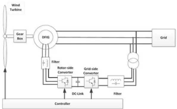
Among these, Type C and Type D are more popular than the former two because of the disadvantages mentioned in [2]. These wind turbine uses Wound Rotor Type Induction Generators (WTGS) which are commonly known as Doubly-Fed Induction Generators (DFIG). These machines are controlled by a converter connected at the rotor, where the power is small fraction, approximately equal to the slip of the stator power. A variable speed wind turbine-generator system schematic is shown in figure 1.
Figure 1. DFIG Wind Turbine Scheme.
Since, the rotor of the DFIG is connected to the grid through power converters, this makes the generator highly sensitive towards the disturbances of the grid. In this paper, the behaviour of the wind turbines are studied through various simulations done in the LABview environment.
This paper is organized in three sections. In the first section, wind turbine modelling is described along with the control technique implemented. In the second section, various voltage dips and fault conditions are described. Finally, in the third section, LABview used simulation results are presented.
II.
W
INDT
URBINEM
ODELLINGThe Wind Turbine Model is composed of various systems, (i) Aerodynamic Model, (ii) Gear Train, (iii) Electrical Machine and Power Converter and (iv) Control System as shown in figure 2.
Figure 2. Block Diagram of the WTGS [2].
A. Aerodynamic Model [3]
A WTGS is a structure that transforms the kinetic energy of the incoming air stream into electrical energy. The conversion takes places by using two devices. The first one is the extraction device, which harvests the mechanical power by the wind stream turning the wind turbine rotor. The other one is the generator which transforms the rotational mechanical power to electrical power. The relationship between the mechanical input power and the wind speed passing through a turbine rotor plane can be written as follows [3]:
(1)
TSR, (2)
The Cp co-efficient in a wind turbine
aerodynamic model can be approximated by [3]:
(3)
(4)
where, β = pitch angle, a1 = 0.5176, a2 = 116, a3
= 0.4, a4 = 5, a5 = 21, a6 = 0.0068.
B. Gear Train [4]
The speed of a wind turbine is very low, approximately of the order of 10 to 12 rpm [4]. For generation of electricity at 50Hz, this speed has to be increased up to 1200 rpm. This task is accomplished by Gear Trains. A Grain Train comprises of high speed shaft, low speed shaft and gears.
For dynamic analysis, a gear train is represented by a six-mass model. But this increases time of simulation for the model. For this purpose, a gear train is approximated by a two-mass model which combines the inertia of blades, inertia of gears and inertia of low speed shaft in one variable; while the other variable combines the inertia of low speed shaft and inertia of the generator. Thus, mathematical model can be represented by:
(5)
(6)
C. Electrical Machine and Power Converter
DFIGs are the Wound type Induction Generators. For the dynamic modelling and transient analysis, [2, 5] describes the d-q model of the machine which is used for the simulation purpose.
(7)
(8)
(9)
(10)
(11)
(12)
(13)
(14)
(15)
(16) (17) (18) (19)
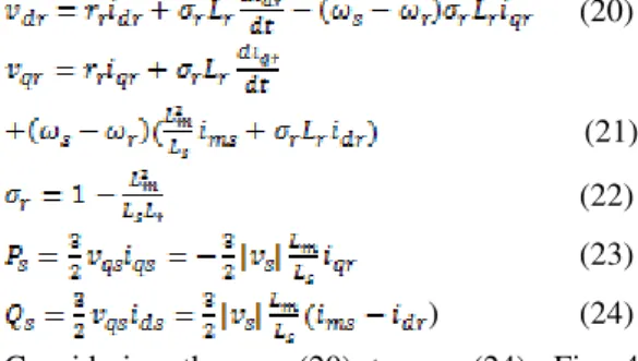
The wound rotor induction generator is controlled using a synchronously rotating reference frame, with the direct axis oriented along the stator flux vector position. In this manner, a decoupled control between the stator side active and reactive power can be achieved, as seen from the following [8], [9]: (20) (21) (22) (23)
) (24)
Considering the eq. (20) to eq. (24), Fig. 4 shows the control scheme, which the rotor current, stator current and voltage are measured orientated along the stator flux.
PI PI DQ/ ABC PWM Generator vma vmb vmc PI PI dq/ ABCs Stator Power Calculation αβ/ ABCs dq/ ABCr αβ/ abcr GRID Stator Flux Angle Calculation
1/Lm d/dt Q* s P* s Qs Ps i* dr i* qr iqr idr
Δvdr
Δvqr
vxr
vyr
ωs-ωr
θs-θr
ia ib ic iA iB iC
vA iA
vB iB
vC iC θr
iαr
iβr
iαs
iβs
ims φs
DFIG
Figure 3: Control Scheme of DFIG
III.
V
OLTAGED
IPSA
NDV
OLTAGEF
AULTSDFIGs are the controlled by the power converters connected to the rotor. This makes the machine excessively sensitive towards to grid disturbances. These disturbances are classified as the voltage drops and line faults.
A. Voltage Dips [2, 7]
A voltage dip is a sudden drop of one or more voltage phases. If such a dip occurs in all three phases of same magnitude, it is said to be a three-phase, symmetrical, or balanced dip if the drop is the same in the three phases. This fault could be caused by inrush currents at generator start-up or by a near short-circuit between the three phases and the ground.
B. Line Faults [2]
The single and three phase line faults are the special case of the voltage dips. In these conditions, there is complete dip of the voltage. During the line faults, high currents are induced in the machine causing the overheating of the system.
IV.
S
IMULATIONR
ESULTSIn [8], parameters of the 5 MW Horizontal Axis Wind Turbines are described. Taking these parameters into account, a LABview used program for the simulation has been developed. In this simulation, the following conditions were subjected
1. Three Phase Voltage Dip 2. Single Phase Voltage Dip 3. Three Phase Line to Ground Fault 4. Single Phase Line to Ground Fault
In the simulations, the wind turbine is subjected to nominal wind speed, 12m/s, and TSR is set to optimal value, 0.41.
A. Three Phase Voltage Dip
(a)
(b)
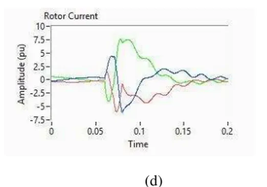
(d)
Figure 3: Simulation Results for three phase voltage dip: (a) Stator Line Voltage (pu), (b) Rotor Line Voltage (pu), (c) Stator Line Currents (pu), (d)
Rotor Line Current (pu)
In this simulation, all three phases of the grid are dipped by 40% of the rated value for 0.02 sec. This disturbance causes abrupt increase in the stator and rotor currents to 6 pu and 7.5 pu respectively, along with unbalance of the grid currents.
A. Single Phase Voltage Dip
(a)
(b)
(c)
(d)
Figure 4: Simulation Results for single phase voltage dip (a) Stator Line Voltage (pu), (b) Rotor Line Voltage (pu), (c) Stator Line Currents (pu), (d) Rotor Line Current (pu)
In this simulation, phase C of the grid is dipped by 40% of the rated value for 0.02 sec. This disturbance causes abrupt increase in the stator and rotor currents to 2 pu and 3.5 pu respectively, along with unbalance of the grid currents.
C. Three Phase Line to Ground Fault
(a)
(b)
(d)
Figure 5: Simulation Results for three phase line fault: (a) Stator Line Voltage (pu), (b) Rotor Line Voltage (pu), (c) Stator Line Currents (pu), (d) Rotor Line Current (pu)
In this simulation, the grid voltage is set 0 pu representing the short circuit of all three phases with the ground. This fault does not cause unbalance of the rotor voltage but unbalance of the currents both stator and rotor is observed with sharp increase to 21 pu and 22 pu respectively.
C. Single Phase Line to Ground Fault
(a)
(b)
(c)
(d)
Figure 6: Simulation Results for single phase line fault: (a) Stator Line Voltage (pu), (b) Rotor Line Voltage (pu), (c) Stator Line Currents (pu), (d) Rotor Line Current (pu)
In this simulation, phase C of the grid voltage is set 0 pu representing line to ground fault. This fault causes unbalance of the rotor voltage as well as unbalances of the currents both stator and rotor is observed with sharp increase to 6 pu and 9 pu respectively.
V.
C
ONCLUSIONIn this paper, a LABview based Wind Turbine Model has been described. This model is subjected to two types of grid disturbances; voltage dips and line faults. Only the extreme cases i.e. single phase and three phase voltage dips and faults are simulated. These simulation results show sharp increase in the amplitude of the control voltage and currents along with unbalances of the phases.
R
EFERENCES[1].Khan M.F., Khan M.R., Wind Power Generation
in India: Evolution, Trends and Prospects, Int.
Journal of Renewable Energy Development, 2 (3) 2013: 175-186.
[2].Abad Gonzalo, Lopez Jesus, Doubly Fed Induction Machine: Modelling and Control For
Wind Energy Generation, IEEE Press John
Wiley & Sons LTD, 2011.
[3].Jafarnejadsani Hamidreza, Pieper Jeff and Ehlers Julian, Adaptive Control of a Variable-Speed Variable-Pitch Wind Turbine Using Radial-Basis
Function Neural Network, IEEE Trans. on
Control Systems Technology, Vol. 21, No. 6, November 2013, pp. 2264-2272.
[4]. Johannes Cornelius Bekker, Efficient Modelling of a Wind Turbine System for Parameter
Estimation Applications, Stellenbosch
University, 2012.
[5].Chee-Mun ONG, Dynamic Simulation of Electric
Machinery Using Matlab/Simulink, Prentice Hall
[6].R. Pena, J. C. Clare, G. M. Asher, Doubly fed Induction Generator Using Back-to-Back PWM Converters and its Application to Variable-Speed
Wind-Energy Generator, IEE Proc.-Electr.
Power Appl., Vol. 143, No. 3, May 1996, pp. 231-241.
[7].A. Babaie Lajimi, S. Asghar Gholamian, M. Shahabi, Modeling and Control of a
DFIG-Based Wind Turbine During a Grid Voltage Dip,
ETASR – Engineering, Technology & Applied Science Research, Vol. 1, No. 5, 2011, pp. 121-125.
[8].J. Jonkman, S. Butterfield, W. Musial, G. Scott,
Definition of 5-MW Reference Wind Turbine for
Offshore System Development, Technical Report,
NREL/TP-500-38060, February 2009.
![Figure 2. Block Diagram of the WTGS [2].](https://thumb-eu.123doks.com/thumbv2/123dok_br/16302821.186242/2.892.108.442.492.700/figure-block-diagram-wtgs.webp)