The International Journal of Multimedia & Its Applications (IJMA) Vol.3, No.2, May 2011
Wan Mohd Rizhan Wan Idris
1, Elissa Nadia Madi
1, Md Yazid Mohd Saman
2 1Faculty of Informatics, Universiti Sultan Zainal Abidin, Malaysia wmrizhan@unisza.edu.my, elissa@unisza.edu.my
2Faculty of Science and Technology, Universiti Malaysia Terengganu, Malaysia
yazid@umt.edu.my
A
BSTRACTVirtual reality (VR) has been utilized in various applications such as in architecture, medicine, advertisement, business, entertainment, and education. In the world of simulation, VR software allows users to visualize, manipulate and interact with the computers and complex data. However, developing VR environments is costly and expensive. Highly-technical persons are needed to create the virtual objects from scratch. Once a virtual system is created, managing and modifying it creates further problems. There is a need for non-technical users to be able to create and modify their own virtual environments. This paper discusses a systematic technique to develop dynamic virtual environments and to manage virtual objects in their virtual environment. The technique is called hierarchical, tree-structured approach. To implement the technique, object-oriented programming language was used such as Java, Java 3D and Java Swing. For the usability and performance of the technique, a virtual environment has been created to become as case study. The tool has been perceived as an easy tool to use, especially for an environment in education.
K
EYWORDSVirtual Reality, Virtual Environment, Virtual Object, Tree Structure.
1.
I
NTRODUCTIONThe existence of virtual reality (VR) systems nowadays is resulted mostly by the development of computer technology especially in computer graphics area. Many fields such as architecture, medicine, advertisement, business, entertainment and education have explored and utilized the VR systems [1]. The existence of applications or systems based VR has changed humans’ perceptions, working styles and behaviors toward better effectiveness.
The International Journal of Multimedia & Its Applications (IJMA) Vol.3, No.2, May 2011
1.1. VOs, VEs and Other Components of VR
One of the important components in VR is virtual object (VO) [3]. VO refers to a 3D model or 3D object that exists in 3D space [6]. It can also be 2D objects. Many VOs are available online and ready to use. Users may download for free or purchase the ready-made VOs to be used in the VR applications. Some of the ready-made VOs available on the internet are shown in Table 1. Figure 1 shows several examples of VOs.
Table 1. Some URLs For The Ready-Made VOs
URLs Descriptions
http://www.amazing3d.com Provides services to build 3D models or VE for multimedia project, movie, animation, video game, magazine, website, 3D simulator and accident reconstruction.
http://www.3dmodelfree.com/ Offers free 3D models for home decorations including furniture, cookware, bathroom products, electronics and outdoor.
http://archive3d.net/ Offers free 3D models for categories of doors and windows, structures, companies and collections and people.
http://www.sharecg.com/ Offers products of 3D models, tutorials, animation and art. http://www.planit3d.com/source
/meshes_files/meshes.htm
Provides free 3D products of workshop, seating, household, transport, furniture, aviation, aquatics and plant.
Figure 1. Several examples of VOs
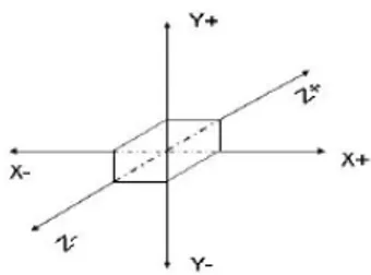
Another important component in VR is virtual environment (VE). VE is a complete 3D computer environments containing 3D and possible also 2D objects [6][1]. Therefore, there is a need to understand the coordination system to locate precisely the VOs in the VE. The coordination of x, y and z does not have gravity. The movements of the VOs in the VE are manipulated and controlled by the values of x, y and z. The x, y and z can also give the values of width, height and depth of the objects. Figure 2 illustrates the coordination of x, y, and z.
The International Journal of Multimedia & Its Applications (IJMA) Vol.3, No.2, May 2011
There are three other components in VR; viewing, walkthrough and manipulation. Viewing component enables all operations or tasks exercised in the VE to be visualized. In general, the viewing component can help explain the usage of terms; field of view; position and orientation; and distance of the objects. It is possible for the VR systems having several viewings or commonly pointed out as multi-views or multi-displays. Walkthrough component allows users to explore and navigate in the VE [3]. The users may go forward and backward or may turn left and right as if they walk or run in the real environment. It is suitable for the visualization and evaluation purposes in the construction, tourism and research fields. Manipulation component refers to the users’ interactions with VOs in the VE [3]. Some examples of activities describing this component are selecting an object, changing the position and orientation of an object, rotating and scaling an object. This component mainly highlights the particular ways users interact with VOs in VE.
1.2. Motivations
Normally, the 3D objects are constructed and modeled in various forms and shapes using 3D Tools such as 3ds Max, AC3D, Alladdin4D, Cinema4D, LightWave 3D, Maya or other 3D Tools [8] which are commercially available in the market. However, the high costs of the tools become the main issue. They also need highly technical efforts as well as relevant knowledge in creating a 3D object. Users need to spend sufficient times to complete a VO as desired. Users may feel frustrated when the desired form and shape of VO cannot be produced on time.
Typically, the complete VOs and/or ready-made VOs are placed in their VEs using the 3D Tools as well. The provided utilities in the 3D Tools may arrange the VOs in terms of locations and orientations. To locate accurately a VO at a particular place in the VE, normally the VO needs to be loaded one-by-one into the system. Therefore, another study mechanism is needed to manage and arrange the VOs in the VE especially when involving many VOs in a certain time. Improper management of the VOs can cause the VE to be crowded with the undesired VOs. Indirectly, this matter also contributes to delivering information unsystematically.
Sometimes, the VOs have links to other sub-VOs or sub-information. They are connected among them directly through files or URL. Improper management of the links will cause the sub-VOs or the sub-information cannot be accessed. This situation reveals to the users about the weaknesses of the operability and applicability for the system. These weaknesses may reduce the numbers of users to use the system.
Adding new information, deleting undesired information and editing existing information are crucial activities needed for modifications of the VOs in the VE. However, such modifications are limited and difficult in the VE which is full with many VOs. The change of a certain VO may affect the other VOs in the VE. Thus, the important information that should be perpetual is changed as well.
In this paper, we present the related works in Section 2 focusing on the managing VEs or VOs techniques. The proposed technique called Hierarchical, Tree-Structured Approach is discussed in detail in Section 3. The modules involved to create dynamic VEs and a case study are presented in Section 4. Section 5 describes on results and discussions for the created VEs using the proposed approach. We conclude our paper with conclusions and future works.
2.
R
ELATEDW
ORKSThe International Journal of Multimedia & Its Applications (IJMA) Vol.3, No.2, May 2011
have utilized pre-made files for creating VOs and VEs, walkthrough mechanism for navigation in the VE, rotation operation for manipulation of VOs and single-view mode for visualization [9]. In Virtual Community Trials Platform, a walkthrough method called Community 3D Walkthrough System has been proposed for moving, recording key walkthrough position nodes and playing back 3D animation with a walkthrough path. Only single-view mode has been utilized for visualization [10].
In V-REALISM system [11], a tree structure is used to manage and manipulate the imported geometric models in the VE. The models can be classified into environment model and system model in the tree structure. The environment models are used to simulate the maintenance environment and facilitate the visualization and exploration. The system models are further decomposed into component and subassembly models. Each component model is represented as a geometric mesh surface model which is displayed as a set of triangular surfaces. The smallest unit of a geometric model is triangular surface that is depicted as “TriUnit” in the hierarchy [11]. This system however can produce only a VE in a certain time.
Yuan et al. [12] have proposed assembly guidance techniques using the Virtual Interaction Panel (VirIP) and the Visual Assembly Tree Structure (VATS). VirIP is used to track the real-time interaction pen using a Restricted Coulomb Energy (RCE) neural network. VATS is used to represent the assembly sequences of complex products. VATS specifically works for management of assembly information and retrieval for the AR-assisted assembly guidance system. VATS comprises nodes that represent the assembly information such as geometric properties of an assembly part, sub-assembly and so on.
The sample tree proposed by Klein et al. [13] is used to store a number of polygons in a scene for rendering complex environment. The rendering process that provides caching mechanism allows only few nodes to be loaded from one frame to the next frame. This caching mechanism has employed the notion “Area Of Interest” (AOI) to use and render the objects in corresponding area.
Meanwhile, Java 3D features have been used as main hierarchy structure in managing and creating the virtual anatomic models [16]. The scene graph concept has been used to represent the multi-modal anatomy models. Group node in the structure is similar to Java 3D scene graph TransformGroup node and Geometry nodes are composed by the geometry node in Java 3D with some functions needed by other modal data.
The prior researches have utilized the tree structure in VR applications for certain tasks as described above. The use of the tree structure however, is not optimally or fully implemented for developing and managing VOs and VEs. In this paper, a technique using the tree structure for developing dynamic VEs as well as managing VOs is discussed in detailed.
3.
H
IERARCHICAL,
T
REE-S
TRUCTUREDA
PPROACHThe International Journal of M
Figu
Through mathematical definition
T = {r}
With the following properties:
• A designated node of the
• The remaining nodes are tree.
For convenience to denote the tree
T ={r,
The other important terms [17] ca
• The degree of a node is th the degree of tree T is n.
• A node of degree zero has
• Each root ri of sub-tree Ti a similar manner.
• The root node r of tree T term grandparent is define
• Two roots ri and rj of disti
The implementation of the tree st main VE. The sub-nodes in the tre parent node may turn out as VE represents as VO.
Our approach allows VOs to be s can be made when child nodes o case, the child nodes are said to b parent nodes that contain of their c
of Multimedia & Its Applications (IJMA) Vol.3, No.2, May
gure 3. Elements In A Tree Structure
n [17], a tree T is a finite, non-empty set of nodes,
}∪∪∪∪ T1∪∪∪∪T2∪∪∪∪ …∪∪∪∪ Tn (1)
e set, r, is called the root of the tree; and
re partitioned into n 0 subsets, T1, T2,..., Tn, each o
ree T, the following notation is used,
r, T1, T2,..., Tn} (2)
can be produced from (2):
s the number of sub-trees associated with that node. F
as no sub-trees. Such node is called a leaf.
iof tree T is called a child of r. The term grandchild
is the parent of all the roots ri of the sub-trees Ti, 1 < ined in a similar manner.
istinct sub-trees Ti and Tj of tree T are called siblings.
structure through our approach allows the root node, tree may represent the other VEs, T1, T2,..., Tn or VO VE and child node may become VO. The leave no
e split into a number of categories or groups. The cat or sub-nodes are inserted under a particular parent n be grouped or classified in their own parent nodes’ ca ir child nodes are defined as a collection of groups or c
y 2011
of which is a
. For example,
ld is defined in
1 < i n. The
, r to become Os. Basically, node certainly
The International Journal of Multimedia & Its Applications (IJMA) Vol.3, No.2, May 2011
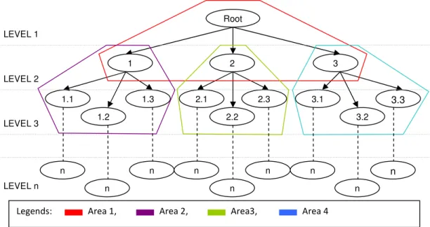
Categorizing the objects may also produce a number of levels or depths. Figure 4 shows the nodes in the tree structure that can be split into a number of groups based on parent-child concept. Each group then is called Area of Interest (AOF). For instances, Area 1 canvases the root node as parent while nodes 1, 2 and 3 as its children; Area 2 contains node 1 as parent node while its children are nodes 1.1, 1.2 and 1.3; and so do for the other areas. From the results, the VOs and VE can be defined and created successfully to be placed in the VR system. In this case, any parent node will be a VE while the child nodes will turn out to be the VOs in the VE (parent node).
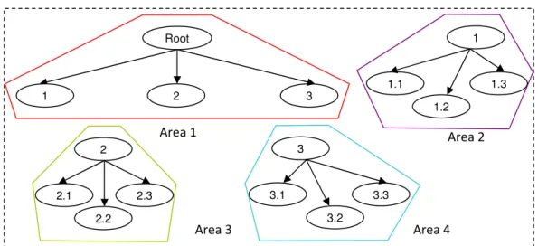
More details of information can be inserted especially for each VO in each area using our technique. By separating the areas (Figure 5), all nodes that resident inside each area seem more obvious without much complexity. The VOs perhaps may get hold of complete descriptions to be displayed and delivered as useful knowledge.
Besides, any modification or change on either information or VOs especially in terms of their positions and orientations can be made independently and easily. The modification only affects at the particular infected area. The rest of areas are not influenced by the modification.
A VO in the tree structure can also be reused or repeated. There is no limitation in the duplication of VOs. The duplicated VO then can be manipulated to produce a unique VO that differs from the other VOs. For such purpose, a mechanism in our technique to manipulate the VOs in terms of rotation, translation scale is used.
Through our technique, the VOs is managed and arranged in synchronized. A systematical flow of VOs’ node can be seen in the tree structure from the root node till the leaves nodes. Each area of interest produced according to parent-child concept is managed in sorted. Therefore, it leads to the synchronization of VEs.
Figure 4. Levels in the tree structure Root
3 2
LEVEL 1
LEVEL 2
1
1.1
1.2
1.3 3.1
3.2
3.3
2.1
2.2 2.3
LEVEL 3
LEVEL n n
n
n n
n
n
n
n n
The International Journal of Multimedia & Its Applications (IJMA) Vol.3, No.2, May 2011
Figure 5. Areas of interests in tree structure
4.
E
XPERIMENTSAs an experiment, modules involved in the creation and management of VEs, topic of amino acids group as a case study, type of VO file format used in the VR system and methods to develop VEs for the case study using the utilized approach are explained in detailed.
4.1. Modules of Creating and Managing Virtual Environments
There are four modules involved in creating dynamic VEs and managing VOs in VE as shown in Figure 6.
Module 1: Initializing interface of system (Loading Editor) Step 1: Finding & Selecting VOs
Step 2: Listing Names of VOs
Step 3: Displaying Preview Screen of VOs
Module 2: Developing a tree data structure (Hierarchical, Tree-Structured Editor) Step 1: Adding, removing and updating VOs
Step 2: Creating graphical tree structure Module 3: Organizing VOs (Organizing VOs Editor)
Step 1: Multi-Monitor Screens Step 2: Translation & Scale operations Step 3: Recording VOs’ Information Module 4: Viewing VE (Viewing Editor)
Step 1: Single-View & Multi-Views Step 2: Walkthrough in VE
Step 3: Manipulation of VOs
Figure 6. Four modules involved in creating and managing VEs
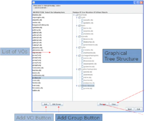
In the first module, an interface of virtual reality system called Loading editor is initialized. This interface allows users to search the location of VOs either in users’ computers or in the server and select the desired VOs to be loaded in the system; list the names of VOs that are successfully loaded; and display the sample of VOs selected from the list.
Root
3 2
1
3
3.1
3.2 3.3
Area 1 Area 2
Area 3 Area 4
2
2.1
2.2 2.3
1
1.1
1.2
The International Journal of M
The second module provides the The users can create the graphica this editor such as adding new V unneeded VOs and clearing all VO
Organizing VOs editor in the th position and orientation. The user VOs at the desired places. Each m and perspective views. Through tr VO at new location in the VE description, parent, path, location file with extension *.hevo for refe need to rebuild the VE from the be
The last module allows the users multi-views mode. They can walk mouse is used to allow the users m and 10 show the interfaces of ed described above.
Fig
of Multimedia & Its Applications (IJMA) Vol.3, No.2, May
he use of data structure using hierarchical, tree-struct ical tree structure through several types of operations
VOs in the tree structure, adding new group of VO VOs in the tree structure.
third module works to manage the VOs in the VE rs can view a VE in multi-monitor screens to precise monitor screen projects different viewing such as fro translation and scale operations, the users can move
and resize VO. Information about VOs such as f on, scale and rotation also can be saved systematicall eference, distribution and display in future. Thus the beginning.
rs to view the final results of VEs either in single-vi alkthrough in the VE using the arrow keys on the ke s manipulating and interacting with VOs in the VE. F editors in the VR system which implement the four
igure 7. Interface of loading editor
y 2011
uctured editor. ns provided in Os, removing
E in terms of sely locate the front, left, top ve the selected file, caption, ally in the text e users do not
The International Journal of M
Figure 8. In
Figure
Fig
4.2. Amino Acids Group
A topic of amino acids group has structured approach. Amino acids
of Multimedia & Its Applications (IJMA) Vol.3, No.2, May
Interface of hierarchy, tree-structured editor
re 9. Interface of organizing VOs editor
igure 10. Interface of viewing editor
as been chosen in testing the VR system using hierar ds are small molecules that may structure proteins [18]
y 2011
The International Journal of Multimedia & Its Applications (IJMA) Vol.3, No.2, May 2011
forming short polymer chains called peptides or polypeptides in turn, they construct proteins. In fact, the amino acids become the basic structural building units of proteins [19]. All molecules contain three important parts; an Amine group, a Carboxyl group and R group. Both the Amine group and the Carboxyl group belong to all amino acids. However, R group varies for individual amino acid. In fact, each molecule can be recognized through this R group. The Amine group contains elements NH3+ while the Carboxyl group contains COO- [18]. A different side chain is represented by R group specifically to each amino acid. Figure 11 shows the basic structure for amino acids.
Figure 11. The structure of all amino acids
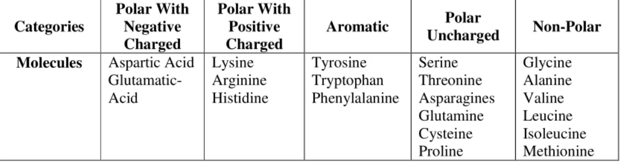
There are twenty amino acids encoded by the standard genetic code which are Argynine (Arg/R), Glutamine (Gln/Q), Phenylalanine (Phe/F), Tyrosine (Tyr/Y), Lysine (Lys/K), Glycine (Gly/C), Alanine (Ala/A), Histidine (His/H), Proline (Pro/P), Glutamic Acid (Glu/E), Aspartic Acid (Asp/D), Threonine (Thr/T), Methionine (Met/M), Leucine (Leu/L), Asparagine (Asn/N), Isoleucine (Ile/I), Tryptophan (Trp, W), Serine (Ser/S), Cysteine (Cys/C), Valine (Val/V) [19, 20, 21]. The twenty amino acids then are classified into five categories as shown in the Table 2.
Table 2. The categories of amino acids
Categories
Polar With Negative Charged
Polar With Positive Charged
Aromatic Polar
Uncharged Non-Polar
Molecules Aspartic Acid Glutamatic-Acid
Lysine Arginine Histidine
Tyrosine Tryptophan Phenylalanine
Serine Threonine Asparagines Glutamine Cysteine Proline
Glycine Alanine Valine Leucine Isoleucine Methionine
4.3. OBJ File Format
In the VR system, ready-made VOs for the amino acids group have been utilized. The type of file format for the VO is Wavefront or OBJ file format. Wavefront or OBJ file format is a geometry definition file format. It is used for its advanced visualizer animation package [22] that purposes especially in storing and exchanging 3D data [23]. Many 3D graphics application vendors can utilize and support the OBJ file format [22].
This file format produces two types of files for each VO which in respect contain the extensions of (*.obj) for object file and (*.mtl) for material file [25, 26]. Both files always need to be along with each other.
Hydrogen
Amine Carboxyl
The International Journal of M
4.4. Development of Amino A
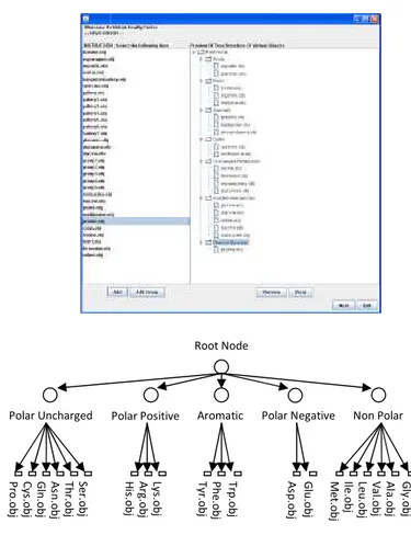
Through our approach, several classification of the amino acids g structure. The first layer is where to a Gallery Building and five cl with Negative Charge, Polar Unch group, new group utility in the VR on the classes of amino acids. It i In the last layer, all children o respectively. Figure 12 depicts the
Figure 1
Through the tree structure, the VO nodes that have been parents in e VOs. Meanwhile, the VOs refer t the groups have been determined t
Let the root denoted as r, Polar Polar Negative as VO4 and Non P as VOTn,i where n={1, 2, 3,...} an Pre-Order Traversal is used as fol visiting all the nodes of a tree. It w
Polar Uncharged P ro .o b j C y s. o b j G ln .o b j A sn .o b j T h r.o b j S e r.o b j
of Multimedia & Its Applications (IJMA) Vol.3, No.2, May
Acids Group Virtual Environments
al VEs of the amino acids have been created ba s group. In this case, there are three layers in the hier re the root takes place. The root contains six children classes of the amino acids i.e: Polar with Positive C ncharged, Non-Polar and Aromatic. To develop the m VR system is used. The name of new group then is ch t is because the group has no model to represent itsel or VOs are placed and positioned according to t the tree structure for the amino acids group using our a
12. Tree structure of amino acids group
VOs and VE components are able to be identified. In n each group become the VEs which are inhabited b
r to the contents of the parents’ children. Therefore d to be the VEs.
ar Uncharged as VO1, Polar Positive as VO2, Aroma Polar as VO5. Each leave node beneath its parent nod and i={1, 2, 3,...}. For storing hierarchical data in d follow (3) using (2). A Pre-Order Traversal is an effic t will trace the outline of the tree starting from the upp
Root Node
Aromatic Polar Negative Non Polar
G ly .o b j P h e .o b j T rp .o b j A sp .o b j G lu .o b j T y r.o b j M e t.o b j Ile .o b j Le u .o b j V a l.o b j A la .o b j Polar Positive A rg .o b j Ly s. o b j H is .o b j y 2011
based on the erarchical tree en which refer Charge, Polar model of each changed based self in the VE. their groups r approach.
n this case, all by their own e the root and
The International Journal of M
to the root, identifying nodes as tr is the root node.
4.5. Outputs of Amino Acids G
As illustrated in Figure 13, there These categories are placed inside in the Gallery refer to Polar Positi and aromatic. Each of them has i their own VEs when user activate and Figure 14(e) show the VEs fo
Figure 1
(a) VE of polar positive
of Multimedia & Its Applications (IJMA) Vol.3, No.2, May
travel downward on the left side of the node. The fir
s Group Virtual Environments
re are a Gallery and five other categories of amino ac ide the Gallery as if they are exhibited in it. These fiv sitive Charge, Polar Negative Charge, Non-Polar, pola s its own sub-nodes or child nodes. Thus the categori ates them. Figure 14(a), Figure 14(b), Figure 14(c), F for each category and their VOs.
e 13. A gallery and five main categories
ve (b) VE of non-pol
y 2011
first node here
acids in a VE. five categories lar uncharged ories can have , Figure 14(d)
The International Journal of M
(c) VE of polar negative
Figur
5.
R
ESULTS&
D
ISCUSSIONAfter testing the selected topic in analysis for the outputs is then im quantitative method is used to ob system. Meanwhile the qualitative using the proposed approach.
5.1. Quantitative Analysis
The input data used in the VR molecules and the primitive ob representing the groups of molecu an amount of storage when it is a projected VE in the VR system.
of Multimedia & Its Applications (IJMA) Vol.3, No.2, May
(d) VE of polar uncha
(e) VE of aromatic
ure 14. VEs for the categories of VOs
NS
in the VR system using the hierarchical, tree-structure implemented through qualitative and quantitative m obtain the amount of capacities generated by each VE ive method is implemented to evaluate the usability of
R system contains of the ready-made VOs for repre objects created by the tool provided in the VR cules. Each VE comprising a number of VOs beneath s activated. Table 3 shows the total of storage genera
y 2011
harged
red approach, methods. The VE in the VR of VR system
The International Journal of Multimedia & Its Applications (IJMA) Vol.3, No.2, May 2011
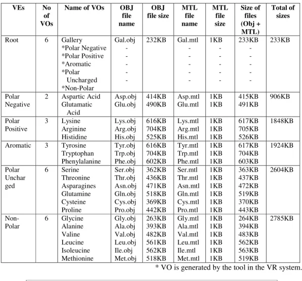
Table 3. The total of storage generated for each projected VE
VEs No
of VOs
Name of VOs OBJ
file name OBJ file size MTL file name MTL file size Size of files (Obj + MTL) Total of sizes
Root 6 Gallery
*Polar Negative *Polar Positive *Aromatic *Polar Uncharged *Non-Polar Gal.obj - - - - -
232KB Gal.mtl - - - - - 1KB - - - - - 233KB - - - - - 233KB Polar Negative
2 Aspartic Acid Glutamatic Acid Asp.obj Glu.obj 414KB 490KB Asp.mtl Glu.mtl 1KB 1KB 415KB 491KB 906KB Polar Positive
3 Lysine Arginine Histidine Lys.obj Arg.obj His.obj 616KB 704KB 525KB Lys.mtl Arg.mtl His.mtl 1KB 1KB 1KB 617KB 705KB 526KB 1848KB
Aromatic 3 Tyrosine Tryptophan Phenylalanine Tyr.obj Trp.obj Phe.obj 616KB 704KB 602KB Tyr.mtl Trp.mtl Phe.mtl 1KB 1KB 1KB 617KB 704KB 603KB 1924KB Polar Unchar ged
6 Serine Threonine Asparagines Glutamine Cysteine Proline Ser.obj Thr.obj Asn.obj Gln.obj Cys.obj Pro.obj 362KB 436KB 471KB 518KB 369KB 442KB Ser.mtl Thr.mtl Asn.mtl Gln.mtl Cys.mtl Pro.mtl 1KB 1KB 1KB 1KB 1KB 1KB 363KB 437KB 472KB 519KB 370KB 443KB 2604KB Non-Polar
6 Glycine Alanine Valine Leucine Isoleucine Methionine Gly.obj Ala.obj Val.obj Leu.obj Ile.obj Met.obj 263KB 393KB 482KB 561KB 562KB 518KB Gly.mtl Ala.mtl Val.mtl Leu.mtl Ile.mtl Met.mtl 1KB 1KB 1KB 1KB 1KB 1KB 264KB 394KB 483KB 562KB 563KB 519KB 2785KB
* VO is generated by the tool in the VR system.
233 906 1848 1924 2604 2785
0 500 1000 1500 2000 2500 3000
VEs
Non-Polar
Polar Uncharged
Aromatic
Polar With Positive Charged
Polar With Negative Charged
The International Journal of M
Based on Figure 15, the bar chart higher storages will be generated. VO and 5 others primitive VOs Negative Charged VE generates Meanwhile VE of Polar With Pos OBJ file format VOs. A capacity VOs. Polar Uncharged and No containing 6 VOs. Even the num higher capacity.
5.2. Usability Performance
A usability study on the VR syste effectiveness, efficiency and usab of forty two undergraduate studen study. The experiment had two s tested the system and took a re questionnaire to express their ex students during the interactions ha used to improve the system or ca The questionnaire had three sectio questionnaire utilized Likert scale
Figur
Figure 16 shows the mean scores the mean scores of the studied fac Knowledge”. The score in the fact
0 0.5 1 1.5 2 2.5 3 3.5 4 4.5 4.0476 3.92 M e a n S c o re s
of Multimedia & Its Applications (IJMA) Vol.3, No.2, May
art shows that the many uses of VOs in certain levels d. The root VE produces 233Kb for containing 1 OB s created using the tool provided in the VR system. tes capacity of 906Kb since it has 2 OBJ file fo
ositive Charged produces higher capacity which is 18 ty of 1924Kb is generated by Aromatic VE for 3 OBJ on-Polar VEs respectively produce 2604Kb and mber of VOs is equal but the more complex VOs w
stem in education has been conducted to evaluate in ability existed and performed in the system as desired
ents with specification in Biology field had been sele sample quizzes for the students to familiarize with real quiz. After the completion of the quiz, they experiences. Inconvenience and difficulties encount had been recorded. Identified factors for such proble can serve as references to design and develop the futu
tions; Demographic, Experience and System Usability le style.
ure 16. The results of usability study
es of the responses in the usability study of the system actors are above the level of point 3.000 except in the actor “Fun To Use” is 4.0476 which mean the respond
286 3.881 3.5952 3.4286 3.5238 2.3095 Factors Fact y 2011
ls or VEs, the BJ file format m. Polar With format VOs. 1848Kb for 3 BJ file format 2785Kb for will generate
n terms of the red. A number elected for the ith. They then y filled up a ntered by the lems could be uture systems. lity Scale. The
m. In general, he factor “Pre-ndents highly
The International Journal of Multimedia & Its Applications (IJMA) Vol.3, No.2, May 2011
have fun using the VR system. Almost respondents state their agreements that the system can help them in education with the mean scores 3.9286 in the factor “Help Learning”. In the factor “Suitable For Education”, the respondents agree that the VR system is suitable to be used in education with the mean scores 3.8810. At the level of point 3.5952 in the mean scores of the factor “Easy To Use”, the respondents respond that the system is easy to use. Meanwhile, the mean scores for the factor “Will Frequently Use” is at the level of point 3.5238 which mean the respondents are agree to use frequently the system in the future. They also can understand the subject due to the mean scores 3.4286 obtained for the factor “Understand Learning”. However, with the mean scores at 2.3095 for the factor “Pre-Knowledge” show that the respondents need to learn the system firstly before they are able to master it.
6.
C
ONCLUSIONThis paper has presented a systematic technique called hierarchical, tree-structured approach for creating dynamic VEs and managing VOs in VE. Through this approach, several crucial VEs for the amino acids group have been created. Users are able to visualize, interact with VOs and walkthrough in the VE. To develop dynamic VEs in the VR system, four modules have been explained in detailed. Quantitative and qualitative data have been collected respectively to examine the use of capacity for each projected VE and to evaluate the usability of VR system using the proposed approach. The findings have shown that the VR system utilizing the Hierarchical, Tree-Structured approach is useful for teaching, easy and fun to use. The respondents have also indicated that they could understand the subject better using the system. Therefore, this approach may breed better understanding among students in their learning. We believe that many applications from various fields can be produced using this study including gaming, manufacture, architecture, medicine, entertainment etc.
R
EFERENCES[1] Graces A., Quiros R., Chover M., & Camahort C. (2010) “Implementing Virtual Agents: A HABA-Based Approach”, The International Journal of Multimedia & Its Applications (IJMA). Vol.2, No. 4.
[2] Bell M.W., (2008) “Towards A Definition of Virtual World”, Journal of Virtual World Research. ISSN: 1941-8477. Vol. 1, No. 1.
[3] Nalbant G., & Bostan B. (2006) “Interaction In Virtual Reality”, 4th International Symposium of Interactive Medial Design (ISIMD).
[4] Sherman W. R., & Craig A.B. (2003) Understanding Virtual Reality, Morgan Kaufmann Publishers. P-17.
[5] Burdea G., & Coiffet P. (2003) Virtual Reality Technology. John Wiley & Sons. P-2.
[6] Troyer O.D., Kleinermann F.,& Ewais A. (2010) “Enhancing Virtual Reality Learning Environments with Adaptivity: Lessons Learned”, USAB’10 Proceedings of the 6th International Conference on HCI in Work & Learning, Life & Leisure: Workshop HCI & Usability Engineering Springer-Verlag Berlin, Heidelberg.
[7] http://www.ftsm.ukm.my/samn/PDFs/TH3813%20 01%20Pengenalan.pdf, Accessed on November 3, 2009.
[8] Leng J., (2001) “Scientific Examples of Virtual Reality and Visualization Applications”, UK High Performance Computing, Pages 1-13.
The International Journal of Multimedia & Its Applications (IJMA) Vol.3, No.2, May 2011
[10] Qiang L., Huanzhi L., Fei W., & Boyan C., (2004) “Virtual Community Trials Platform”, Journal Of International Archives Of Photogrammetry Remote Sensing And Spatial Information Sciences, Vol 35, (4), Pages 1144-1147.
[11] Li J. R., Khoo L. P., & Tor S. B., (2003) “Desktop Virtual Reality For Maintenance Training: An Object-Oriented Prototype System (V-REALISM)”, Elsevier-Computer In Industry, 52, Pages 109-125.
[12] Yuan M.L., Ong S.K., & Nee A.Y.C. 2006. Assembly Guidance in Augmented Reality (AR) Environments Using a Virtual Interactive Tool. International Journal of Production Research. Vol. 46, No. 7, 1745-1767.
[13] Klein J., Krokowski J., Fischer M., Wand M., Wanka R., & Heidi F. M. A. D., (2004) “The Randomized Sample Tree: A Data Structure for Interactive Walkthroughs in Externally Stored Virtual Environments”, MIT Press Journal, Vol. 13, No. 6, Pages 617-637.
[14] Huang S., Baimouratov R., & Nowinski W. L., (2004) “Building Virtual Anatomic Models Using Java3D”, Proceedings of the 2004 ACM SIGGRAPH international conference on Virtual Reality continuum and its applications in industry, Session: 7-3 Modeling, Pages 402 – 405.
[15] http://en.wikipedia. org/wiki/Tree_data_structure. Accessed on April 10, 2008
[16] Goodrich M. T., & Tamassia R., (2010) Data Structure And Algorithms In Java, John Wiley & Sons Inc, USA.
[17] Preiss B. R., (2000) Data Structure And Algorithms With Object-Oriented Design Patterns In Java, John Wiley & Sons, Inc, USA.
[18] Millar T., (2002) Biochemistry Explained: A Practical Guide To Learning Biochemistry, Gutenberg Press Ltd, Malta.
[19] Polanski A., & Kimmel M., (2007) Bioinformatics, Springer-Verlag Berlin Heidelberg, New York.
[20] Bhagavan N. V., (2002) Medical Biochemistry-Fourth Edition, Harcourt/Academic Press, Canada. [21] Pamela C. C., Richard A. H., & Denise R. F., (2005) Biochemsitry, Lippincott Williams &
Wilkins, USA.
[22] http://en.wikipedia.org/wiki/Obj, Accessed on August 6, 2008.
[23] http://www.fileformat.info/format/wavefrontobj/, Accessed on August 6, 2008.
Author
Wan Mohd Rizhan Wan Idris is a Multimedia lecturer in Faculty of Informatics under the department of Multimedia in Universiti Sultan Zainal Abidin, Terengganu, Malaysia. He obtained Master of Science in Computer Science from Universiti Malaysia Terengganu since 2010. His focused areas are on virtual reality, 2D and 3D animations.