Abstract—In this paper a new method for two link- robotic manipulator systems control using Neural Network, The first method is based on Proportional-Integral-Derivative controller, the second method is based on artificial Neural Network by PID controller for Two link- robot control with different load.
Index Terms—two link- robotic manipulator systems, Neural Network, PID controller
I. INTRODUCTION
development of robotic applications, in industrial therefore dynamic control of robot manipulators is one of the most important and challenging fields of robotics, in the recent years using intelligence control such as fuzzy control, Neural Network, Neuro Fuzzy and because that they can control nonlinear systems that would be difficult or impossible to model mathematically. In the recently years In Dynamic control of robot have been utilized in many researchers work in this area. Such as Lianfang Tian et al use a neural network approach for the motion control of constrained flexible manipulators robots [1]. Yi , et al have investigated the robustness and stability of a fuzzy logic controller applied to a robotic manipulator with uncertainties such as friction, unmodeled dynamics, and external disturbance etc [2], Kumbla et al have implemented hierarchical control on robotic manipulator using fuzzy logic [3].
Bannerjee, et al have used a Fuzzy Logic Controller to achieve position control of a two-link manipulator [4]. Adams, et al [5] has used GA to optimize the membership functions and rule bases of a multi-stage fuzzy PID controller with a fuzzy switch for robot control. Brudka, et al presented an intelligent robot control system which employs ultrasonic distance measurements, and for Consecutive stages of data processing they used to neural networks applications [6],
Adamiv, et al used neural networks application for mobile
robot control on predetermined trajectory of the road [7],
Ya-Chen , et al used an Fuzzy neural adaptive controller to
multiple-link robot control [8], Devendra P, et al used the
proportional plus derivative (PD) control with the PD
controller gain parameters optimized via Genetic Algorithm
Corresponding Author Leila Fallah Araghi, Assistant professor in, Electrical Engineering, Engineering Faculty Tehran University. (Email: [email protected])
M. H. koorayme, Professor, Electrical Eng. Dept, Tehran Iran (Email: [email protected])
(GA) And Fuzzy Logic for control of Two link- robot [9], Z.G. Zhang, et al report on the design and stability analysis of a simple quadruped running controller that can autonomously generate steady running with good energy efficiency and suppress.
Dongbing Gu, et al presented a new path-tracking scheme for a car-like mobile robot based on neural
Predictive control, they employed A multi-layer back-propagation neural network to model non-linear kinematics of the robot instead of a linear regression estimator in order to adapt the robot to a large operating range [10], Mathew L, et al studied on the implementation of several Intelligent control techniques as applied to the balancing of the inverted wedge problem. These included a basic four-input direct fuzzy controller (including the use of the nonlinear input term) and an adaptive fuzzy control technique known as the FMRLC [11].
II.DYNAMIC EQUATION OF TWO LINK- ROBOTIC MANIPULATOR SYSTEMS [12]
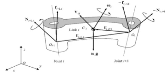
In this section we derive the equations of motion for an individual link based on the direct method has been derived, i.e. Newton-Euler Formulation. The motion of a rigid body can be decomposed into the translational motion with respect to an arbitrary point fixed to the rigid body, and the rotational motion of the rigid body about that point. The dynamic equations of a rigid body can also be represented by two equations: one describes the translational motion of the centroid (or center of mass), while the other describes the rotational motion about the centroid. The former is Newton's equation of motion for a mass particle, and the latter is called Euler's equation of motion.
Figure 1 shows all the forces and moments acting on link i.
Figure 1: Free body diagram of link i in motion
Let be
V
ci the linear velocity of the centroid of link i withreference to the base coordinate frame O-xyz, which is an inertial reference frame. The inertial force is then given by
Neural Network Controller for Two links- Robotic
Manipulator Control with Different Load
ci i
V
m
.
−
, wherem
i is the mass of the link andV
ci.
is the
time derivative of
V
ci.Based on D’Alembert’s principle, the equation of motion is then obtained by adding the inertial force to the static balance of forces in eq.( 1) so that
.
1 , ,
1 − + + − =0
− i ii i i ci
i f mg mV
f ,i=0,1,...,n (1)
i i
f
−1, And−
f
i,i+1are the coupling forces applied to link i by links i-1 and i+1, respectively, and g is the acceleration of gravity.Adding these terms to the original balance of moments we have: 0 ) ( ) ( ) ( . 1 , , , 1 , , 1 1 , ,
1 − +− − − × − +− × +− − × =
−i ii i i ici i i ici ii i i i i i
i N r r f r f I I
N ω ω ω
(2)
i i
N−1, and −Ni,i+1are the moment applied to link i by links i-1 and i+1, respectively.
If we consider two individual links robot, Let us obtain the Newton-Euler equations of motion for the two individual links.
Figure.2 Mass properties of two planar robots
From eq. (1) and (2), the Newton-Euler equations for link 1 are given by:
. 1 1 1 2 , 1 1 ,
0 − f +m g−m Vc =0
f (3) 0 ) ( ) ( . 1 1 2 , 1 1 , 1 1 , 0 1 , 0 2 , 1 1 ,
0 −N − r ×f + r ×f −I ω =
N c
(4)
Note that all vectors are 2 x 1, so that moment N i-1,i and the other vector products are scalar quantities. Similarly, for link 2: . 2 2 2 2 ,
1 +m g−m Vc =0
f (5) 0 ) ( . 2 2 2 , 1 2 , 1 2 ,
1 − r ×f −I ω =
N c
(6)
To obtain closed-form dynamic equations, we first
eliminate the constraint forces and separate them from the
joint torques, so as to explicitly involve the joint torques in
the dynamic equations. For the planar manipulator, the joint
torques τ1 and τ2 are equal to the coupling moments:
i i i
N−1, =
τ
(7)Substituting eq. (7) into eq. (6):
0 ) ( ) ( . 2 2 . 2 2 2 2 , 1
2 − × − − ω =
τ r c m Vc m g I
(8)
Similarly, eliminating
f
0,1 yields,0 ) ( ) ( ) ( ) ( . 1 1 2 1 , 0 . 1 1 , 0 2 2 1 , 0 . 1 1 1 , 0 2
1−τ − × + × + × + × − ω=
τ rc mVc r mVc rc mg r mg I
(9)
Next, we rewrite
V
ci,ω
ci andr
i−1,iusing joint displacementsθ
1,
θ
2 which are independent variables.Note that
ω
2 is the angular velocity relative to the basecoordinate frame, while
θ
2 is measured relative to link 1. Then, we have. 2 . 1 2 1 .
1
θ
,ω
θ
θ
ω
= = +(10)
The linear velocities can be written as
⎥ ⎥ ⎥ ⎦ ⎤ ⎢ ⎢ ⎢ ⎣ ⎡− = ) cos( ) sin( 1 . 1 1 1 . 1 1 1 θ θ θ θ c c c l l V (11)
{
}
{
}
⎥⎥ ⎥ ⎥ ⎦ ⎤ ⎢ ⎢ ⎢ ⎢ ⎣ ⎡ + − + + + − + + − = . . 2 2 1 2 1 2 1 2 1 1 . . 2 2 1 2 1 2 1 2 1 1 2 ) cos( ) cos( ) cos( ) sin( ) sin( ) sin( θ θ θ θ θ θ θ θ θ θ θ θ θ θ c c c c c l l l l l l V (12) 1 . 2 . 1 . 2 2 12 .. 1 111=H θ+H θ −hθ −2hθθ+G
τ (13) 2 . 1 .. 1 21 .. 2 22
2=H θ +H θ −hθ +G τ That: 2 2 2 1 2 2 2 1 1 1 2 1 1
11 ml I m(l l 2ll cos( )) I
H = c + + + c + c θ +
2 2 2 1
22
m
l
I
H
=
c+
(14) H11=m2(lc22+l1lc2cos(θ2))+I2
)
sin(
2 2 12
l
l
cθ
m
h
=
(15))
cos(
1 22 2
2
=
m
g
l
cθ
+
θ
G
III.NEURALNETWORK CONTROLLER BASED ON PID AND PD CONTROLLER [13, 14, 15, 16, 17]
This paper presents two strategies for achieving the control in two link- robotic manipulator systems. First one is based on Proportional-Integral-Derivative (PID) and second strategies are based on Neural Network controller based on PID controller both of these strategies are briefly described below:
PID stands for Proportional-Integral-Derivative. This is a type of feedback controller whose output, a control variable (CV), is generally based on the error (e) between some user-defined set point (SP) and some measured process variable (PV). Each element of the PID controller refers to a particular action taken on the error:
Proportional: error multiplied by a gain, Kp. This is an adjustable amplifier. In many systems Kp is responsible for process stability: too low and the PV can drift away; too high and the PV can oscillate. Integral: the integral of error multiplied by a gain, Ki. In many systems Ki is responsible for driving error to zero, but to set Ki too high is to invite oscillation or instability or integrator windup or actuator saturation Derivative: the rate of change of error multiplied by a gain, Kd. In many systems Kd is responsible for system response: too high and the PV will oscillate; too low and the PV will respond sluggishly. The designer should also note that derivative action amplifies any noise in the error signal.
The transform function of PID controller that used in this paper is [16]:
(17)
In this strategy PID controller is used in control of Two link- robotic manipulator systems, The block diagram of a PID controllers is shown in Figure 3.
System
T1 q1
T2 q2
PI D CONTROLLER
+
-PI D CONTROLLER
+
-+
-+
Figure 3: the schematic of PID Controller
Artificial neural network can be applied to various problems such as function approximation, pattern recognition, signal processing, classification, etc. There are typically two steps involved when using neural networks for control:
1-System identification 2-Control design
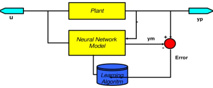
In the system identification stage a neural network model of the plant to be controlled is developed. Fig. 4 shows the block diagram representation of the system identification
stage. In the control design stage, the neural network plant model is used to train the controller.
u
Plant
Neural Network Model
+
-Learning Algoritm
yp
ym +
-Error
Figure 4: the structure of system identification stage
In learning process, neural network adjusts its structure such that it will be able to follow the supervisor. The learning is repeated until the difference between network output and the Supervisor is low. Implemented with a closed loop control. The difference NARMA-L2 controller, a multilayer neural network has been successfully applied in the identification and control of dynamic systems. System identification and control design are the two steps involved in using NARMA-L2 controller [17].
As with the model predictive control, the first step in using feedback linearization (or NARMA-L2 control) is to identify the system to be controlled. You train a neural network to represent the forward dynamics of the system. The first step is to choose a model structure to use. One standard model that has been used to represent general discrete-time nonlinear systems is the Nonlinear Autoregressive-Moving Average (NARMA) model:
)] 1 ( ),..., 1 ( ), ( ), 1 ( ),..., 1 ( ), ( [ )
(k+d =Nyk yk− yk−n+ uk uk− uk−n+
y
(18)
Where
u
(
k
)
the system is input, and y(k)is the system output. For the identification phase, you could train a neural network to approximate the nonlinear functionN
. This is the identification procedure used for the NN Predictive Controller.If you want the system output to follow some reference trajectory,y(k+d)= yr(k+d), the next step is to develop a
nonlinear controller of the form
)] 1 ( ),..., 1 ( ), ( ), 1 ( ),..., 1 ( ), ( [ )
(k =G yk yk− yk−n+ y k+d uk− uk−m+ u
r
(19)
The problem with using this controller is that if you want to train a neural network to create the function
G
that will minimize mean square error.As with the model predictive control, the first step in using feedback linearization (or NARMA-L2 control) is to identify the system to be controlled. You train a neural network to represent the forward dynamics of the system. The first step is to choose a model structure to use. One standard model that has been used to represent general discrete-time nonlinear systems is the Nonlinear )}
cos( )
cos( { )
cos( 1 2 2 1 2 1 1
1 1
1 m l g θ m g l θ θ l θ
G = c + c + +
1 )
(
+ + + =
NS S K S K K S
G D
Autoregressive-Moving Average (NARMA) model. The controller used in this section is based on the NARMA-L2 approximate model: ) ( )]. 1 ( ),..., 1 ( ), 1 ( ),..., 1 ( ), ( [ )] 1 ( ),..., 1 ( ), 1 ( ),..., 1 ( ), ( [ ) ( k u m k u k u n k y k y k y g m k u k u n k y k y k y f d k y + − − + − − + + − − + − − = + (20)
This model is in companion form, where the next controller input u (k) is not contained inside the nonlinearity. The advantage of this form is that you can solve for the control input that causes the system output to follow the reference
y
(
k
+
d
)
=
y
r(
k
+
d
)
. The resulting controller would have the form)] 1 ( ),..., 1 ( ), 1 ( ),..., 1 ( ), ( [ )] 1 ( ),..., 1 ( ), 1 ( ),..., 1 ( ), ( [ ) ( ) ( + − − + − − + − − + − − − + = n k u k u n k y k y k y g n k u k u n k y k y k y f d k y k u
(21) Using this equation directly can cause realization problems, because you must determine the control input based on the output at the same time, . So, instead, use the model:
) 1 ( )]. 1 ( ),..., ( , ) 1 ( ), 1 ( ),..., 1 ( ), ( [ ] ) 1 ( ),..., 1 ( ), ( ), 1 ( ),..., 1 ( , ) ( [ ) ( + + − − + − − + + − − + − − = + k u n k u k u k u n k y k y k y g n k u k u k u n k y k y k y f d k y (22) Where
d
≥
2
.
In the system identification stage a neural network
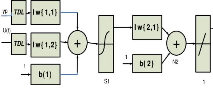
Plant model must be developed before the controller is used. The plant model predicts future plant outputs. The plant model has only one hidden layer.
The following figure shows the structure of a neural network representation [17, 16].
+
I w{ 2,1}
b{ 2} yp N2 TDL S1 TDL
+
I w{ 1,1}
I w{ 1,2}
b( 1) 1 1 y U(t) 1
Figure 5: the structure of neural network
The model predictive control method is based on the receding horizon technique. The neural network model predicts the plant response over a specified time horizon; figure 6 shows the controller block that has been used for predictive control: Controller ym
Neural
Network
Model
Plant
Optimization U U’Figure 6: the structure of predictive control
In the system identification stage, you develop a neural network model of the plant that you want to control. In the control design stage, you use the neural network plant model to design (or train) the controller. In each of the three control architectures described in this chapter, the system identification stage is identical.
The model predictive control method is based on the receding horizon technique. The neural network model predicts the plant response over a specified time horizon [14, 16];
The Neural Network controller based on PID controller has been used for control of two link- robotic manipulator systems, the block diagram of a Neural Network controllers based on PID controllers is shown in Figure 7.
Refrence Neural Network Model PID Controller + -+ -+ -output -+ + -+
Figure 7: the structure of the Neural Network controller based on PID controllers
The structure of Neural Network controller based on PID controller is shown in figure 8.
System
T1 q1
T2 q2
Neural Network Controller
Neural Network Controller
Figure 8: the schematic of Neural Network controller
In Neural Network controller as learning rules Modified Levenberg-Marquardt has been used [13, 15].
IV. SIMULATION RESULT
Figure 9: the schematic of the two link- robotic manipulator systems
Figure 10: the output of two link- robotic manipulator systems
In the first we considered that two link- robotic manipulator systems without is non load and then two link- robotic manipulator systems has been simulated with different load.
As the first method for closed loop control of two link robotic manipulator systems the PID controller has been used, figure 11 shows the non load simulation result:
Figure 11: the output of two link- robotic manipulator systems using PID controller without any load
Then the different load has been considered in closed loop control of link robotic manipulator systems by PID controller, figure 12 shows the simulation result with the different load.
Figure 12: the output of two link- robotic manipulator systems using PID controller with different load 3kg, 5kg, 7.5kg, 10kg
As the second method closed loop control of two link robot the Neural Network controller based on PID controller has been used, figure 13 shows the non load simulation result:
Figure 13: the output of two link- robotic manipulator systems using Neural Network controller based on PID controller without
any load
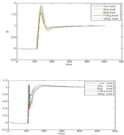
Then the different load has been considered in closed loop control of link robotic manipulator systems by Neural Network controller based on PID controller, figure 14 shows the simulation result with the different load.
Figure 14: the output of two link- robotic manipulator systems using Neural Network controller based on PID controller with
different load 3kg, 5kg, 7.5kg, 10kg
V. CONCLUSION
Network by PID controller for control of Two link- robotic manipulator systems.
References
[1] Lianfang Tian, Jun Wang, and Zongyuan Mao, "Constrained Motion Control of Flexible Robot Manipulators Based on Recurrent Neural Networks" ieee transactions on systems, man, and cybernetics—part b: cybernetics, vol. 34, no. 3, june 2004
[2] Yi, S.Y. and Chung, M., J., 1997, “A Robust Fuzzy Logic Controller for Robot Manipulators with Uncertainties”, IEEE Transactions on Systems, Man and Cybernetics, 27, No. 4, pp. 706 – 713.
[3] umbla, K.K. and Jamshidi, M., 1994, “Control of Robotic Manipulator Using Fuzzy Logic”, Proceedings of the Third IEEE Conference on Fuzzy Systems, Vol. 1, pp. 518-523. [4] Bannerjee, S. and Woo, P.Y., 1993, “Fuzzy Logic Control of
Robot Manipulator”, IEEE Conference on Control Applications, pp. 87-88.
[5] Adams, J.M. and Rattan, K.S., 2001, “Genetic Multi-Stage Fuzzy PID Controller with Fuzzy Switch”, Proceedings of the IEEE International Conference on Control Applications, pp. 323-327.
[6] Brudka, M. Pacut, A., "Intelligent robot control using ultrasonic measurements" Proceedings of the 16th IEEE Instrumentation and Measurement Technology Conference, 1999. IMTC/99.
[7] Adamiv, O. Koval, V. Turchenko, I., "Predetermined movement of mobile robot using neural networks" Proceedings of the Second IEEE International Workshop on Intelligent Data Acquisition and Advanced Computing Systems: Technology and Applications, 2003.
[8] Petropoulakis, L., "Intelligent control using agents and fuzzy behavioural structures": Proceedings of the 2000 IEEE International Symposium on Intelligent Control, 2000.
[9] Ya-Chen Hsu Guanrong Chen Malki, H.A., " Fuzzy neural adaptive controller design: with application to multiple-link robot control" IEEE International Conference on Neural Networks, 1997.
[10] Dongbing Gu and Huosheng Hu., “Neural Predictive Control for a Car-like Mobile Robot” International Journal of Robotics and Autonomous Systems, Vol. 39, No. 2-3, May, 2002 [11] Mathew L. Moore, John T Musacchio1, Kevin M. Passino,
“Genetic adaptive control for an inverted wedge: experiments and comparative analyses” Engineering Applications of Arti®cial Intelligence 2001.
[12] H. Harry Asada, “Introduction to Robotics” Massachusetts Institute of Technology.
[13] Hagan, M.T., Menhaj, M.B., “Training feed forward networks with the Marquardt algorithm”, IEEE Transactions on Neural Networks. 5:6, page(s): 989-993, 1994.
[14] Hagan, M.T., Demuth, H.B., Beale, M., Neural networks design’, Boston, 1996.
[15] Suratgar, A.A., Tavakoli, M.B., Hosseinabadi, A., “Modified levenberg-marquardt neural network training”, Enformatika, Page(s):46-48, 2005.
[16] Neural Network toolbox, Mtlab 2008.