ABSTRACT: The objective of this paper is to study the problem of the robotic manipulator operating on a non-ixed base by considering two dynamics scenarios. One in which the base is free to react in response to the robotic manipulator motion and the other in which the robotic manipulator moves its links in such a way to compensate the reaction forces on the platform so as to keep it stable. This approach is passive in the sense that no additional control effort has to be done to compensate the effects of the reaction forces on the platform. The methodology to approach the problem includes lab experiments aiming the dynamics analysis of a robotic manipulator operating on an ice platform on a glass table. The mathematical model of a satellite like a robotic manipulator is developed and then implemented in a computer by using the MaTlab software environment. The results of the computer simulations conirm that the control effort for the attitude control is larger for the case in which the links are in operation compared to the case in which the robotic manipulator is not working. For the passive case, the results conirm the attitude stability of the robotic manipulator platform when it is working. The passive case is that in which the robotic manipulator links are moving in a synchronized coniguration and in a reverse sense.
KEYWORDS: On-orbit operations, attitude control robotic manipulators, Non-inertial platform.
Interaction between Motions of Robotic
Manipulator arms and the Non-Fixed base
in On-Orbit Operations
Ijar M. da Fonseca1, Osamu Saotome2, Maurício N. Pontuschka3, Glaydson l.b. lima2,
Helosman V. de Figueiredo2, Narumi Seito1
INTRODUCTION
In this section it is discussed the robot on-orbit applications and some basic concepts regarding excitation of robotic platform in response to on-board robot activities as well as the concepts of robot and telerobot. he platform excitation due to the robotic manipulator activities falls within a wide area of the attitude dynamics and control, known as control structure interaction (CSI).
It is very risky and highly expensive to send humans into space missions for any kind of activity. Presently, there is a consensus towards replacing humans by space robots in the space activities. Robots are machines that can be replaced and improved thanks to the enormous advances of the information technology (IT). Robots represent an attractive option to replace humans in space. Operations that require robots are on-orbit rendezvous and docking/berthing (RVD/B) of spacecraft (NASA 2005, Kawano et al. 1989, 1994, 1998, 2001; Mokuno
et al. 1995), assembling of space vehicle in space (as done when assembling the International Space Station — ISS), on-orbit servicing, OOS (Skaar and Ruoff 1994), for maintenances and assistances, scientiic experiments in space, missions for planetary explorations, among others. his is the direction of the future of the space exploration: to use intelligent robots and systems of robots with capability of local decision taking without the need for ground station commands/decision taking. There are some important differences between the ground-based and space-based robotic manipulators dynamics. he ground-based robotic manipulators may work on ixed
1.Instituto Tecnológico de aeronáutica – Departamento de Mecatrônica – Divisão de Mecânica aeronáutica – São José dos Campos/SP – brazil. 2.Instituto Tecnológico de aeronáutica – Divisão de Engenharia Eletrônica – São José dos Campos/SP – brazil. 3.Pontifícia Universidade Católica de São Paulo – Departamento de Computação – São Paulo/SP – brazil.
Author for correspondence: Ijar M. da Fonseca | Instituto Tecnológico de aeronáutica – Departamento de Mecatrônica – Divisão de Mecânica aeronáutica | Praça Marechal Eduardo Gomes, 50 – Vila das acácias | CEP: 12.228-900 – São José dos Campos/SP – brazil | Email: [email protected]
platforms in the Earth gravitational environment. On the other hand space-based robotic manipulators work on movable and apparently weightless platforms in microgravity environments. The ground-based robotic manipulator platform may not move in response to the motion of the robotic manipulators as they are ixed while they execute required tasks. he on-orbit environment is characterized by microgravity and, because of this, the robotic manipulator base is not ixed in space (in inertial sense). It is free to move in response to the motion of the robotic manipulator when it is in activity.
On-orbit activities (Pedersen et al. 2004) may be external to the space vehicle (extravehicular activities — EVA) or internal to the spacecrat. Other space activities refer to towing a satellite from one orbit to another or simply docking with a spacecrat aiming maintenance operations. he scenario for an on-orbit operation may be as that of one robotic manipulator docked or berthed in a spacecrat and working on it. Depending on the work to be executed, the spacecrat becomes the robotic manipulator base and it may move in response to the manipulator links motion while it performs tasks. In such scenario the attitude and the translational motion of the spacecrat may be disturbed, requiring attitude and orbit control.
A telerobot difers from the autonomous robot because it involves a human located on a central control station to command the robot. he nowadays tendency to use autonomous robots requires more security to assure the success of on-orbit operations. The success of missions may be achieved by minimizing collision risks in the robot space work, by controlling the robot’s hand applied forces, preventing malfunctioning of the hardware and sotware through risk analysis, as well as dynamical analysis to detection/prevention, and controlling the robotic manipulator platform excitation due the robotic operations. To close the discussion about this problem, it can be stated that the study of the response of the non-inertial platforms to the robot motions is fundamental for the success of all the space operations to be taken in the microgravity environment. One of the main requirements from the control area is to maintain the robotic platform stable when on-board robots are working. he platform may be the robotic base if the space vehicle is a spacecrat like robotic manipulator or a spacecrat that carries a robotic manipulator on its structure. So it is necessary to have an on-board control subsystem to control the excitation on the platform due to reaction torque and force arising from the robot activities. Such control may be attitude control and/or orbit control so as to maintain the spacecraft stable while
the robotic manipulator operates. his can be done by using active control to keep the platform stable. he active control requires sensors and actuators. he sensors detect the platform positions and rates. he sensor data are read and processed by the attitude and orbit control subsystem (AOCS) sotware (SW). hen appropriate designed controllers command the actuators to act and keep the platform stable. This paper presents a robotic manipulator with the links planned to move in a synchronized way but in reverse sense. he idea is to eliminate the reaction torque on the robotic platform and then reduce the control efort to make the spacecrat stable during the manipulator activity.
LITERATURE REVIEW
A wide space robotics literature review is out of the scope of this paper. However some studies related to CSI for satellite and space stations are presented next. Space vehicles comprising robotic manipulator for on-orbit servicing and spacecrat like robotic manipulators fall within the CSI ield.
and the satellite motion in response to the robot motion. he article presents the following example to illustrate the problem. he remote manipulator system (RMS), mounted on a Space Shuttle of mass equal to 67,000 kg is to manipulate a 30,000 kg load. By commanding the RMS to move the load 6 m, it results in a relative distance from the Shuttle of 6 m. However, due to opposite motion of the Shuttle of about 1.8 m, it results in a net distance of only 4.2 m with respect to the place the load should be moved to. he author also discusses the problem of attitude perturbation and accelerations related to the robot manipulation of non-negligible masses and the impact of those perturbations in on-board experiments related to microgravity. he tutorial approaches the problem of predicting and correcting the attitude disturbances induced by the robot motion as well as the conditions in which it is required to turn of the attitude control subsystem during the robot operation. he paper belongs to the CSI area. Mukherjee and Zurowski (1994) present techniques of moving appendages for reorientation of free-lying multibody structure. he study belongs also to the CSI area. Alexander and Cannon (1987) discussed and demonstrated experimentally the computation of joint torques for manipulator endpoint control assuming that thrust forces of the vehicle were known. Vafa and Dubowsky (1987) proposed a novel concept (the virtual manipulator) to simplify the kinematics and the dynamics of space robot systems. he virtual concept refers to an imaginary manipulator which is similar to the real one, except by the fact that it is ixed at the center of mass of the complete system. By deriving the motion of the virtual manipulator for a given end efector motion, the motion of the actual system can be obtained in a straightforward manner. Umetani and Yoshida (1987) proposed a technique to control continuously the end efector without actively controlling the vehicle thrust forces. In the article the conservation of momentum for linear and angular motion is used as constraints equations to eliminate the dependent variables and obtain a generalized Jacobian matrix relating the end efector motion to the joint motion. Yoshida (2009) presents achievements in space robotics and states that the dynamic coupling between manipulator reaction and satellite attitude is an important issue. According to his results two approaches were tested. One is the coordinated control in which manipulator reaction is feedforwarded to the attitude control system (feedforward control). he other is the reactionless manipulation in which the manipulator arm moves on a speciic path of no reaction onto the base. Both methods were successfully demonstrated. In our paper we use
the synchronized reverse motion to obtain such result. Qureshi and Terzopoulos (2008) address the subject of capturing debris autonomously by using a robot. he technique presented in the paper is computer vision, intelligent perception, and control for space robotics. Dubowsky and Papadopoulos (1993) presented the kinematics, dynamics, and control of lying and free-loating space robotic systems. he problem of disturbance caused by the robot motion is also addressed in the paper. he authors present and discuss applications that were later implemented in ISS. he free-lying and intelligent spheres are being tested in ISS, and the idea is to use the free-lying systems for inspection of the ISS structure.
MATHEMATICAL MODELING
he methodology used to accomplish this work includes the mathematical modeling of a satellite like robotic manipulator, a lab experiment, and computer simulations by using the MATLAB environment for the sake of dynamical analysis. he methodology includes also the LQR technique to implement the spacecrat attitude control.
In addition to the computer simulations of the mathematical model, a lab experiment has been conducted in the Space Robotics Laboratory (SRL) of the Instituto Tecnológico de Aeronáutica, Departamento de Mecatrônica, Divisão de Mecânica Aeronáutica, aiming the dynamics analysis of a robotic manipulator operating on an ice platform on a glass table. he ice reduces the friction to low level allowing the analysis of the reactions on the platform.
derived by the Lagrangian formulation for quasi-coordinates (Meirovitch 1970).
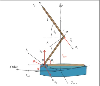
In Fig. 1, x, y, and z are the roll, pitch, and yaw axes, respectively; xi, yi, and zi (i = 1, 2) are the robotic manipulators’ arms axis; qi (i = 1, 2) are the degrees-of-freedom (DOFs) of the arms; φb is the rotational DOF of the manipulator; stands for the Earth; roll, pitch, and yaw are the axes for the attitude representation in the local vertical/local horizontal (LVLH) frame.
For the generalized coordinates, the Lagrange’s formula is:
Figure 1. Physical model to represent a spacecraft containing a robotic manipulator on its structure.
x1
x2
z2
z1
y2
y1
xroll
ypitch Orbit
zb l
l
zy2w
θ θ1
θ2 θ2
For this study only the gravity-gradient torque has been considered as external perturbation. his torque is derived from the gravitational potential energy (for the first order approximation), and the detailed derivation can be seen in Kaplan (1976). he Lagrangian formulation for quasi-coordinates yields the Euler’s modiied equations including the coupling of the spacecrat rotational motion with the arms motion. he Lagrange’s formula for generalized coordinates yields the robotic manipulator equations of motion. he Lagrange’s formula for quasi-coordinates is:
where:
yields the angular momentum vector; [ῶ] is a skew symmetric matrix in the components of the angular velocity vector (ω); T is the kinetic energy; {τg} are {τc} the external and the control torque vectors, respectively.
where:
L is the Lagrangian function; qi (i = 1, 2, 3), q3 = φ,are the DOFs associated with each link of the robot manipulator; Qqi
are the generalized forces.
The Lagrangian function is given by T-V (kinetic and potential energy, respectively). Eventually, L = T, when no potential energy is considered in the problem. In this paper only the kinetic energy T appears in the Lagrangian formulation.
he kinetic energy for the system is given by:
where:
[Jp] and [Ili] are the platform inertia matrices associated with the rotational motion (of the complete system) and the arms, respectively; [Θi] is the transformation matrix relating the satellite frame (roll, pitch, and yaw axes) to those of the links. [JT] is function of θ1, θ2, and θ3 (θ3 = φ) considering the moments of inertia of the manipulator links, written in the satellite frame. The varying part of the inertia matrix is the second parcel in the right side of Eq. 1. This is to say that as the manipulator links move the total inertia matrix varies.
It varies with qi, i = 1, 2, 3. So the matrices [Θ1], [Θ2], and [Θ3] are function of θ1, θ2, and θ3. The third parcel on the right-hand side of the kinetic energy expression represents the crossing terms, and the expression is a function of the satellite and links angular rates, as well as the angles θ1, θ2, and θ3. The coupled terms may be verified in Eqs. 4 to 8.
he kinematics equations considering the linear system (attitude small angles) can be written as (Wie 1998):
(1)
(4) (2)
where:
n is the orbital rate, constant for circular orbit; s and c mean sine and cosine, respectively; θ, ϕ, and Ψ are the pitch, roll, and yaw angles (attitude angles).
The kinematics differential equations for the orbiting spacecrat is then:
moments of inertia in their respective axes. he moments of inertia around the links longitudinal axes were neglected;
uθ1 = Iz12θi, i = 1, 2 are the control torque vector components applied at each joint of the robot links, along z1 and z2 axes; is a product of inertia appearing when projecting the moments of inertia of the arms on the satellite axes (function of the angles θi);
uφ = Izφ is the torque applied in the base of the robotic manipulator links (rotational joint about zb axis). his torque enters into the right side of Eq. 9; τm12 is the torque magnitude of the link acting on the platform; φb is the angular position of the manipulator rotational joint as shown in Fig. 1. his DOF was not considered in the computer simulation; ωx, ωy, and ωz are the components of the satellite angular velocity vector around the roll, pitch, and yaw axes; ω is function of the attitude angles and rates ϕ, θ, ψ, ϕ, θ, ψ (Kaplan 1976); τx, τy, and τz are the components of the gravity-gradient torque. For roll, pitch, and yaw, as deined in this study, the gravity-gradient torque vector can be written as (Wie 1998):
The Euler modified equations of motion are given by Eq. 1 and can be written as:
where:
Jtx,Jyt and Jzt are total moments of inertia for the complete system (satellite plus the manipulator). Note that these moments of inertia are not constant for they depend on the manipulator arms position θ1 and θ2as well as φ; Iy1, Iy2, Iz1, Iz2 are the arms
he linear system equations can be obtained by replacing the linear kinematics equations in the Euler modiied equations (Eqs. 7 – 9) and taking the liner terms in Eqs. 10 and 11. he linear kinematics equations are obtained from Eqs. 5 and 6:
or
he linear expression for the gravity-gradient torque is obtained from Eq. 13 as:
(5)
(6)
(13)
(14)
(15) (7)
(8)
(9)
(10)
(11)
(12)
‥
‥
. . .
THE ATTITUDE CONTROL TECHNIQUE
he LQR is used for the spacecrat attitude control. No control is imposed to the robotic manipulator arms. The arms are only commanded to deploy/retract and rotate. he objective is to actively control the spacecrat attitude while the robotic manipulator is operating and then analyze the impact of arms motion on the control efort. Two diferent versions of mathematical models were used during the simulations. One version in which the deployment/retraction of the arms are not conigured to passively cancel the reactions on the platform and the other in which the form of the arms deployment/retraction cancels the reactions on the platform. In such coniguration the motion of the arms (when deploying/retracting) does not afect the platform motion. To apply the LQR technique the system equations are linearized about the equilibrium coniguration (attitude angles equal to zero). To implement this technique the linear equations are written in the state form as:
For the sake of the computer simulation, φb (the DOF for the irst link of the manipulator — see Fig. 1) was not considered since it plays a role similar to a reaction wheel mounted on the platform and is always under the spacecrat control subsystem. he state matrix is given by:
where:
x is state vector; u is the state feedback control law resulting
from the performance index optimization (cost function). Mathematically the control law is written as:
and it minimizes the cost function:
where:
K is the gain matrix; the matrices Q and R are arbitrary weight matrices associated with the state and the control input, respectively.
he state vector x is deined as:
where:
Z = 5 × 5 null matrix; I = 5 × 5 identity matrix; and
he inertia properties in function of qi are the moments of inertia of the manipulator links written in the satellite frame.
In spite of being arbitrary matrices, Qmust be a positive semi-deinite state matrix and R must be positive deinite witting matrix. Matrices A and B are the plant and input matrices. he control input matrices R and Q are arbitrary. he state matrix
Q is 10 × 10 and diagonal. All the elements were chosen to equal to 1, except the elements Q(4,4) = Q(9,9) = 1e+4. he input matrix R is 4 × 4, and all the elements are 1e+3, except R(4,4) = 1e–9.
he LQR technique requires the solution of the Riccati algebraic equation given by:
(16)
(20)
(21)
(22)
(23)
(24) (17)
(18)
(19)
where:
P is the Riccati matrix.
.
x =
A =
J =
C1 =
hardware and sotware that execute fundamental tasks planned for the experiment. It generates a 3-D image of objects in its ield of view. Furthermore, the Kinect have also a stereo microphone to allow conversations and voice commands. It is provided with an infrared light source, 3-D depth camera, and a RGB camera. he robotic manipulator used in this experiment is an open development as an open-hardware project (http://www.instructables. com/id/Pocket-Sized-Robot-Arm-meArm-V04/). Figure 5 shows the communication hardware. The user sends the commands to the Arduino by using a computer equipped with the Bluetooth technology. he four servos receive the user commands through he plant matrix involves the non-constant inertia matrix
(see Eq. 4) and must be solved at each step of integration. he diferential equations representing the dynamics of a spacecrat like a robotic manipulator are characterized by an inertia matrix that varies with respect to time. he motion of the arm moves the link masses during the robotic operation, changing the moments and product of inertia of the whole space vehicle. he control technique involves working with an inertia matrix that must be updated at each step of integration. he block diagram shown in Fig. 2 presents this important feature of this research. In Fig. 2, u(t) is the state feedback control, e(t) refers to the error given by ref(t) − xout (the state output) to provide the error, and t is the time.
he output returns to the dynamics model updating the inertia matrix and also to the reference for the evaluation of the error.
Figure 2. Control block diagram.
Control
(t)
Dynamics model (t) e (t)
+–
ref u (t)
xout xout xout
Υ
LAB EXPERIMENT
he planned experiment infrastructure consists of glass table, two floating robotic manipulators, a laptop, and the Kinect sensor, as shown in Fig. 3.
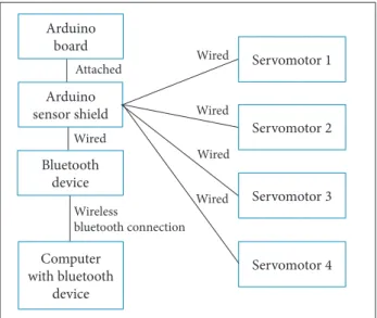
he mathematical model presented in this paper did not consider the DOF of the robotic manipulator grasping hand. An intelligent sensor (Kinect) is planned to track the manipulators motions on the table and is part of a communication subsystem to receive data from the sensor as well as to issue commands to the robot. This communication subsystem consists of a laptop, the Bluetooth technology and Arduinos. he complete system is human-operated and puts the complete system in the category of telerobots. Figures 4, 5, and 6 show the Kinect and the manipulator hardware communication coniguration. he Kinect is a device of sensing movements developed by Microsot® for the Xbox 360 console. It is equipped with a
camera system that allows the user to control and interact with the console without having to touch a game controller, but just using gestures or voice commands. his device is powered by both
Figure 3. Glass table, robotic manipulator, a target, Kinect sensor in a bar over the table, and a laptop.
Figure 4. Kinect sensor to track the motion of the robotic manipulator on the glass table.
Figure 5. Experiment communication system diagram. Arduino
board
Servomotor 1 Wired
Wired
Wired
Wired Wired
Wireless
bluetooth connection Attached
Servomotor 2
Servomotor 3
Servomotor 4 Arduino
sensor shield
Bluetooth device
Computer with bluetooth
the interface with one of the Arduinos. hese are connected by wire while the Bluetooth is a wireless-communication technology.
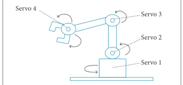
he DOFs of the manipulator are a rotation on its own base — two angular DOFs related to the other two link joints and the hand motion as shown in Fig. 6. he complete problem involves one more DOF related to the platform response to the robotic manipulator motion. In this paper an ice platform is used instead of a loating system (till in development).
Figure 7 shows the real robotic manipulator used in the lab experiment and the associated hardware. he measurements of the reactive linear efects of the manipulator were computed by using a camera to record the motion. he video was then treated to obtain the reaction efects of the manipulator motion on the non-inertial platform. he same procedure was used for the computation of the rotational efect of the links motion on the platform. Figure 8 illustrates the experiment assemblage to record the video.
For future experiments the manipulator platform is planned to use a compressed air system so as to allow the robot to loat on a thin shell of air. However, in this very irst prototype, ice platforms are used to represent the non-inertial base as proposed in the scope of this paper. he experiments being conducted in the lab aim to analyze the impact of the robotic arms on the platform rotational and translational motions. For this study
Response of the ice base to the montion
of the robotic manipulator arms 0.4
0.2
0
–0.2
0 5 10 15
Measurement points
D
is
ta
n
ce
[
m
m
]
20 25 30
–0.4
Figure 7. The robotic manipulator and the associated hardware that were assembled on an ice platform.
Figure 8. assemblage of the experiment to record and measure the ice platform response to the robotic manipulator motion.
the Kinect was not used. It will be used in future experiments with air-supported manipulators. Instead of using Kinect the motion was recorded by using a camera. hen the Kinovea sotware (www.sotware.informer.com) has been used to process the images, generate tables and then the graphics. Figure 9 illustrates the response of the ice platform to the motion of the robotic links (deployment/retraction of the links).
he experiments conirmed that the ice low friction allows the platform to move in response to the robotic manipulator link motions. The robotic manipulator shown in Fig. 7 was not designed so as to cancel the reactions on the ice platform passively.
Figure 6. DOFs of the robotic manipulator on the platform. Servo 4
Servo 3
Servo 2
Servo 1
Figure 9. Motion of the ice platform in response to the robotic manipulator motion.
SIMULATIONS, RESULTS, AND
DISCUSSION
he mathematical model given by Eqs. 6 to 11 has been simulated through computer by considering two scenarios. One in which the robotic manipulator is not working (arms retracted). he other in which the arm is being deployed from a position 0° to 180o. In this case the arm deployment Arduino board
Bluetooth device Voltage regulator
Battery Servo 2
Servo 3
Servo 4
Initial parameters Initial values Units
Jtx0 7.5 kgm2
Jty0 7.7 kgm2
Jtz0 8.0 kgm2
Jtxz0 0.035 kgm2
θ10 0; 180 Degrees
θ20 0; 180 Degrees
Roll 0; 5 Degrees
Pitch 0; 5 Degrees
Yaw 0; 6 Degrees
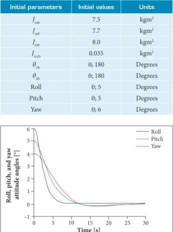
Table 1. Data used for the computer simulations.
Figure 10. attitude control by considering the robot manipulator out of work.
Figure 12. attitude control by considering the robotic manipulator working.
Figure 11. Control effort associated with the case shown in Fig. 10. 0 –1 0 1 2 3 4 5 6
5 10 15
R o ll , p it ch, a nd ya w a tt it u d e a n g les [°]
20 25 30
Roll Pitch Yaw Time [s] 0 –1 0 1 2 3 4 5 6
10 20 30 40 50 60 70
A tt it u d e a n g les [°] 80 Roll Pitch Yaw Time [s] 0 –0.12 –0.1 –0.08 –0.04 –0.05 –0.02 0 0.04 0.02 0.06
5 10 15
C o n tr o l e ff o rt [N m]
20 25 30
u3 (Effort, roll) u4 (Effort, pitch) u5 (Effort, yaw)
Time [s]
configuration does not cancel the reaction, and the base moves in response to the arms retraction. he objective is to analyze the control eforts to keep the satellite attitude within the prescribed.
he data used for the simulation are shown in Table 1, in which the symbols in the irst to the fourth line are the three initial moments and the product of inertia, respectively, Jtx0, Jty0, Jtz0, and Jtxz0 ; θ10and θ20 are the initial angles for the robotic manipulator links.
Figures 10 and 11 show the attitude control and the associated control efort for the satellite with the robotic manipulator of. Figures 12 and 13 show the attitude control and the control eforts by considering the robotic manipulator working, that is, with the manipulator moving. From results shown in Fig. 13, it is clear that the associated control efort is larger by approximately one order compared to the case when the robotic manipulator arms are not moving (Fig. 10). Actually it was expected that the control efort to keep the platform stabilized during the action of the robotic manipulator arms would increase. Note that the
maximum control efort to control the attitude for the case the arms were not moving is 0.06 Nm while for the case in which the arms were moving is 0.36 Nm. Another comment is that the time required to take the spacecrat attitude to the prescribed values (roll, pitch, and yaw equal to zero) is larger for the case when the robotic manipulator is working.
Figure 13. Control effort associated with the case shown in Fig. 12. 0 –0.15 –0.1 0 –0.05 0.05 0.15 0.1 0.2 0.3 0.25 0.35
10 20 30 40 50 60 70
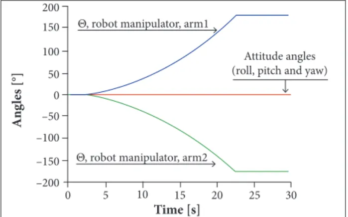
Figure 14 shows the scenario in which the link motions cancel the reactions on the platform. he procedure to obtain the result was as follows: the attitude was set at zero positions in roll, pitch, and yaw. hen the operation to move the arms from zero position to about 180° was performed. he irst manipulator link moves in counterclockwise direction while the second one moves in the clockwise direction, with synchronized motion. he result conirms the platform stability in the absence of any external perturbation. his approach is passive in the sense that no control action is needed to compensate the efect of the reaction torque on the robot base since that reaction is eliminated by the synchronized and reverse motion of the manipulator links.
Figure 14. Result for the scenario in which the motion of the arms cancels the reactions on the platform.
0 –200 –150 –100 –50 0 50 100 150 200
5 10 15
A
n
g
les [°]
20 25 30
Time [s] Θ, robot manipulator, arm1
Attitude angles (roll, pitch and yaw)
Θ, robot manipulator, arm2
on a non-ixed base. An experiment at the SRL laboratory (Divisão de Mecânica Aeronáutica, Instituto Tecnológico de Aeronáutica) was conducted to analyze the dynamics of a robotic manipulator assembled on an ice platform aiming the analysis of the ice platform response to the motion of the robotic manipulator arms. A mathematical model for a spacecrat like robotic manipulator was developed for the sake of attitude dynamics simulations. he goal is the study of the motion impact of the robotic manipulator arms on the attitude control efort and on the required time to take small attitude angles to zero. he results for the case when the robotic arms are moving/not moving were compared in the analysis. hrough simulations it was veriied that the control efort increases for the case when the robotic manipulator arms are moving. Also it was veriied that the required time to take satellite attitude to zero increases for the same case. he simulations also focused on the case where the arms motions were synchronized and in opposite directions so as to cancel the torque reactions on the manipulator platform. The simulations results showed that the attitude is not afected by the motion of the robotic manipulator arms in this case.
ACKNOWLEDGEMENTS
To the Institutos Nacionais de Ciência e Tecnologia (INCT) for Space Studies, Coordenação de Aperfeiçoamento de Pessoal de Nível Superior (CAPES), Instituto Tecnológico de Aeronáutica (ITA), and Departamento de Computação, Pontifícia Universidade Católica de São Paulo (PUC-SP) for the support to this research.
REFERENCES
alexander H, Cannon R (1987) Experiments on the control of a satellite manipulator. Proceedings of the american Control Conference; Seattle, USa.
arantes Jr G (2011) Rendezvous with a non-cooperating target (PhD thesis). bremen: International University of bremen.
Da Fonseca IM (1998) Integrated structural/control optimization of a large space structure with articulation subject to the gravity-gradient torque. São José dos Campos: Instituto Tecnológico de aeronáutica.
Dubowsky S, Papadopoulos E (1993) The kinematics, dynamics, and control of free-lying and free-loating space robotics systems. IEEE Trans Robot autom 9(5):531-543. doi: 10.1109/70.258046
Goddard Jr JS (1997) Pose and motion estimation from vision
using dual quaternion-based extended Kalman iltering (PhD thesis). Knoxville: The University of Tennessee.
Kaplan MH (1976) Modern spacecraft dynamics & control. New York: John Willey & Sons.
Kawano I, Mokuno M, Horiguchi H, Kibe K (1994) In-orbit demonstration of an unmanned automatic rendezvous and docking system by the Japanese Engineering Test Satellite ETSVII. Proceedings of the aIaa-94-3648-CP; Scottsdale, USa.
Kawano I, Mokuno M, Kasai T, Suzuki T (2001) Result of autonomous rendezvous docking experiment of engineering test satellite – VII. J Spacecraft Rockets 38(1):105-111. doi: 10.2514/2.3661
Kawano I, Mokuno M, Toru K, Takashi S (1998) First result of
CONCLUSION
autonomous rendezvous docking experiments on NaSDa’s ETS-VII satellite. Proceedings of the 49th International astronautical Congress. IaF-98-a3.09; Melbourne, australia.
Kawano I, Wakabayashi Y, Kasai T, Suzuki T (1989) In-orbit demonstration concept for the space platform in NaSDa – rendezvous docking system. Proceedings of the International astronautical Federation. IaF-89-017; Malaga, Spain.
longman RW (1994) a tutorial overview of the dynamics and control of satellite-mounted robots. In: Skaar S, Ruoff CF, editors. Teleoperation and robotics in space. Progress in astronautics and aeronautics. vol. 161. Washington: aIaa. p. 237-258.
Meirovitch l (1970) Methods of analytical dynamics. New York: McGraw-Hill.
Mokuno M, Kawano I, Hiroshi H, Kibe K (1995) Development of the ETS-VII RVD system by the Japanese Engineering Test Satellite ETS-VII. Proceedings of the aIaa-95-3357; baltimore, USa.
Mukherjee R, Zurowski M (1994) Reorientation of a structure in space using a three-link rigid manipulator. J Guid Contr Dynam 17(4):840-847. doi: 10.2514/3.21274
National aeronautics and Space administration (2005) Press kit;
[accessed 2007 May 5]. www.nasa.gov/news/0600515_dart_ mishap_summary.html
Pedersen l, lortenkamp D, Wettergreen D, Nourbakhsh I, Smith T (2004) NaSa Exploration Team (NEXT) Space Robotics Technology assessment Report. NaSa/TM-2004.
Qureshi F, Terzopoulos D (2008) Intelligent perception and control for space robotics. Mach Vis appl 19(3):141-161. doi: 10.1007/ s00138-007-0085-z
Skaar Sb, Ruoff CF (1994) Teleoperation and robotics in space. Progr astronaut aeronaut 61:443-489. doi: 10.2514/4.866333
Umetani Y, Yoshida Ka (1987) Continuous path control of space manipulators mounted on OMV. acta astronaut 15(12):981-986. doi: 10.1016/0094-5765(87)90022-1
Vafa Z, Dubowsky S (1987) On the dynamics of manipulators in space using the virtual manipulator approach. Proceedings of the IEEE International Conference on Robotics and automation; San Francisco, USa.
Wie b (1998) Space vehicle dynamics and control. aIaa Education Series. Reston: aIaa.