Abstract—This study simulated the copper nanocutting with a rigid body tool and elastic body tool and then analyzed the workpiece and tool temperature, stress distribution, and surface quality during cutting using molecular dynamics. After simulations, a diamond rigid tool with both a completely sharp and 2.7 nm nose radiuse produce a shear plane during cutting. However, the shear zone for the sharp tool was thinner than that of the tool with the nose, and chips piles near the nose were chaotic. The distribution of equivalent stress was greatest at the shear zone by rigid body tool or by elastic body tool cutting. When cutting with the elastic body tool, the stress distribution of tool was greatest at the nose. The chip temperature was highest near the central rake and nose. The workpiece temperature when the elastic body tool cutting was lower; the temperature in the nose and rake plane is the highest, the more away from the nose, the lower the temperature. The fractal dimensions of the machined surface after rigid body tool cutting was 2.11, while the fractal dimension after elastic body tool cutting was 2.13. Therefore, the machined surface was more irregular after elastic body tool nanocutting.
Index Terms—Molecular Dynamics, Nano-cutting, Heat transfer, Single crystal copper, Elastic body tool
I. INTRODUCTION
N order to understand the properties and mechanisms of nano-scale processing, theoretical analysis is necessary. Nano-scale processing involves changes in only a few atomic layers at the surface. At such a small governing length scale, the continuum representation of the problem becomes questionable [1]. Accordingly, the approach of the molecular dynamics (MD) model is undoubtedly needed to trace the behavior of atoms with the short-range interaction during short-time scale.
MD simulation studies, in general, were initiated in the late 1950’s by Alder and Wainwright [2, 3] in the field of statistical mechanics. Based on the MD simulation, Maekawa and Itoh [4] and Zhang and Tanaka [5] conducted MD analyses of processing and friction characteristics of ultra-precise cutting on the atomic scale. These analyses were based on a two-dimensional (2D) model to reduce the calculation time. 3D MD analysis is required to provide a
This work gratefully acknowledges the financial support of the National Science Council, Taiwan through contract No. NSC 98-2221-E-236-007.
Professor Jen-Ching Huang is with Department of Mechanical Engineering at Tungnan University, New Taipei City, Taiwan, (corresponding author to provide phone: +886-2-86625834; fax: +886-2-86625919; e-mail: jc-huang@mail.tnu.edu.tw).
deep insight into nano cutting. Isono and Tanaka [6] carried out a 3D MD analysis of the effects of temperature, machinability and interatomic force on nickel metal.
Chandrasekaran et al. [7] investigated a method termed the Length Restricted Molecular Dynamics (LRMD) simulation to reduce the computational time and at the same time reduce the memory requirements significantly. Komanduri et al. [8] reported MD simulation studies of machining with large negative rake angle tools to simulate grinding and compared the simulation results with the experimental results resulting in good agreement. Komanduri et al. [9] also investigated the effect of tool geometry with tools of different edge radii relative to the depth of cut in nano-scale cutting.
Lin and Huang [10] directly regarding the atom as a node, and the lattice as an element, Lin and Huang suggested a way that combined FEM shape function concept and MD techniques to calculate the equivalent stress and equivalent strain of single crystal copper caused by three dimensional nano-scale cutting.
Lin and Huang [11] proposes a method that combines molecular dynamics with finite element deformation model (MDFM) to calculate the various axial stress and strain of single crystal nickel that occur during nano-scale cutting by conical tool. They also employs rigid boundary layer interface force (RIF) model developed by Lin and Huang [12] to calculate the cutting force of single crystal nickel during nano cutting.
Lin and Huang [13] uses molecular dynamics to simulate the nanoscale cutting of a Cu single crystal by a conical diamond tool. Actual nanoscale straight-line cutting experiments are performed and the experimental results compared with the simulation results. The heaping of copper atoms is qualitatively quite consistent with the simulation result. They also proposes a Nanoscale Contact Pressure Factor (NCP Factor) that is applicable to the probes at different tip radii. An estimation model model of the cutting force for nanoscale cutting is established. This model can estimate the cutting force during actual nanoscale cutting. Lin and Huang [14] uses a method that combines molecular dynamics with finite element deformation model (MDFM) to calculate the stress and strain of single crystal copper that occur during nano-scale orthogonal cutting. They finds that it has only minor influence for the different cutting speeds on the distribution of the strain and stress at the contact area between the cutting chip and rigid tool during steady cutting state.
From the above literature, most of the literatures used in the nanocutting simulations use a rigid body tool to cut
The Study on the Nanocutting by Rigid Body
Tool and Elastic Body Tool Using Molecular
Dynamics Simulations
Jen-Ching Huang
material in a vacuum environment. Most of the literatures have rarely focused on temperature fields created by cutting. By considering the tool as a rigid body, it has been unable to analyze the temperature change and wear of tool. For these reasons, this study constructed a molecular dynamics nanocutting simulation that considered the heat transfer of elastic body tool to study the cutting conditions for single crystal copper material under different cutting parameters and to evaluate the temperature of the workpiece and the tool, stress distribution, and machined surface quality during cutting.
II. MOLECULAR DYNAMIC SIMULATION OF NANOCUTTING A. Nano-cutting Simulation Model
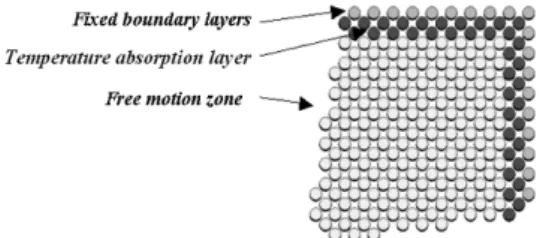
In this study, a workpiece and a tool are assumed to consist respectively of single crystal copper and rigid diamond, as shown in Fig. 1 and Table I. The work material in the MD simulation is divided into three different zones, namely the free motion zone, temperature controlled layer and the fixed boundary layer. To simulate the nano-scale cutting of the (001) plane of copper, we utilize a copper slab of dimensions 20a × 10a × 10a, consisting of 8000 atoms, where a is the lattice constant of copper (3.61 Å).
The boundary conditions of nano-scale cutting simulation included the three layers of atoms in the y-z faces (left side of the work material) and the lower x-y plane (bottom of the work material) being kept fixed in this study. All other atoms are allowed to move with the MD algorithm. A layer of atoms at the free motion zone and close to the fixed boundary layer are considered as thermostat atoms. In another word, the layer of atoms is considered as a temperature controlled layer and used to absorb the heat towards primary cells.
When the MD simulation of nanoscale cutting is performed using a tool of a particular tip radius, a greater cutting depth corresponds to a larger workpiece: many the
calculation time in the simulation increases substantially with the number of atoms in the workpiece. Zhang and Tanaka [5] performed an MD simulation of nanoscale cutting and determined that if the ratio of cutting depth to tip radius is greater than or equal to 0.09, then the cutting is nanoscale cutting. In this study, the tip radius of the probe is 2.7 nm. Therefore, whenever the cutting depth is greater than or equal to 0.243 nm, cutting is in the cutting regime. In the simulation, the cutting depths are 0.25nm, 0.35nm, 0.45nm, 0.55nm and 0.65nm. Thus, not only can the cutting can be studied, but also the calculation time is acceptable.
This study used two types of tools in its simulation: one rigid body diamond tool and one elastic body diamond tool. In typical metal machining conditions, a soft copper surface is machined by a considerably harder tool or abrasive element. The hardness of diamond is 10, whereas copper is considerably softer (hardness < 5) depending on the surface preparation [15]. Under such conditions it is a good approximation to consider the tool as a rigid body. The schematic illustration of a rigid body tool is shown as Fig. 2.
However, it is impossible to calculate tool temperature and stress using a rigid body tool. A real diamond tool is a brittle material, but before it splits, it will always become elastic. For this reason, real diamond tools can be considered elastic. Therefore, to understand the distribution of temperature and stress on a tool during cutting, the other type of tool used in this study was elastic. Besides elastic body tools considering the calculated applied force between molecules, the greatest differences between elastic body tools and rigid body tools are the free motion zone and the temperature absorption layers in elastic body tools. The schematic illustration of an elastic body tool is shown as Fig. 3.
Fig. 2. Illustration of rigid body tool (a) With perfect sharpen tip (b) With nose radius
TABLEI
COMPUTATIONAL PARAMETERS USED IN MDSIMULATION OF NANO-SCALE
CUTTING OF COPPER SINGLE CRYSTAL
Configuration Nano cutting
Copper (Work material ) 20a×10a×10a, atoms: 8000
Tool
Rigid body diamond (with perfect sharpen tip and 2.7 nm nose radius), Elastic body diamond with 2.7 nm nose
radius
Tool rake angle 10°
Tool clearance angle 8°
Depth of cut 0.25nm, 0.35nm, 0.45nm, 0.55nm, 0.65nm
Cutting speed 200 m/sec
Bulk temperature 293 K
B. MD Simulation
In this study, the Gear’s predictor-corrector method [16] is adopted to calculate the positions, velocities and accelerations of atoms under displacement condition. The both Verlet’s neighbor lists [16] and truncated radius method [16] are employed to reduce the calculation requirements. Firstly, the relaxation phase was completed within 20000 time steps by controlling the bulk temperature at a 293K using an NVT ensemble [16]. And the nano-scale cutting was simulated by displacing the diamond tool with small distance (interval) towards the negative direction of X-axis in each time step, and followed by relaxation for 500 MD steps. Further details of MD simulation procedure are given in [16].
In this study, the potentials applied throughout the entire simulation process were divided into interaction within the diamond tool, within the copper workpiece, and between the diamond tool and the copper material. Because the bonded carbon atoms in the tool were covalent bonds, and because Tersoff potentials [17] in covalent bond potential simulations are extremely accurate regarding the physical properties of the diamond, this study used Tersoff potentials in the tool. The Morse potential [18] function was used to describe the interaction between the carbon atoms and copper atoms. The tight-binding second moment approximation (TB-SMA) [19] was used to describe the copper atoms.
III. THE CALCULATION OF TEMPERATURE,ATOMISTIC
STRESS AND FRACTAL DIMENSION A. Calculation of Temperature
When cutting duration, heat must be produce at the tool, the workpiece, and the interface between the tool and the workpiece, and nanocutting is no exception. To simulate the heat conduction at these three points, this study regarded the layer of atoms between the free motion zone and the fixed rigid boundary of the copper workpiece and the elastic body tool as thermostat atoms. In other words, this layer of atoms was established as the temperature absorption layer.
At nano-scale cutting simulation, when temperature of the temperature absorption layer is higher than the preset one of 293K, velocity rescaling method as shown in Equation (1) [16] will be used to control the temperature of the temperature absorption layer and absorb the heat towards primary cells (control volume).
Converting the average kinetic energy into a temperature as shown in Equation (2) [16] does conversion of temperature for thermostat atoms. Successful application of Equation (3) can be found in prior works such as Lin and Huang [11-14].
A D i new i
T T
v v,
(1)
i i i A
N
T v v
3 1
(2) Where vi,new is the velocity of the particle i after correction. TD and TA are the desired temperature and actual temperature of system, respectively. N is the total number of temperature-controlled layers.
To determine the temperature distribution of the tool and the workpiece during nanocutting, this study converted a single atom’s kinetic energy into its atomic temperature (Ti) as shown in Equation 3. Utilizing the average interpolation numerical method to average the regions of atomic temperature, we further determined the regional temperature field distribution during nanocutting.
( 3) B. Calculation of Atomistic Stress
During nanocutting, the stress distribution of the tool and the copper workpiece is a vital information. Stress calculations on a nanoscale are vastly different from the calculations on a macroscale. For this reason, this study used BDT stress to evaluate the stress of the tool and the copper workpiece during nanocutting [20].
BDT stress, proposed by Basinski, Duesberry, and Taylor [20], is a method for calculating atomic-level stress. Under the assumption that the material is homogenous, this method calculates the stress for each atom. The calculation formula as Equation (4).
(4 ) Where the stress on each atom i is , and where Vi is the regional particle volume around atom i. The regional particle volume is calculated using equations presented by Srolovitz et al. [21], as displayed in Equation (5) and Equation (6).
3
3 4
i
i a
V
(5) where Vi is the regional particle volume to particle i. ai represents regional particle radius and given by Equation (6)
2
1
2 ij ij i
r r a
( 6) where rij is the distance between Number j atom and Number i atom.
C. Calculation of Fractal Dimension
This paper uses fractal theory to analyze the machined surface and to investigate the effect of different types of tools and nose radii on the quality of the machined surface appearance. Dubuc [22] and Hasgawa [23] respectively compared several calculation methods of fractal dimension.
In the comparison, it is found that the dimension simulated from the surface by variation method is closest to the theoretical dimension, and appears in linear distribution. From here, it can be known that the calculation of fractal dimension by variation method can get the smallest error. Next it introduces the variation method [22] employed in the paper.
The application of variation method to R3 (3D) for the
calculation of fractal dimension [24] is:
1, 1
2, 2
sup ) , ,
(x y f x y f x y
V (7)
1, 2, 1, 2
max x x x x y y y y (8) where Cutting factor: 22 (the basal area of the small
cut cube is 42)
sup: supremum, or the least upper bound
Then, fractal dimension can be acquired by using the following equation:
log
, , log 3 lim
1
0 1
0
0
dxdy y x V D
(9) Fractal dimension can also be acquired through the slopes of the figures, log1 and log( , )
2 1
0
V x dx.
IV. RESULT AND DISCUSSION
A. The effect of Cutting Depth
The simulation results for rigid body tools using a cutting speed of 200 m/s on the 5000th step at cutting depths of 0.25 nm, 0.35 nm, 0.45 nm, 0.55 nm, and 0.65 nm are displayed in Figure 4. From Figure 4, due to the tool’s action, cutting chip is heaped around the single crystal copper workpiece. With the increase of cutting travel distance, the height of the heap of cutting chip is gradually raised. Additionally, a clear shear plane is also observable.
The volume of material removed is related to the cutting depth. Figure 4 shows that the deeper the cut, the larger the area of distortion under the tool in the copper workpiece. Furthermore, the machined surface under the flank plane is
attracted by the atoms in the tool and moves upward. B. The effect of Nose Radius
Figures 5 and 6 show the results of a completely sharp rigid body tool and a rigid body tool with nose cutting at a depth of 0.25 nm and a speed of 200 m/s. Figure 5 reveals that a completely sharp rigid body tool already produced a pile of chips during the early cutting stage and possessed a clear shear plane. Figure 6 indicates that when a rigid body tool with nose is used, the copper workpiece by the compression effect of the nose during the early stages of cutting. Additionally, once the tool has cut to the 5000th step, its shear zone is larger and distributed around the nose. Both figures 5 and 6 reveal that the types of chip piles created by nanocutting with a nosed tool and a completely sharp tool are entirely different.
Clear shear planes exist when nanocutting with either a completely sharp or a nosed diamond rigid body tool. However, the shear zone of the completely sharp tool is thinner, while the shear zone of the nosed tool is larger and chip atoms pile near the nose is somewhat chaotic.
C. The equivalent Stress Distribution and Temperature Distribution
The results of a nosed rigid body tool and a nosed elastic body tool cutting to the 10,000th step at a depth of 0.25 nm and a speed of 200 m/s are shown as Figures 7 and 8.
From Figure 7(a), when cutting with the rigid body tool, the cutting action on the chips produced a clear shear zone on plane 111. Figure 8(b) shows that the equivalent stress was greatest in the shear zone, and that residual stress occurred on the machined surface.
Figure 8(a) indicates that when cutting with the elastic body tool, the tool itself was still distorted slightly as the greatest equivalent stress is placed on the tool nose. Additionally, the stress distribution on the chips differed from that of cutting with a rigid body tool. According to Figure 8(b), while the area of greatest equivalent stress distribution on the workpiece for both the rigid and elastic
Fig. 6. Nanocutting with a nosed rigid body tool (a) 2000 th step (b) 5000 th step
Fig. 5. Nanocutting with a completely sharp rigid body tool (a) 2000th step (b) 5000th step
body tool was the shear zone, the distribution was wider with an elastic body tool. Identical to the effect of a rigid body tool, residual stress occurred on the machined surface.
The temperature distribution for a nosed rigid body tool and a nosed elastic body tool cutting to the 10,000th step at a depth of 0.25 nm and a speed of 200 m/s are shown as Figures
9 and 10.
From Figure 9, when cutting with the rigid body tool, the chip temperature was highest at the central rake plane and on the nose. This indicates that the friction between the chips, the central rake plane, and the nose is relatively great.
Figure 10 reveals that when cutting with the elastic body tool, due to the excellent heat conductivity of the diamond tool, the workpiece temperature was less than cutting with the rigid body tool (Figure 9), and the temperature distribution also differed from Figure 9. The tool temperature was highest at the nose and the rake plane, and decreased further from the nose.
D. The Quality of Machined Surface
This study evaluated the appearance of the machined surface using fractal dimensions to investigate the effect of different tool types and nose radii on the quality of machined surfaces. Figures 11 and 12 show the appearance of the copper workpiece machined surface of a nosed rigid body tool and a nosed elastic body tool cutting to the 10,000th step at a depth of 0.25 nm and a speed of 200 m/s.
After calculations, the fractal dimensions of the machined surface after rigid body tool cutting was around 2.21 while the fractal dimension after elastic body tool cutting was around 2.23. These results indicate that, compared with nanocutting using a rigid body tool, the machined surface after nanocutting using an elastic body tool was relatively complex and irregular. Therefore, different tool types absolutely affect the quality of the machined surface.
Fig. 9. The temperature distribution when cutting to the 1000th step with a nosed rigid body tool
Fig. 10. The temperature distribution when cutting to the 1000th step with a nosed elastic body tool
Fig. 8. The appearance and equivalent stress distribution of workpiece when cutting to the 1000th step with a nosed elastic body tool (a) Appearance of workpiece (b) Equivalent stress distribution of workpiece
V. CONCLUSIONS
This study successfully constructed a molecular dynamic nanocutting analysis model that considered the effect of non-rigid body tools and heat conductivity. Using single crystal diamond as the tool and dividing it into rigid body and elastic body tools, the cutting circumstances of using rigid body and elastic body tools on single crystal copper material under different cutting parameters were investigated. The workpiece and tool temperatures, the stress distribution, and the surface quality were analyzed during cutting.
The results of the simulation indicated that a single crystal diamond rigid tool with both a completely sharp (nose radius of 0) and a 2.7 nm nose radius produce a significant shear plane during cutting. However, the shear zone of the completely sharp tool was thinner than that of the tool with the nose, and chip atoms pile near the nose were chaotic.
When cutting with the rigid body tool, the workpiece equivalent stress distribution was greatest at the shear zone; when cutting with the elastic body tool, it was greatest at the nose. The chip stress distribution also differed when the rigid body tool was used, as the greatest equivalent stress distribution area on the workpiece was also the shear zone, however, the distribution was wider.
When cutting with the rigid body tool, the chip temperature was highest near the central rake and nose. The workpiece temperature when cutting with the elastic body tool is lower than that using the rigid body tool. The tool temperature distribution was highest at the nose and the rake plane, and decreased further from the nose.
The fractal dimensions of the machined surface after rigid body tool cutting was around 2.21 while the fractal dimension after elastic body tool cutting was around 2.23. These results indicate that, compared with nanocutting using a rigid body tool, the machined surface after nanocutting
using an elastic body tool was relatively complex and irregular.
REFERENCES
[1] Y. Y. Ye, R. Biswas, J. R. Morris, A. Bastawros and A. Chandra, “Molecular dynamics simulation of nanoscale machining of copper,”
Nanotechnology, vol. 14, no. 3, pp. 390–396, Feb. 2003.
[2] B. J. Alder, and T. E. Wainwright, “Studies in Molecular Dynamics. I. General Method,”J. Chem. Phys., vol. 31, pp. 459–466, 1959.
[3] B. J. Alder and T. E. Wainright, “Studies in Molecular Dynamics. II: Behaviour of Small Number of Spheres,” J. Chem. Phys., vol. 33, pp.
1439–1451, 1960.
[4] K. Maekawa and A. Itoh,“Friction and tool wear in nano-scale
machining-a molecular dynamics approach,” Wear, vol. 188, pp.
115–122, 1995.
[5] L.C. Zhang and H. Tanaka, “Towards a Deeper Understanding of
Friction and Wear on the Atomic Scale - A Molecular Dynamics Analysis,” Wear, vol. 211, pp. 44–53, 1997.
[6] Y. Isono and T. Tanaka, “Three-dimensional molecular dynamics simulation of atomic scale precision processing using a pin tool,” Int. J.
Ser. A: Mech. Mater. Eng., vol. 40, no. 3, pp. 211–218, 1997.
[7] N. Chandrasekaran, A. Noori Khajavi, L. M. Raff and R. Komanduri, “A New Method for MD Simulation of Nanometric Cutting,” Phil. Mag. B., vol. 77, no. 1, pp. 7–26, 1998.
[8] R. Komanduri, N. Chandrasekaran and L. M. Raff, “Some aspects of machining with negative-rake tools simulating grinding a molecular dynamics simulation approach,” Philos. Mag. B, vol. 79, no. 7, pp.
955-968, 1999.
[9] R. Komanduri, N. Chandrasekaran, and L. M. Raff, “Effect of Tool Geometry in Nanometric Cutting: A Molecular Dynamics Simulation Approach,” Wear, vol. 219, pp. 84-97, 1998.
[10] Z. C. Lin and J. C. Huang, “A nano-orthogonal cutting model based on a modified molecular dynamics technique,” Nanotechnology, vol.15,
pp. 510–519, Feb. 2004.
[11] Z. C. Lin, J. C. Huang and Y. R. Jeng, “3D Nano-scale Cutting Model for Nickel Material,” J. Mater. Process. Tech., vol.192-193, pp. 27–36,
Oct. 2007.
[12] Z. C. Lin and J. C. Huang, “A study on rigid body boundary layer interface force model for stress calculation and stress-strain behaviour of nanoscale uniaxial tension,” Nanotechnology, vol. 15, pp.
1509–1518, Sep. 2004.
[13] Z. C. Lin and J. C. Huang, “The study of estimation method of cutting force for Conical Tool under Nanoscale Depth of Cut by Molecular Dynamics,” Nanotechnology, vol. 19, pp.115701–1-13, Feb. 2008.
[14] Z. C. Lin and J. C. Huang, “The influence of different cutting speeds on the cutting force and strain-stress behaviors of single crystal copper during nano-scale orthogonal cutting,” J. Mater. Process. Tech., vol.
201, pp. 477–482, May 2008.
[15] Handbook of Physics and Chemistry, Boca Raton, FL Chemical
Rubber Company Press, 2002.
[16] J. M. Haile, Molecular Dynamic Simulation: Elementary Methods, John Wiely& Sons, Inc., USA, 1992.
[17] J. Tersoff, “Modeling solid-state chemistry: Interatomic potentials for multicomponent systems,” Phys. Rev. B, vol. 39, pp.5566–5568, 1989.
[18] L. A. Girifalco and V. G. Weizer, “Applaction of the Morse Potential Function to Cubic Metals,”Phys. Rev. vol. 114, pp. 687–690, 1959.
[19] F. Cleri and V. Rosato,“Tight-binding potentials for transition metals and alloys,” Phys. Rev. B, vol. 48, pp. 22–33, 1993.
[20] Z. S. Basinski, M. S. Duesbery and R. Taylor, “Influence of Shear Stress on Screw Dislocations in a Model Sodium Lattice,” Canadian J.
Phys. vol. 49, pp. 2160–2180, 1971.
[21] D. Srolovitz, K. Maeda, V. Vitek and T. Egami, “Structural defects in amorphous solids statistical analysis of a computer model,”Philos.
Mag. A, vol. 44, 847–866, 1981.
[22] B. Dubuc, J. F. Quiniou, C. Roques-Carmes, C. Tricot and S. W. Zucker, “Evaluating the Fractal Dimension of Profiles,” Phys. Rev. A,
vol. 39, pp. 1500–1512, 1989.
[23] M. Hasegawa, J. Liu, K. Okuda and M. Nunobiki, “Calculation of the fractal dimensions of machined surface profiles,” Wear, vol. 192, pp. 40–45, Mar. 1996.
[24] B. Dubuc, S. W. Zucker, Tricot C., J. F. Quiniou and D. Wehbi, “Evaluating the Fractal Dimension of Surfaces,” Proc. R. So. Lond, Se. A, vol. 425, pp. 113–127, 1989.
Fig. 12. The copper workpiece appearance when cutting to the 1000th step with a nosed elastic body tool