18
–
Pulse Converter Using 3/9 Auto-transformer
Ahmad Hoteit1 and Gaitov Hamidovich
Kuban State Technological University Krasnodar, Russia
Abstract
This paper focuses to 3/9 phase auto-transformer with multiple windings per phase is powered a 9-phase AC to DC converter this type of transformer has 40o phase shift between the output voltages, it is supplied from a three phase AC source with star or delta connection, to use this type of transformer in aerospace the operation frequency should be at 400Hz in addition to reduce the current harmonic distortion through a three phase line reactor are connected after three phase AC source in this case the current harmonic distortion decreases to value less than 5% and it can be less than 3% level by using an additional suppression devices (Chokes) at the output of the converter, this autotransformer includes three sections each spaced 120o electrically apart. Each section comprises a main winding and a pair of phase shift windings, it is a main element in 18 pulse converters, the multiphase rectification can be analyzed by using orcad simulation software, and shown the comparisons between the odd phases so that the 9 phases has a lower value of the ripple factor which is 0.763 %.
Keywords: autotransformer, line reactor, chokes, multiphase rectification.
1. Introduction
An autotransformer has only a single winding with two end terminals, and one or more terminals at intermediate tap points. The primary voltage is applied across two of the terminals, and the secondary voltage taken from two terminals, almost always having one terminal in common with the primary voltage. The primary and secondary circuits therefore have a number of windings turns in common. Since the volts-per-turn is the same in both windings, each develops a voltage in proportion to its number of turns. In an autotransformer part of the current flows directly from the input to the output, and only part is transferred inductively, allowing a smaller, lighter, cheaper core to be used as well as requiring only a single winding. One end of the winding is usually connected in common to both the voltage source and the electrical load. The other end of the source and are connected to taps along the winding. Different taps on the winding correspond to
step –down transformer the source is usually connected across the entire winding while the load is connected by a tap across only a portion of the winding. In a step –up transformer, conversely, the load is attached across the full winding while the source is connected to a tap across a portion of the winding. As in a two-winding transformer, the ratio of secondary to primary voltages is equal to the ratio of the number of turns of the winding the connect to. An autotransformer does not provide electrical isolation between its windings as an ordinary transformer does, if the neutral side of the input is not at ground voltage, the neutral side of the output will not be either. A failure of the insulation of the windings of an autotransformer can result in full input voltage applied to the output. Also, a break in the part of the winding that is used as both primary and secondary will result in the transformer acting as an inductor in series with the load. These are important safety considerations when deciding to use an autotransformer in a given application.
Because it requires both fewer windings and a smaller core, an autotransformer for power applications is typically lighter and less costly than a two-winding transformer, up to a voltage ratio of about 3:1 beyond that, a two-winding transformer is usually more economical.
In three phase power transmission applications, autotransformers have the limitations of not suppressing harmonic currents and as acting as another source of ground fault currents. A large three-phase autotransformer may have a “buried” delta winding, not connected to the outside of the tank, to absorb some harmonic currents. For a variable autotransformer intended to conveniently vary the output voltage for a steady AC input voltage. The term is often used to describe similar variable autotransformers made by other makers. To provide very small increments of adjustment, the secondary connection is made through a brush that slides across the winding coils. Variable autotransformers are still used when an undistorted variable voltage sine wave is required.
and it has a 9 phases at the output with multiple windings per phase, and there is a 40o phase shift between them, the boost ratio of this type of autotransformer defined by the ratio of the desired output voltage to the AC source voltage. For example, if the AC source voltage is 110 Volts and the desired output voltage of the transformer is 220 Volts then the boost ratio is 2. But the boost ratio for the applied autotransformer in this paper is 2.5. The system of 18 pulse converter is illustrated in the fig. a and fig. 1-b.
Fig. 1-a: Illustrates of system of 18 pulse converter using auto-transformer without three phase line reactors.
Fig. 1-b: Illustrates of system of 18 pulse converter using auto-transformer with three phase line reactors, they are used to suppress the
current harmonic distortion.
2. Description
The fig. 2 shows the implementation of the multiphase autotransformer so that includes three sections each spaced by 120oeach section contains a main winding, the first main winding should be divided through the center tap into a first turns n1 and the second turns n2, thus the center tap determines the boost ratio through the ratio of the first turns n1 to the total turns of the main winding which is n1 +n2 ,to realize the boost ratio 2.5 the total turns of the first main winding is 1 and the first turns n1 is 0.4 ,and the second turns is 0.6 .For the boost ratio 2 the first turns n1 is equals to the second turns n2 of 0.5, the pair of phase shift windings each have one end connected to the center tap of the main windings. The other end of each phase shift windings 9, 4 is a phase of the autotransformer that is shifted +/-40o electrically from the output end 1 and they have the turns number of n3.The second and third main windings have the same turns number of n1, n2 and n3 as determined in the first main winding, the ratio between the first, second and third number of turns of about 0.4: 0.6: 0.74, respectively .The three phase AC voltage source Vph1, Vph2 and Vph3 are applied to the center tap of each main windings respectively, the fig. 3 shows the winding configuration of the used autotransformer for boost ratio 2.5 . To reduce the current harmonic distortion produced by this transformer will be through a three phase line reactor are connected after three phase AC source in this case the current harmonic distortion decreases to value less than 5% and it can be less than 3% level by using an
additional suppression devices (Chokes) at the output of the converter.
Fig. 2: Illustrates the implementation of the 3/9 auto-transformer.
Fig. 3: Illustrates the winding configuration of the auto-transformer so that the boosting ratio of 2.5, then n1:n2:n3 = 0.4; 0.6; 0.74.
3. Analysis of 18 pulse converter
3.1 Study of the voltages
a- The average output voltage
For the bridge rectifier with m phases, the average output voltage is given as the following:
V
o/p average= 2.( ).V
max.Sin( )
b- The effective output voltage
Let Vo/p effective is the effective voltage at the output of bridge rectifier with m phases then the expression of this voltage is given as the following:
c-The maximum inverse voltage of the diodes (VRWM) The inverse voltage pass through two maximum by a period, for wt= - and wt= +
If VRWM=2Vmax. Cos (π/2m) .Generally we want to choose the diode with a voltage |VRWM |=2Vmax .
3.2 Study of the currents
a- The average output current
The average output current in the load is given as the following:
I
o/p average= 2( ). (
).Sin ( )
b- The effective output current
Let Io/p effective is the effective current in the load. Expression of this voltage is given as the following:
I
o/p eff= 2(
).
c- The average current in the diodes The average current in each diode is:
I
D average= . (
).Sin
During the period of the conduction of the diode the current will be as the following:
I
D max= I
o/p max=I
o/p average3.3 Study of the ripple at the output
Assume the ripple factor is symbolized by Ko and is defined by the following expression:
K
o=
During the period - , + , Vo/pmax = Vmax, Vo/pmin= Vmax. Sin( ) = Vmax. Cos ) then Ko =
This analysis gives Ko = ( ). , with n=m if m is even, and n=2m, if m is odd.
3.4 Applications for 5, 7 and 9 phases
a-
Applications for 5 phases
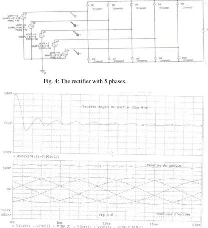
Study of voltages for the rectifier with 5 phases Using the general equations as shown above, where that m = 5 and the Vi/peff = 220V, Vmax = 220 = 311,12V. The results are: Vo/p average = 582 V, Vo/p eff = 583.2V, VRWM = 591,7V.
For the load resistance Rl = 1KΩ. The results are: Io/p average = 0.582 A, Io/p eff = 0.583.2A, ID average = 0.1164A.
The ripple factor for the rectifier with 5 phases The result is Ko = 0.0248 or Ko = 2.48%.
Verification by simulation
The figure (4) represents the rectifier with 5 phases, it is verified by simulation program (Orcad), the results of the input and output voltages are shown by figure (5) and the results of voltage and current in each diode are shown by figure (6).
Fig. 4: The rectifier with 5 phases.
Fig. 6: The results of the input and output currents of the rectifier with 5 phases
b-
Applications for 7 phases
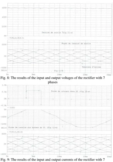
Study of voltages for the rectifier with 7 phases Using the general equations as shown above, where that m=7 and the Vi/peff=220V, Vmax=220 =311,12V. The results are: Vo/p average = 601.5 V, Vo/p eff = 601.85V, VRWM = 606.639V.
Study of the currents for the rectifier with 7 phases For the load resistance Rl = 1KΩ. The results are: Io/p average = 0.6015A, Io/p eff = 0. 60185A, ID average = 0.0859A.
The ripple factor for the rectifier with 7 phases For m = 7 (odd) and n = 2m, n = 14 then the result is Ko = 0.01264 or Ko = 1.26%.
Verification by simulation
The figure (7) represents the rectifier with 7 phases, it is verified by simulation program (orcad), the results of the input and output voltages are shown by figure (8) and the results of voltage and current in each diode are shown by figure (9).
Fig. 7: The rectifier with 7 phases
Figure (9) illustrates the results of the input and output currents of the rectifier with 7 phases
Fig. 8: The results of the input and output voltages of the rectifier with 7 phases
c-
Applications for 9 phases
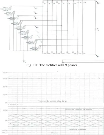
Study of voltages for the rectifier with 9 phases Using the general equations as shown above, where that m = 9 and the Vi/peff = 220V, Vmax = 220 = 311.12V. The results are: Vo/p average = 609.68V, Vo/p eff = 609.79V, VRWM=612.78V.
Study of the currents for the rectifier with 9 phases For the load resistance Rl = 1KΩ. The results are: Io/p average = 0.60968A, Io/p eff = 0. 60979A, IDaverage = 0.0676A.
The ripple factor for the rectifier with 9 phases For m = 9 (odd) and n = 2m, n = 18, then the result is Ko = 0.00764 or Ko = 0.763%.
Verification by simulation
The figure (10) represents the rectifier with 9 phases, it is verified by simulation program (Orcad), the results of the input and output voltages are shown by figure (11) and the results of voltage and current in each diode are shown by figure (12), in addition to that the figure (13) shows the ripple factor in terms of the odd and even phases number, the figure (14) shows the ripple factor in terms of the odd phases number , the figure (15) shows the ripple factor in terms of the even phases number .
Fig. 10: The rectifier with 9 phases.
Fig. 11: The results of the input and output voltages of the rectifier with 9 phases
Fig. 12: The results of the input and output currents of the rectifier with 9 phases
Fig. 13: The ripple factor in terms of the number of phases (odd and even)
Fig. 14: The ripple factor in terms of odd number of phases
3.5- Comparison table
This table represents the more important results for each rectifier, by using the simple effective input voltage as the reference of voltages.
m 3 5 7 9
2.339 2.645 2.734 2.7712
2.377 2.65 2.735 2.7717
F= 1.0165 1.002 1.00058 1.00018
2.4494 2.6895 2.7574 2.7853
1/3 1/5 1/7 1/9
Ko(%) 7 2.48 1.26 0.763
4. Conclusions
In this paper, the 3/9 phase autotransformer with multiple windings per phase is used to supply DC systems so that the current harmonic distortion is reduced to less than 0. 3%.
The output voltage is gradually increased, when the number of phases is increased, The output voltage tends to be a perfect DC voltage, the diode should be capable of supporting greater inverse voltages VRWM , when the number of phases is increased ( if m is odd), but diodes with VRWM 2Vmax can generally be used, regardless of the number of phases and the parity, at the contrary of the voltage currents in the diodes decrease when the number of phases is increased, finally, the more important is the ripple factor Ko which decreases from=7% to if m=3 to K0 = 0.763% if m = 9, the following figures represent the ripple in function of the number of phases. We conclude that the rectifiers of odd number of phases have smaller ripples.
References
[1] L. Wei, N. Guskov, R. A. Lukaszewski and G. L. Skibinski,
“Mitigation of current harmonics for multi-pulse diode
front end rectifier systems,” IEEE 40th IAS Conference, vol. 1, pp. 129 – 137, Oct. 2005.
[2] D. A. Paice, “Simplified Wye connected 3-phase to 9-phase
autotransformer,”U.S. Patent #6,525,951B1, Feb. 2003.
[3] K. Lee, T. M. Jahns, G. Venkataramanan, and W. E.
Berkopec, “DC buselectrolytic capacitor stress in adjustable
-speed drives under input voltage unbalance and sag conditions,”
39th IEEE Industry Applications Society
Annual Meeting (IAS), vol. 4, pp. 2560 – 2567, Oct. 2004.
[4] S. G. Parler, Jr., “Deriving life multipliers for electrolytic capacitors,” IEEEPower Electronics Society Newsletter 11, 1st Quarter. 2004.
[5] Furmanczyk, F., and M.stefanich,”Overview of Multiphase
Power Converters for Aerospace Applications,”Paper No.2008
-01-2878, Power Systems Conference, Seattle, Nov.2008, 13 pages. Cited by other.
[6] Furmanczyk, F., and M.stefanich,” Power Conversion
Technologies for reducing Harmonics on the more Electric
Aircraft, “Paper No.06PSC--27, Power Systems conference, New Orleans, Nov.2006, 11 pages. Cited by other.
[7] Citing patent: US7474188, Filing date: Mar 21, 2005, Issue date: Jan 6, 2009, Original Assignee: Thales. Title: 40o phase-shifting autotransformer.
[8] Citing patent: US7796413, Filing date: Jan 22, 2008, Issue date: Sep 14, 2010, Original Assignee: ELDEC Corporation. Title: AC/DC power converter for aerospace applications. [9] Citing patent :US6525951, Filing date: Jan 25, 2002, Issue date: Feb 25, 2003 .Title: Simplified wye Connected 3-phase to 9-phase auto-transformer.
[10]Citing patent: US6650557, Filing date: Feb 1, 2002, Issue date: Nov 18, 2003, Original Assignee: Honeywell International [11]Inc.Title: 18-pulse rectification system using a wye – connected autotransformer. Tsuneo Kume, “Multi-Pulse Rectifier