Volume 91 2016
p-ISSN: 0209-3324
e-ISSN: 2450-1549
DOI: 10.20858/sjsutst.2016.91.3
Journal homepage: http://sjsutst.polsl.pl
Article citation information:
Góra, W., Janusz, J., Kłosiński, J. Application of a plc to a laboratory compressor workshop control system. Scientific Journal of Silesian University of Technology. Series Transport. 2016, 91, 33-41. ISSN: 0209-3324. DOI: 10.20858/sjsutst.2016.91.3.
Wojciech GÓRA1, Jarosław JANUSZ2, Jacek KŁOSIŃSKI3
APPLICATION OF A PLC TO A LABORATORY COMPRESSOR
WORKSHOP CONTROL SYSTEM
Summary. In this paper a control system of air compressors in a university laboratory is presented. The control system, which is built using the Astraada RCC972 and the GE 90-20 drivers, is an extension of the two states’ inputs and outputs of Astraada. To visualize the work stand, the PC computer class and the Proficy Machine Edition (ME) View software were applied. Selected results from the tests of the built control system are presented.
Keywords: control system, communication protocol, visualization of industrial processes
1. INTRODUCTION
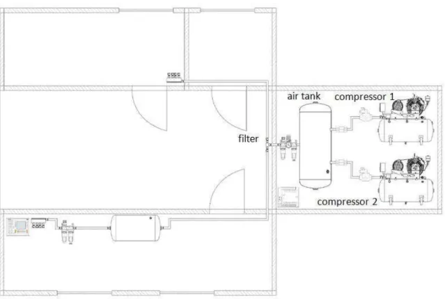
Due to the high level of noise emitted during their exploitation, piston compressors are always placed in separate rooms, known as compressor workshops [2]. To study this phenomenon, a room was established within the laboratory of the Division of Mechatronics, in which two piston compressors were placed. The aim in using these compressors is to deliver the pressured air that is utilized during laboratory work and classes for students. The
1 Faculty of Mechanical Engineering and Computer Science, University of Bielsko-Biała, 2 Willowa Street, 43-309 Bielsko-Biała, Poland. E-mail: [email protected].
2 Faculty of Mechanical Engineering and Computer Science, University of Bielsko-Biała, 2 Willowa Street, 43-309 Bielsko-Biała, Poland. E-mail: [email protected].
system of controlling the compressor workshop was designed and built to facilitate remote controlling and monitoring of performance, as well as effective usage of both compressors.
In the present paper, we describe a system for controlling an air compressor unit. The system mainly consists of the cooperation of two air piston compressors. One compressor has the function of a basic device supplying compressed air, while the second compressor is utilized as an additional device, supporting the performance of the basic (main) compressor. The application of an additional compressor in the discussed system ensures the delivery of pressured air, which offers adequate pressure in case of a temporary increase in the demand for pressured air. When designing the control system, we take into account the well-known (standard) hybrid structures of control systems, which control the process of delivering pressured air [1, 2].
2. CONTROL SYSTEM
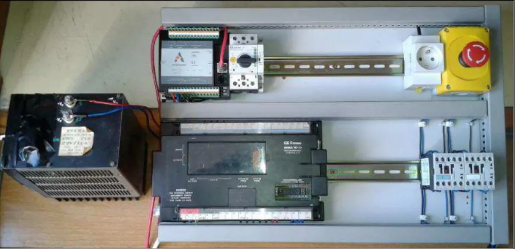
The basic assumption, which is made within the design process of the compressor stand’s control system, relates to the possibility for the remote monitoring and controlling the air compressor’s performance in situ, i.e., in the compression workshop. The system was built utilizing automation components, devices, subsystems etc. available from the Division of Mechatronics: namely, an Astraada RCC972 controller, a GE 90-20 controller, thermostatic gauges of temperature, a pressure converter equipped with a 4-20 mA analogy connection, a 22A 690V 24VDC contactor, breaking electrovalves based on the 24VDC solenoid (the so-called solenoid valve) and Proficy ME software.
At first, the software needed to control the performance of the compressors and the visualization of the processes was prepared. In the built system, the PACSystems RX3i modular controller was utilized. Regarding the possibility of an application using an Astraada controller and a GE 90-20 controller, an exchange of the controlling code, which was prepared using the Proficy ME 8.60 software followed by Cscape-based software, was performed. The Proficy ME software was utilized for the simulation phase of modelling and testing. The Cscape programme, meanwhile, allowed for the programming of the Astraada controller. Additionally, the Logicmaster 90 program was utilized for programming the GE 90-20 controller in order to service the two-stage (binary, bi-stated) inputs and outputs.
The simulation stand was built to test the controlling software, as well as check the correctness in the performance of controlling visualization possibilities. On the simulation stand, signals from the pressure converter were replaced by signals from current adjusters, while the signals from temperature bi-stated gauges corresponded to the signals from the simulation of bi-stated inputs.
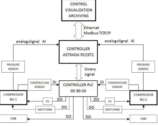
Fig. 2. The structure of the control system
3. ASSUMPTIONS FOR AN APPLICATION CONTROLLING AND VISUALIZING PERFORMANCE OF A COMPRESSOR
An application for controlling and visualizing the work modes of a system should have the following goals:
a) Services for users:
USER (monitoring of process parameters, approval of communications/alarms, switching between the screens)
ADMINISTRATOR (access on a lever of a user USER, changes to ultimate (threshold) values of parameters and versatile settings, approval of service actions related to the compressors, exchange of filters, oil etc.)
b) Service of alarms: demand concerning exchange of filters, communication too high, low temperature, error in communicating the vision gauge of the oil level, pressure too high/low, improper level of oil
c) Working in service mode: testing of binary outputs – release of the condensate, breaking valve, checking fan performance, possibility of simulating pressure values, temperatures and over-crossing of ultimate values aimed at testing the system
For the first phase, initialization of the compressor work mode is needed, i.e., it should be launched and run until the pressure level (in the compressor vessel) of p=600 kPa is reached. The value CISN>600 kPa is the analogy measurement utilizing the pressure converter. After this time, the motor of the compressor stops while waiting for the work mode of AUTO to be switched on. The AUTO work mode can be switched off at any moment (phase) in the current process by pressing the STOP button, which is located in the upper part of the panel. To activate the second compressor, the following activities must be carried out on the stand: the bi-stable button should be switched on, then the AKTYWACJA option should be activated on the visualization panel, such that the initialization of the first and second compressors are activated simultaneously when the switch on the stand is in the ON position, i.e., when the needed pressure value (at the level of 600 kPa) is reached.
The second compressor is launched when both the first compressor is in the AUTO work mode and the value of the algorithm for the velocity of changes drops below the threshold value.
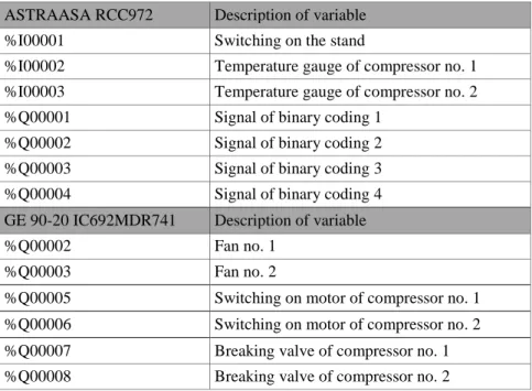
Table 1. List of variables controlling the layout of compressed air power
ASTRAASA RCC972 Description of variable
%I00001 Switching on the stand
%I00002 Temperature gauge of compressor no. 1
%I00003 Temperature gauge of compressor no. 2
%Q00001 Signal of binary coding 1
%Q00002 Signal of binary coding 2
%Q00003 Signal of binary coding 3
%Q00004 Signal of binary coding 4
GE 90-20 IC692MDR741 Description of variable
%Q00002 Fan no. 1
%Q00003 Fan no. 2
%Q00005 Switching on motor of compressor no. 1
%Q00006 Switching on motor of compressor no. 2
%Q00007 Breaking valve of compressor no. 1
%Q00008 Breaking valve of compressor no. 2
4. APPLICATION FOR CONTROLLING AND VISUALIZATION
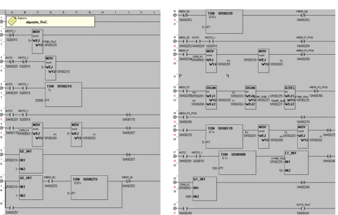
Due to the introductory assumption, the controlling application has been written by means of the Proficy ME software. However, due to some changes in the assumptions, we have converted the controlling application into Cscape software. The latter is compatible with Astraada RCC972 controllers. An exemplary fragment of the controlling code after conversion is presented in Fig. 3.
The GE 90-20 controller, together with Logicmaster 90 software, has been used in the control system. Its function is to create an upgraded module of binary (bi-state) outputs for the Astraada RCC972 controller.
Utilization of the GE 90-20 controller caused us to remove the 230VAC 10A transmitters, equipped with a 24V solenoid, from the final hardware configuration because the standard inputs of the controllers allow them to work as transmitters (up to a current value equal to 2A). Upgrading the system consisted of incorporating additional binary (bi-state) outputs, which was performed via adequate binary coding of the states on outputs of the main controller.
An exemplary control program, which controls the binary (bi-state) output %Q0005 in the GE 90-20 controller, is presented in Fig. 4. It was prepared by means of Logicmaster 90.
In Fig. 5, the main screen for the visualization of the working state and layout of the system is presented, whereas the panel of time histories and current values of chosen parameters is shown in Fig. 6. The software was prepared by means of Wonderware InTouch.
Fig. 3. Control code fragment in Cscape
Fig. 5. The main screen of the application
Fig. 6. View of the charts on screen
5. TEST INVESTIGATIONS OF THE CONTROL SYSTEM
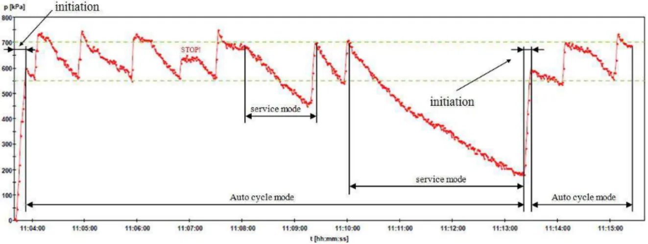
The prepared controlling system was subjected to test investigations in order to check the correctness in the performance of the application that allows for controlling as well as visualizing the work of the system. In Figs. 8 and 9, the chosen time histories of pressure in the first compressor, as registered during the test investigations, are presented.
Fig. 8. Process pressure changes of compressor no. 1 during the first test run
Fig. 9. Process pressure changes of compressor no. 2 during the second test run
6. FINAL REMARKS AND CONCLUSION
The system of control in air compressors, as described in the present paper, is installed in the didactic laboratory of the university. It has been built utilizing the Astraada RCC972 controller. The introductory tests and practical experiments confirmed that it works properly and reliably, as well as allows for remote controlling and monitoring of the work of the group of compressors delivering compressed air to the installation mounted in the didactic laboratory. The performed test investigations allowed for the formulation of additional conclusions appropriate to the possible development of the system. Based on our detailed observations, we can conclude that the system ought to be equipped with an additional pressure sensor in the main container of the compression workshop. Besides, with regard to the temperature sensors, which provide information about the temperatures of particular blocks in the compression system, it is necessary to mount additional air temperature gauges in the compression workshop. In order to perform an analysis of power consumption in relation to the supply of the compressor system, a measurement device should be incorporated into the system when performing reports on consumed energy, e.g., by using the current instrument transformers.
References
1. Baier A., G. Kost, J. Świder, R. Zdanowicz. 2012. Sterowanie i automatyzacja procesów technologicznych i układów mechatronicznych. [In Polish: Control and
automation of technological processes and mechatronic systems]. Katowice, Poland:
Publication of the Silesian University of Technology.
2. Liang H., X. Li. 2011. “Integrated Monitoring System Design of Hybrid
Air-compressors.” Procedia Engineering 15: 938-943. DOI: 10.1016/j.proeng.2011.08.173. 3. Sałat R., K. Korpysz, P. Obstawski. 2010. Wstęp do programowaniasterowników PLC. [In Polish: An introduction to programming the PLC drivers]. Warsaw, Poland: WKŁ. 4. Homišin J., P. Kaššay. 2014.“Experimental verification of the possibility using
pneumatic flexible shaft couplings for the extremal control of torsional oscillating mechanical system.” Diagnostyka 15(1): 11-16. ISSN 1641-6414.
5. Grega R., J. Krajňák. 2012. “The Pneumatic Dual-Mass Flywheel”. Scientific Journal of Silesian University of Technology. Series Transport 76: 19-24. ISSN: 0209-3324.
Received 25.11.2015; accepted in revised form 04.04.2016