_____________________________
*) Corresponding author: [email protected]; [email protected];
doi:
10.2298/SOS1001003V
UDK 666.122.3:661.875.2:621.375.826
The Layer by Layer Selective Laser Synthesis of Ruby
M. Vlasova
1*, A. Ragulya
2, V. Stetsenko
2M. Kakazey
1, P. A. Marquez
Aguilar
1, I. Timofeeva
2, T. Tomila
2, E. A. Juarez Arellano
11
Center of Investigation in Enginnering and Applied Sciences of the Autonomous
University of the State of Morelos (CIICAp-UAEMor), Av. Universidad, 1001,
Cuernavaca, Mexico.
2
Institute for Problems of Materials Science, National Academy of Sciences of
Ukraine, 3, Krzhyzhanovsky St., Kiev, 252680, Ukraine
Abstract:
In the work, features of the layer-by-layer selective laser synthesis (SLS) of ruby from an Al2O3–Cr2O3 mixture are considered depending on the irradiation power, the laser beam
traverse speed, the height and amount of the backfill of powder layers. It has been established that, under irradiation, a track consisting of polycrystalline textured ruby forms. The morphology of the surface of the track and its crystalline structure are determined by the irradiation conditions.
Keywords: Al2O3- Cr2O3 Powder mixture, Compact, Laser treatment, Ruby.
Introduction
It is known that corundum (α-Al2O3) finds extensive application in different fields of
engineering. The combination of high electric resistance and thermal conductivity provided its use in the production of integral circuits and substrates for chip casings. Alumina ceramics is used in nuclear power plants as a heat and an electric insulator in the active zone, for IR windows or as armor for low threat applications where thinner tiles can be used [1–4]. In recent years, along with traditional powder metallurgy methods for the synthesis of corundum ceramics, selective laser sintering has been developed [5], which makes it possible to combine complete and partial melting in a single cycle, i.e., to perform liquid-phase sintering. The next stage of development of this technology is layer-by-layer SLS. This method is based on stereolithography, which provides prototyping of layers [6–9], and enables one to obtain complex-shaped articles.
In layer by layer SLS of corundum, additives which play the role of binders of grains of the basic material in the stage of powder pressing and sintering are introduced in Al2O3
powder to provide the required density and strength of the consolidated material [8, 10–15]. Among corundum-based ceramics, ruby, which is a solid solution of chromium ions in the solid structure of the covalent Al2O3, is the most extensively used material. Ruby single
is possible to combine chromium diffusion in the aluminum oxide lattice, sintering of a disperse system, its melting and crystallization and elucidate features of the formation of ruby layers.
2. Experimental Technique
In this work, commercially available Al2O3 and Cr2O3 powders (Reasol,
ReactivoAnalitico, Mexico City) with a particle size of 40 nm and 1.8 μm, respectively, were used. The powders were mixed in the Al2O3: Cr2O3 weight ratio of 97:3. The obtained mixture
was pressed in compacts in the form of pellets 30 mm in diameter and 3 mm thick under a pressure of 5 MPa.
The compacts were irradiated with a continuous-action laser of with a wave length λ = 1064 µm (LTN-103 unit, Russia) at the values of the irradiation power P1 = 90 W,
P2 = 120 W, P3 = 160 W and P4 = 190 W. The diameter of the laser spot (d) was 0.2 mm and
0.8 mm. The laser beam was moved over the surface of the compacts at traverse speeds of a coordinate table (v) of 1.25 mm/s, 0.64 mm/s, 0.4 mm/s, 0.26 mm/s, and 0.13 mm/s. The system of vertical movement of a sample without changes in the size of the laser spot enabled us to perform additional operations on the surface of compacts.
With the laser unit, one-run and multiple-run treatment along the same path of compacts was performed. In the first case, on a surface the concave channel was formed. At multiple-run treatment an originally formed concave track was filled up by the powder mixture. A powder was consolidated and planed. After this procedure a filled channel was subjected to irradiation. The procedure of filling of the channel by a powder mixture and its irradiations again was repeated. The number of such backfills of channel and procedure of irradiation was from 2 to 12. Gradually above the specimen surface a convex track appeared. The height of backfill inside each series of experiments was constant. A series of experiments was realized in which the height of backfills was different: h1 = 125 μm, h2 = 250 μm,
h3 = 350 μm, and h4 = 500 μm.
An electron microscopy study and an X-ray microanalysis were carried out with a Superprobe-733 scanning electron microscope (JEOL, Japan) and a Scanning Electron Microscope SEM /FIB NOVA 200 (Bruker, Gemany). X-ray diffraction analysis of the specimens was performed using a Siemens D-500 diffractometer (Munich, Germany) in Cu Kα radiation. Infra Red (IR) spectra were obtained with a Specord M80 spectrometer (Karl
Zeiss, Germany). Electron Paramagnetic Resonance (EPR) investigations were performed with an X-band microwave spectrometer at room temperature (SE/X 2547-Radiopan, Poznan, Poland).
After irradiation the formed channels (tracks) represent a glazed material of red color. The tracks are easily extracted from friable pressings.
Using X-ray diffraction, IR-spectroscopy and the EPR method, tracks and layers of the material located under tracks at different depths were investigated. Note that the formed track is red. Under the track, a dense strong pink layer, which is difficult to separate from the track, is located. Below it, a loose grey–green layer, characteristic of the compact before treatment, lies.
To obtain micrographs, the track was cut by two methods, namely, along a diagonal in order to retain the lateral sides and bottom and perpendicularly to the surface of the track. Fractures of tracks were also investigated.
3. Experimental Results
3.1. Electron Microscopy
In one-run passing of the laser beam, a channel forms on the surface of the compact. The depth of the channel and the morphology of its surface depend on the irradiation parameters (P, v and d). For instance, with increase in the irradiation power (P) at v = const or with decrease in the beam traverse speed (v) at P = const, cavities and through holes form on the surface (Fig. 1a), which is due to complete melting and evaporation (ablation) of the material from the irradiation zone.
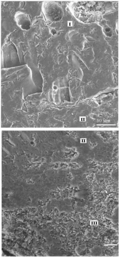
Fig. 1 Micrographs of channels formed in one-run (a) and four-run (b) treatment of a compact: P = 160 W; d = 0.2 mm. For (a), v = 0.26 mm/s (a). For (b), v = 1.25 mm/s. The height of each backfill (h) is 250 μm. Microsections were made of samples cut along diagonals of the channels.
In layer-by-layer building up of layers, a new-formed product gradually fills the channel zone. On a section of the channel, boundaries of layers are seen (Fig. 1 b). Between the layers, pores and cracks are present. As a rule, in the upper (external) layer of the channel, the size and the number of pores are larger than those in the volume between the layers.
Fig. 2. Micrographs of channels formed as a result of irradiation at P = 160 W and d = 0.2 mm. For (a), v = 0.64 mm/s; 4 layers of the backfill with h = 250 μm. For (b), v = 1.256 mm/s; 3 layers of the backfill with h = 375 μm. Microsections were made of samples cut along diagonals of the channels.
In a micrograph of the multilayer material formed in the channel (Fig. 3), it is seen that as the distance to the surface of the channel decreases, grains become coarser and their texturing occurs in the direction of movement of the laser beam.
The obtained data enable us to conclude that to form of a homogeneous material of the track and improve its strength, it is necessary to prevent the formation of a multilayer structure, i.e., to prevent pore formation and cracking. For this purpose, the irradiation power and beam traverse speed must be decreased, and the thickness of the backfill is to be minimized. In other words, conditions maximally close to conditions of growth of corundum crystals are required [17, 18].
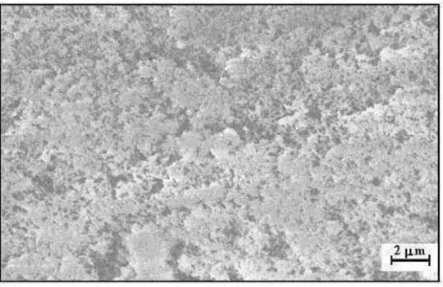
Fig.4. Micrograph of deposited ablation products.
The laser treatment of the compact surface is accompanied by the formation of ablation products, which deposit in the form of nanopowders (Fig. 4). According to the microanalysis data, the powder contains Al, O and Cr.
3.2. X-ray analysis
According to the X-ray analysis data, the main phase of the powder compacts is Al2O3
(corundum), which has a hexagonal lattice with constants a = 0.476 nm and c = 1.299 nm. In X-ray diffraction patterns, 2 weak lines with d = 0.24 and 0.167 nm, which are assigned to the strongest line of Cr2O3, are also present (Fig. 5). Thus, the powder compacts are mixtures of
crystalline phases, the contents of which correspond to the set ratio of the components.
Fig. 5. Fragment of X-ray diffraction patterns of the 97 wt. % Al2O3 + 3 wt. % Cr2O3 initial powder mixture (a), a
monolayer channel (b), a multilayer channel (c), and the surface layer of the multilayer channel (d). (o) Al2O3; (v)
For tracks formed by layer-by-layer SLS, at first, after one-run treatment, the interplanar spacing diminishes (d) and then rises with the number of layers and irradiation intensity increase (see Tab. I). In view that the ionic radiuses Cr3 + and Al3 + are 0.064 nm and 0.05 nm, accordingly, the obtained results can be explained by the fact that, at first, ions of Cr+3 penetrate into the Al2O3 lattice, and then some chromium ions leave the earlier formed
aluminum–chromium oxide. The appearance in X-ray diffraction patterns, of additional lines (d = 0.364 and 0.215 nm) (see Fig. 5), the location of which is close to those of lines of the Al9Cr4 intermetallic phase [19, 20], indicates the development of processes of destruction of
the aluminum–chromium oxide lattice.
Tab. I. Change of d100 in aluminum–chromium oxide in after laser treatment in different
conditions
Laser treatment type d100, nm Lattice type
Initial compacted mixture 0.2084 corundum One-run treatment,
P = 120 W, v = 1.25 mm/s
0.2069 aluminum chromium oxide (ruby)
2 layers of the backfill, P = 120 W, v = 0.64 mm/s
0.2075 aluminum chromium oxide (ruby)
4 layers of the backfill, P = 120 W, v = 1.25 mm/s
0.2076 aluminum chromium oxide (ruby)
4 layers of the backfill, P = 160 W, v = 1.25 mm/s
0.2078 aluminum chromium oxide (ruby)
4 layers of the backfill, P = 190 W, v = 1.25 mm/s
0.2079 aluminum chromium oxide (ruby)
Decreases on the interplanar spacings of the oxides and redistribution of the intensities of their lines testify to not only a change in the composition of the aluminum–chromium oxide in its homogeneity region, but also to the presence of defectiveness in it along the planes (113) and (116). Since a deviate of intensity of lines of the diffraction spectrum from standard values is typical for textured materials [22 - 24 ]. It is possible to assume that in this case texturing of the track material takes place. This assumption is in accordance with [25].
3.3. EPR Data
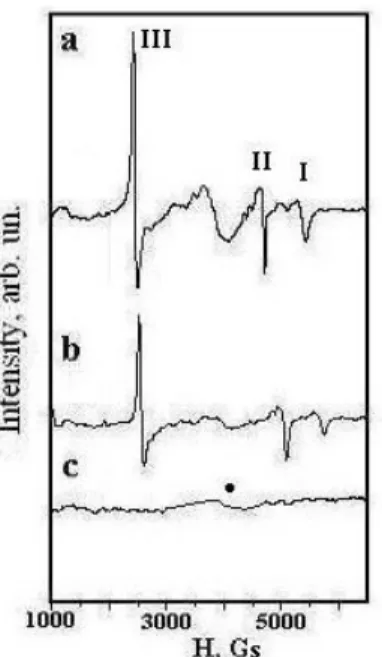
In the 97 wt. % Al2O3 + 3 wt. % Cr2O3 initial mixture, only a weak broad EPR signal,
which is due to the defective states of the α−Cr2O3 phase, is observed at g ~ 1.9 (Fig. 6 c). For
a red track, EPR lines are registered at gI ≈ 1.22, gII ≈ 1.47,, gIII ≈ 3.38, and gIV≈ 22 (Fig. 6
a). This spectrum is typical of polycrystalline ruby crystals [21, 25]. For the pink dense layer located under the channel, a ruby spectrum, which, however, has a lower intensity, is also observed (Fig. 6 b). For both the initial mixture and the lower layer, the EPR spectrum of ruby is absent, but a weak signal from αCr2O3 is recorded.
Thus, in the irradiation zone of the powder mixture, ruby is synthesized. For samples taken from layers located at larger distances from the track, the gradual weakening of the EPR spectrum of Cr3+ ions is due to lower temperatures in these regions and, hence, retardation of the entering of Cr3+ ions in the lattice of corundum. For instance, in the track, the content (c) of Cr3+ ions in Al2O3 is ~1.5 at. %, whereas in the sintered layer at a depth of ~2 µm, c ~ 0.5
Fig. 6. EPR spectra of the channel material (ruby) (a), sintered material located under the channel (b), and a lower layer (this EPR spectrum coincides with the spectrum of the initial powder mixture) (c).
3.4. IR Spectroscopy Data
IR absorption spectra of corundum for different layers of the material located under the track illustrate gradual weakening of the band at ν2 ~ 500 cm-1 as the distance to the track
decreases (Fig. 7, spectra 2–6). A spectrum obtained from the track is assigned to the spectrum of ruby [26] (see Fig. 7, spectra 1 and 6), which agrees with the EPR results.
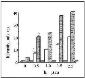
Fig. 8. Changes in the intensities of IR bands at ν1 ~ 460 cm-1 (1) and ν2 ~ 500 cm-1 (2) in
samples taken under a track at different depths h. The sample:KBr weight ratio is 1:300.
An interesting feature is that the intensities of all absorption bands decrease as the distance to the track decreases. For the track, the intensity of the spectrum appears to be much weaker than that for the subsurface layers (see. Fig. 8). The cause of the weakening of the spectrum is the formation of a shielding conductive phase. It is likely that this phase is Al9Cr4
[27], which was detected by the XRD. The weakening of the band at ν1 ~460 cm-1 in the
samples as the distance to the surface of the track decreases (see Fig. 8, curve 1) indicates the gradual accumulation of the intermetallic compound in the surface layer of the track.
4. Discussion
The SLS of ruby is a temperature process, the specific feature of which is high-temperature crystallization. In the development of the fundamentals of high-high-temperature crystallization, along with the study of the parameters determining directly its development (mechanism of growth, heat and mass transfer, and the accumulation of macroscopic inclusions and impurities in phase boundaries), the necessity of considering of some aspects of the chemical and physical kinetics (such as thermal dissociation in melting, high-temperature chemical interactions of the melt with an atmosphere of crystallization and with the container material, solid-state chemical reactions with the participation of point defect and impurities, etc.) appeared [28]. It has been established that the melts of high-temperature compounds are dissociated. For instance, the melting of aluminum oxide (under normal pressure) is accompanied by dissociation with the formation of Al, Al2, A12O, A1O, and
А12O2 ions under the melt [29]. In the melt, an excessive number of aluminum ions forms.
This leads to the development of the aluminothermic reduction of impurity oxides to the metal state [30]. On the other hand, the excessive number of ions of the solidified matter in the melt causes negative consequences, which are analogous to the action of foreign impurities. In this case, the effect of concentration overcooling, which disturbs the morphological stability of the crystal growth front and favors deviation of the contents of the main elements from the set stoichiometric formula up to the formation of other phases, is of particular importance.
Taking into account the aforesaid, it is precisely dissociation of А12O3 that is the main
cause of pore formation in the channel zone (in ruby). A part of vapor and gaseous products leave the melt, whereas the other part remains in the melt. At the same time, Cr2O3
In the process of building up each next layer (which is an analog of the process of monocrystal growth according to Verneuil), at first, beads of the gaseous product are forced out by the crystallization front. As the number of accumulated gaseous beads increases, a zone with a high content of inclusions forms. The melt gets free from gaseous components. As the crystallization process develops further, a zone containing a smaller number of gaseous inclusions forms.
As a result of the evolution of vapor products, a film which consists of highly disperse А12O3 and Cr2O3 particles forms on the substrate.
In all regimes of SLS, Cr3+ ions enter into the lattice of Al2O3, and ruby crystallites
form. The size of crystallites is determined by the crystallization conditions (the temperature gradient). Since in this case, crystallization from the melt occurs, as temperature decreases with distance from the laser-treated surface, the size of ruby crystallites decrease. The movement of the laser beam also sets a certain gradient on the surface and causes the directed motion of the cooling melt (under the action of hydrodynamic forces), which leads to the texturing of crystallites.
Along with the synthesis of ruby crystallites from the melt in the surface layer of the track, in the deep layers of the compact, sintering of corundum and entering of Cr3+ ions simultaneously occur. The degree of development of chromium diffusion process is determined by the temperature gradient.
The appearance of metallic aluminum in the alumina melt induces alumothermic reduction of chromium oxide, which is accompanied by the formation of Al9Cr4. According to
the IR spectroscopy data, the intermetallic is accumulated in the upper layer of the ruby track. Thus, the performed investigations have shown that, in essence, the SLS of ruby is close to the processes and methods of growth of corundum and sapphire both in the vertical and horizontal direction. It is assumed that the optimization of the SLS of ruby will make it possible to extend the field of application of this material in different branches of engineering.
5. Conclusions
1. It has been established that layer-by-layer SLS can be used for the synthesis of ruby from Al2O3 + Cr2O3 powder mixtures.
2. In the irradiation zone, a track, which consists of ruby crystallites textured in the direction of movement of the laser beam, forms.
3. On the surface of the ruby track, a conductive film on the base of Al–Cr alloys forms. 4. The porosity of the track and the morphological features of its surface depend on the irradiation parameters (the irradiation power, transverse speed of the laser beam, and its diameter) and the number of built-up layers.
5. The lower layers under the track consist of sintered polycrystalline ruby with different contents of Cr3+ ions.
Acknowledgement
The authors wish to thank CONACYT for financial support (Project 48361).
References
1. Yu. D. Tretyakov, Ceramics – Material of Future, Znanie, Moscow, 1987 (in Russian).
(in Russian).
3. Role of Ceramics in a Self-Sustaining Environment, Ed. R. Pampuch, K. Haberko, Faenza: “Techna”, 1997.
4. E. Dorre, H. Hubner, Alumina Processing, Properties, and Application, “Springer-Verlag”, New York, 1984.
5. http://en.wikipedia.org/wiki/Selective_laser_sintering. 6.
http://www.materialise.com/materialise/view/en/91755-Selective+Laser+Sintering.html.
7. I. V. Shishkovskii, Laser Synthesis of Functional Mesostructures and Bulk Articles, Fizmatlit, Moscow, 2008 (in Russian).
8. I. B. Shishkovskii, Selective Laser Sintering and Synthesis of Functional Structures, Author's Abstract of the Doctor's Degree Thesis (Physico-Mathemathical Sciences), Chernogolovka, 2005 (in Russian).
9. A. L. Petrov, I. V. Shishkovskii in: Collection of Works devoted to the 25th Anniversary of SF FIAN, pp. 148-161 “RIIS FIAN”, Moscow, 2005 (in Russian). 10. I. Shishkovsky, I. Yadroitsev, Ph. Bertrand and I. Smurov, Appl. Surf. Sci., 254
(2007) 996.
11. P. K. Subramanian, G. Zong, N. Vail, J W. Barlow, and H. L. Marcus, Solid Freeform Fabrication Proceedings, 1993, pp. 350-359
12. P. K. Subramanian, H. L. Marcus, Materials and Manufacturing Process, 10 (1993) 689.
13. A. Gahler, Heinrich J. G. Gunst, J. Am. Ceram. Soc., 89 (2009) 3076. 14. P. Bai, Y. Li, Sci. Sintering, 41 (2009) 35.
15. H. Ferkel, J. Naser, and W. Rechemann, Nanostructured Mater., 8 (1997) 457. 16. M. Hirishi, M. Takahiko, W. Moriaki, K. Yoshinori, Proceedings of the School of
Engineering of Tokai University, 39, 1999, pp. 95-99.
17. A. A. Blistanov, Crystals of Quantum and Nonlinear Optics, Izdatelstvo MISIS , Moscow, 2000 (in Russian).
18. M. V. Klassen-Neklyudova, Ruby and Sapphire, Nauka, Moscow, 1974. 19. H. Okamoto, J. Phase Equilib. Diff., 29 (2008)112.
20. JCPDS International Centre for Diffraction Data, Swarthmore, PA, 1996. 21. A. A. Manenkov, A. M. Prokhorov, Soviet Phys.- JETTP, 1 (1955) 611.
22. V. N. Lapatnikov, A. I. Gusev, Phys. Stat. Solidi, 48 (2006) 1546.
23. A. Larrea, G. F. de la Fuente, R. I. Merino, V. M. Orera, J. Eur. Ceram. Soc., 22 (2002) 191.
24. A. Larrea, V. M. Orera, R. I. Merino, J. I. Pena, J. Eur. Ceram. Soc., 25 (2005) 1419.
25. M. Kakazey, M. Vlasova, P. A. Marquez Aguilar, A. Bykov, V. Stetsenko, A. Ragulya, Int. J. Appl. Ceram. Tec., 6 (2009) 335.
26. A. G. Vlasova, V. A. Florinskaya, A. A. Venediktov, K. P. Dutova, V. N. Morozov, E. V. Smirnova in "Infrared Spectra of Inorganic Glasses and Crystals", Edited by A. G. Vlasova, V. A. Florinskaya, Izdatelstvo Khimiya, Leningrad, 1972 (in Russian).
27. P. Ozawa, S. Yoshizaki, S. Takeyama, T. Enjo, R. Ikeuchi, IEEE, 9 (1986) 391. 28. Kh. S. Bagdasarov, High-Temperature Solidification from Melt, Fizmatlit, Moscow,
2004 (in Russian).
29. I. S. Kulikov, Thermal Dissociation of Compounds, Metallurgiya, Moscow, 1969 (In Russian).
Са р а: У ј ј- - ј Al2O3–
Cr2O3 ј ј , ,
њ њ ј . У ђ ј ј ј
ј . М ј
ј ђ ј ј .