A Review of VF Controller for an
Asynchronous Generator Based Wind
Energy Conversion System
D.K.NISHAD
1Electrical Engineering, Dr.K.N.Modi Institute of Engineering & Tech. Modinagar,
Modinagar, UP-201204,INDIA
[email protected]
http://www.knmiet.edu
DIG VIJAY SINGH
2Electrical Engineering, Dr.K.N.Modi Institute of Engineering & Tech. Modinagar,
Modinagar, UP-201204,INDIA
[email protected]
http://www.knmiet.edu
DEEPAK SINGH
Electrical Engineering,ITS Engineering College, Greater Noida
[email protected]
Abstract:
VF controller for wind energy conversion system employing a self-excited asynchronous generator, that has the
capability for harmonic elimination, load balancing , and neutral current compensation along with voltage and
frequency. This paper presents a review of VF controllers, other related economic and technical aspects, and
their selection for specific applications. It is aimed at providing a broad perspectives or the status of VF
controller for researchers and application engineers dealing with VF controlling issues. A list of more than 50
research publications on the subject is also appended for quick reference.
Keywords:
Wind energy conversion system, self-excited asynchronous generator, four- leg voltage source
converter (VSC) , three-leg VSC , three-phase four-wire system, two –leg VSC , Voltage and Frequency
Controllers (VFCs)
1.
Introduction
main challenges for the squirrel cage asynchronous generator-based WECS are the control of voltage and
frequency. Therefore for satisfactory operation of WCES there is need of voltage and frequency controller.
In this paper a set of configurations of voltage frequency controllers (VFCs) for WECS using an asynchronous
generator are presented. These controllers mainly consist of voltage source converters (VSCs) with a BESS at
their DC link. These VFCs has the capability of having Bi-directional power flow i.e.; active and reactive
power flow by which they can control both voltage and frequency under varying consumer load and velocity of
wind. These VFCs also has the capability of eliminating harmonics and load balancing. [18]-[23]. There are the
3 section, the IInd section deals with the classification of VFCs for WECS for multiple functions as a VFC, such
as a load balancer, a load leveller, a harmonic eliminator and a neutral current compensator. In the IIIrd section
two types of control scheme are presented for WCES
2.
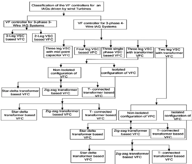
Classification of VFC’s.
There are various configuration of VFC is presented for an isolated asynchronous generator (IAG) driven by
wind turbine .These VFCs are based on the VSC along with BESS. These VFCs are mainly classified to feed
various types of three-phase three-wire or three -phase four -wire consumer loads shown in fig [1].
Fig. 1.Classification of VFCs for standalone wind power generating systems
2.1.
VFCs for Three-Phase Three-Wire IAG Systems
Various types of three phase three-wire loads using IAGs are presented below
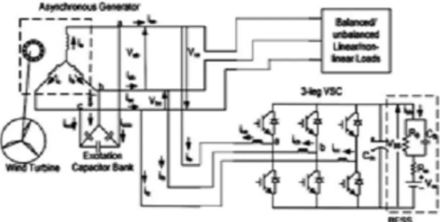
2.1.1. Three-Leg VSC-Based VFC:
2.1.2 Two-Leg VSC-Based VFC:
In this two-leg VSC-based VFC (see Fig. 3), two legs of VSC are connected to the two Phases and the third
phase of the generator is connected to the midpoint of the capacitors which is connected in parallel to the BESS.
In such a VFC configurations, it requires less number of switches.
Fig. 3.Two-leg VSC with BESS-based VFC for a three-phase three-wire IAG system.
2.2.
VFCs for a Three-Phase Four-Wire IAG System
Similar to VFCs for a three-phase three-wire IAG system VFCs for three-phase four- wire IAG system has
various topologies of VSCs with BESS at its DC bus for VFC. The advantage of using this three-phase
four-wire topology is that the voltage rating of the battery is selected at an optimum level and the transformer
provides the path for flowing for neutral current.
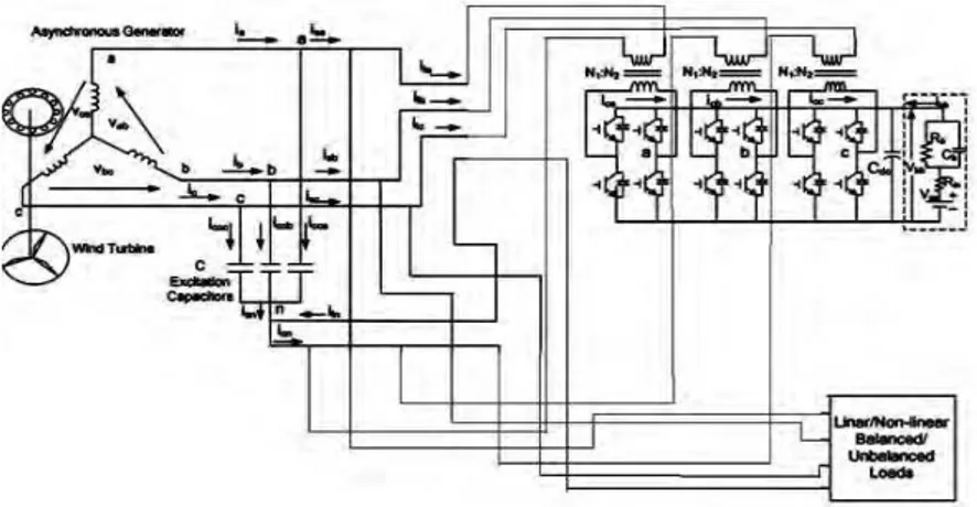
2.2.1. Three Single-Phase VSC as a VFC:
Fig. 4.Three single-phase VSC with BESS-based VFC for a three-phase Four-wire IAG system.
2.2.2. Three-Leg VSC with Midpoint Capacitors as a VFC
This system is made up of a three –phase four wire current controlled voltage source converter through which
the neutral terminal for the load is created through the midpoint of a pair of capacitors connected in parallel to
the BESS. It sis preferred due to its lower number of power semiconductor devices with regard to the four-leg
topology [51].
Fig. 5.Three-leg VSC and midpoint capacitor with BESS-based VFC for three phase Four-wire IAG system
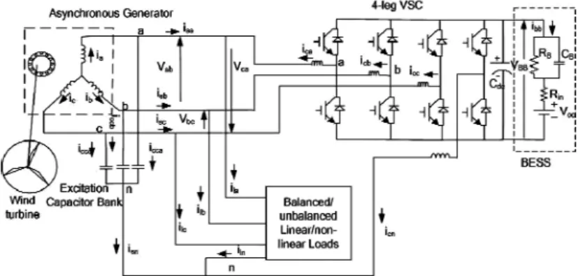
2.2.3 Four-Leg VSC as a VFC:
The excitation capacitor is in star form along with neutral terminal used for generating rated voltage at no load.
The neutral terminal of the excitation capacitor bank is connected to the consumer load this is the fourth leg of
proposed VFC (shown in fig 6.)
Fig. 6.Four-leg VSC and BESS-based VFC for a three-phase four- wire IAG system
2.2.4 Three-Leg VSC with a T-Connected Transformer as a Controller:
terminal is created through T-connected transformer for consumer load. shown in fig 7 and 8 These transformers
act as a path for a zero-sequence component of load currents while VSC along with the battery serves the
purpose of harmonic elimination, load balancing, load levelling,
Fig-7Three-leg VSC and non-isolated T-connected transformer with BESS-based VFC for a three-phase four-wire IAG system.
Fig -8 Three-leg VSC and an isolated T-connected transformer with BESS-based VFC for a three-phase four-wire IAG system.
3.
Conclusions
An extensive review of voltage frequency controller has been presented to provide a clear perspective on
various aspects of the VFCs to the researchers and engineers working in this field .A new VFCs have been
presented here for an isolated wind power generation system employing an isolated asynchronous generator
.The values of the AC inductor , DC link capacitor, DC link Voltage , and battery parameters have been
computed and their values can be selected on the basis of their performance , availability of the component and
according to the safety factors. For the three-wire WECS, three leg VSC with BESS –based VFCs is preferred to
control a three-phase three-wire IAG system because of reasonably good performance and low cost. and in the
case of four- wire WECS, four-leg VSCS with BESS based VFC is preferred for a three-phase four-wire IAG
system because of small size , reduced cost. Also an isolated zig-zag/star transformer and three-leg VSC with
BESS-based VFC are preferred for four-wire IAG system facilitating an optimum battery voltage and reduced
size of VSC.
References
[1] S. Heier, Grid Integration of Wind Energy Conversion Systems..Chichester, U.K.: Wiley, 1998.. [2] M. G. Simoes and F. A. Farret, Alternative Energy Systems. Boca Raton, FL: CRC Press, 2008. [3] I. Boldea, Variable Speed Generators. Boca Raton, FL: CRC Press, 2006.
[4] L. L. Lai and T. F. Chan, Distributed Generation—Induction and Permanent Magnet Generators. Chichester, U.K.: Wiley, 2007. [5] R. C. Bansal, “Three phase self excited induction generators: An overview,”IEEE Trans. Energy Conv., vol. 20, no. 2, pp. 292–299,
Jun. 2005.
[6] S.N.Bhadra, D.Kastha, and S.Banerjee, Wind Electrical System!st ed. New Delhi, India: Oxford Univ, Press, 2004
[7] B. Singh, S.S. Murthy and Sushma Gupta, “Transient analysis of selfexcited induction generator with electronic load controller supplying staticand dynamic loads” IEEE Trans. on Industry Applications, vol. 41, no. 5,pp.1194-1204, Sept 2005. [8] B. Singh, S.S. Murthy, S. Gupta, “Analysis and implementation of anelectronic load controller for a self-excited induction
generator” in IEEProc - Generation Transmission and Distribution, vol 151, no.1, pp. 51-60, Jan2004. [9] L. S. Pendell, “Induction generator system and method,” U.S. Patent 6788031B2, Sep. 7, 2004.
[10] S. C. Tripathy, “Performance of wind turbine self-excited induction gen- erator,” J. Inst. Eng. (India), vol. 75, pp. 115–118, Nov. 1994.
conversion scheme,” IEEE Trans. Ind. Appl., vol. 32, no. 1, pp. 57–65, Jan./Feb. 1996. [13] D. Seyoum, C. Grantham, and F. Rahaman, “The dynamic character- istics of an isolated self excited induction generator driven by a wind turbine,” IEEE Trans. Ind. Appl., vol. 39, no. 4, pp. 936–944, Jul./Aug. 2003.
[12] B. Singh, S.S. Murthy, S. Gupta, “An improved electronic load controller for self-excited induction generator in micro-Hydel applications” in IEEE Industrial Electronics Conference (IECON), vol. 3, 2-6 Nov. 2003, pp 2741 - 2746.
[13] J.M. Ramirez and Emmanuel. Torres M “An Electronic Load Controller for the Self-Excited Induction Generator” IEEE Transaction on Energy Conversion, vol. 22, no. 2, pp 546 – 548, June 2007.
[14] J.A.Barrado and R Grino, “Voltage and frequency control for a self excited induction generator using a 3-phase 4-wire electronic converters,” in Proc of 12th International IEEE Power Electronics and Motion Control Conference, Aug 2006, pp. 1419-1424. [15] T. Ahmad, M. Nakaoka and K. Nishida “Advanced active power filter for renewable energy application of standalone induction
generator,” 32nd annual Conf IECON 2005, Nov 2005, pp756-761.
[16] I. Tamrakar, L. B. Shilpkar, B. G. Fernandes and R. Nilsen “Voltage and frequency control of parallel operated synchronous generator and induction generator with STATCOM in micro hydro scheme,” in Proc IET – Gener..Transm. Distrib, vol.1, no. 5, pp 743-750, Sept 2007.
[17] B. Singh, S. S. Murthy, and S. Gupta, “Analysis and implementation of an electronic load controller for a self excited induction generator,” in Proc. Inst. Electr. Eng. Gener. Transmiss. Distrib., Jan., 2004, vol. 151, no. 1, pp. 51–60
[18] B. Singh, S. S. Murthy, and S. Gupta, “Analysis and design of STATCOM based regulator for self excited induction generator,” IEEE Trans. Energy Convers., vol. 19, no. 4, pp. 783–790, Dec. 2004..
[19] J. A. Barrado and R. Grino, “Voltage and frequency control for a self excited induction generator using a 3-phase 4-wire electronic converter,” in Proc. 12th Int. IEEE Power Electron. Motion Control Conf., Aug. 2006, pp. 1419–1424.
[20] IEEE Guide for Harmonic Control and Reactive Compensation of Static Power Converters, IEEE Standard 519, 1992.
[21] I. Tamrakar, L. B. Shilpkar, B. G. Fernandes and R. Nilsen “Voltage and frequency control of parallel operated synchronous generator and induction generator with STATCOM in micro hydro scheme,” in Proc IET – Gener.Transm. Distrib, vol.1, no. 5, pp 743-750, Sept 2007.
[22] J. Faiz, “Design and implementation of a solid state controller for regu- lation of output voltage of a wind driven self-excited three phase squirrel cage induction generator,” in Proc. IEEE. Eighth Int. Conf. Electr. Mach. Syst., Sep., 2005, vol. 3, pt. 3, pp. 2384–2388. [23] F. A. Farret, C. A. Portolann, and R. Q. Machado, “Electronic control b the load for asynchronous turbogenerators, driven by multiple
sources of energy,” in Proc. IEEE Conf. Devices, Circuits, Systems, 1998, pp. 332–337.
[24] D. Henderson, “An advanced electronic load governor for control of micro hydroelectric generation,” IEEE Trans. Energy Convers., vol. 13, no. 3, pp. 300–304, Sep. 1998.
[25] E. Suarez and G. Bortolotto, “Voltage-frequency control of a self-excited induction generator,” IEEE Trans. Energy Convers., vol. 14, no. 3, pp. 394–401, Sep. 1999.
[26] E. G. Marra and J. A. Pomilio, “Induction generator based system providing regulated voltage with constant frequency,” in Proc. Applied Power Electronics Conf., 1999, pp. 410–415.
[27] B. Singh and G. K. Kasal, “Voltage and frequency controller for a 3-phase 4-wire autonomous wind energy conversion system,” IEEE Trans. Energy Convers., vol. 23, no. 2, pp. 509–518, Jun. 2008.
[28] D. Joshi, K. S Sandhu, and M. K Soni, “Constant voltage constant fre- quency operation for a self-excited induction generator,” IEEE Trans. Energy Convers., vol. 21, no. 1, pp. 228–234, Mar. 2006.
[29] L. A. C. Lopes and R. G. Almeida, “Wind-driven self excited induction generator with voltage and frequency regulated by a reduced rating voltage source inverter,” IEEE Trans. Energy Convers., vol. 21, no. 2, pp. 297– 304, Jun. 2006.
[30] S. Choi and M. Jang, “Analysis and control of a single-phase-inverter- zigzag-transformer hybrid neutral-current suppressor in three-phase four- wire systems,” IEEE Trans. Ind. Electron., vol. 54, no. 4, pp. 2201–2208, Aug. 2007.
[31] B. Singh, V. Garg, and G. Bhuvaneswari, “A novel T-connected autotransformer-based 18-pulse AC–DC converter for harmonic mitigation in adjustable-speed induction-motor drives,” IEEE Trans. Ind. Electron., vol. 54, no. 5, pp. 2500–2511, Oct. 2007.
[32] N. Mohan, T. M. Undeland, and W. P. Robbins, Power Electronics: Con- verters, Applications and Design, 3rd ed. Singapore: Wiley, 2004.
[33] M. H. Rashid, Power Electronics, Circuits, Devices and Applications, 3rd ed. Singapore: Pearson Prentice-Hall, 2004.
[34] C.A. Quinn and N. Mohan, “Active filtering of harmonic currents in three-phase four wire systems with three-phase and single phase non- linear loads,” in Proc. IEEE Appl. Power Electron. Conf. (APEC’92), pp. 829–836.
[35] M. Karimi-Ghartemani and M.R. Iravani, "A method for synchronization of power electronic converters in polluted and variable frequency environments", IEEE Trans. Power Systems, Vol. 19, No. 3, pp. 1263-1270, August 2004.
[36] C.A. Quinn andN. Mohan, "Active filtering ofharmonic currents in tree-phase four-wire systems with three-phase and single-phase non-linear loads", Applied Power Electronics Conference, pp. 829-836, 1992.
[37] J.A. Barrado and R. Grin6, "Analysis ofvoltage control for a self- excited induction generator using a three-phase four-wire electronic converter", 9th Spanish Portuguese Congress on Electrical Engineering, 30 June-2 July 2005, CD-ROM, ISBN: 84- 609-5231-2.
[38] B. Singh, K. Al-Haddad and A. Chandra, "Harmonic elimination, reactive power compensation and load balancing in three-phase four-wire electric distribution systems supplying non-linear loads", Electric Power Systems Research, vol. 44, pp. 93-100, 1998. [39] Sekhar,T.C.,Muni, B.P. (2004). “Voltage Regulators for Self Excited Induction Generator” TENCON 2004, IEEE Region
10 Conference vol. 3, pp. 460-463.
[40] B. Singh, S.S.Murthy and S.Gupta, “An improved electronic load controller for self-excited induction generator in micro-hydel applications”,IEEE Annual Conference of the Industrial Electronic Society, Vol. 3, pp. 2741-2746, 2-6 November 2003. [41] Luiz A.C. Lopes and R.G. Almeida, “Wind-Driven Self-Excited Induction Generator With Voltage and Frequency Regulated
by a Reduced-Rating Voltage Source Inverter,” IEEE Trans.Energy Convers., vol. 21, no.2, June 2006.
[42] M. Karimi-Ghartemani, H. Mokhtari, M. R. Iravani, and M. Sedighy, ”A Signal Processing System for Extraction of Harmonics and Reactive Current of Single-Phase Systems,’’ IEEE Trans. Power Delivery., vol.19, no. 3, pp. 979 – 986, July 2004.
[43] J. Hurng-Liahng, W. Kuen-Der, W. Jinn-Chang and C.Wen-Jung, “A Three-Phase Four-Wire Power Filter Comprising a Three-Phase Three-Wire Active Power Filter and a Zig–Zag Transformer, IEEE Trans. Power Electron., Vol. 23, no. 1,pp. 252-259, Jan.2008.
[44] P. Mitra and G.K. Venayagamoorthy, "An Adaptive Control Strategy for DSTATCOM Applications in an Electric Ship Power System," IEEE Trans. Power Electronics, vol.25, no.1, pp.95-104, Jan. 2010.
[46] Jayaramaiah, G.V., and Fernandes, B.G.: ‘Analysis of voltage regulator for a 3-phase self-excited induction generator using current controlled voltage source inverter’. Proc. on First Int. Conf. on Power Electronics System and Application 2004, November 2004, pp. 102–106
[47] Freitas, W., Asada, E., Morelato, A., and Xu, W.: ‘Dynamic improvement of induction generator connected to distribution system using a DSTATCOM’, Power System Technology, 2202. Proc. Power Con. 2002, Int. Conf., October 2002, vol. 1, pp. 173–177
[48] S. C. Kuo and L. Wang, “Analysis of voltage control for a self-excited induction generator using a current-controlled voltage source inverterv (CC-VSI),” Proc. Inst. Elect. Eng., Gen., Transm. Distrib., vol. 148, no. 5, pp. 431–438, Sept. 2001.
[49] E. Suarez and G. Bortolotto, “Voltage-frequency control of a self-excited induction generator,” IEEE Trans. Energy Convers., vol. 14, no. 3, pp. 394–401, Sep. 1999 .
[50] J.A. Barrado and R. Grino, “Voltage and frequency control for a self excited induction generator using a 3-phase 4-wire electronic converters,” in Proc of 12th International IEEE Power Electronics and Motion Control Conference, Aug 2006, pp. 1419-1424.
[51] S. Choi and M. Jang, “Analysis and control of a single-phase-inverter-zigzag-transformer hybrid neutral-current suppressor in three-phase four-wire systems,” IEEE Trans. Ind. Electron., vol. 54, no. 4, pp. 2201–2208Aug. 2007