30
Scientific Bulletin of the „Petru Maior” University of Tîrgu Mureş Vol. 11 (XXVIII) no. 2, 2014
ISSN-L 1841-9267 (Print), ISSN 2285-438X (Online), ISSN 2286-3184 (CD-ROM)
ENERGY MONITORING AND LOAD CONTROL.
APPLICATION FOR AN OFF-GRID PV SYSTEM.
Karoly RONAY
1,
Dorin BICĂ
2, Cristian DUMITRU
31 Doctoral student - Technical University of Cluj-Napoca 1 [email protected]
2,3Petru Maior University of Târgu Mureş
2
Abstract
This paper describes the energy monitoring and load control processes as an important part of a renewable energy management system. The main objective of the work is to design a management system for a commercial off-grid consumer that uses solar and biomass energy and to present the monitoring and control processes of this system. The proposed method for this work is to use a micro-controller for the measuring of electrical and other non-electrical parameters of the system, to process the data and to adapt a control process to the technological procedure. The monitoring and control processes are implemented locally on a PC, or from a web application. With this approach an optimal and efficient management system can be adapted for new or existing systems by following and optimizing the technical processes for economic and energy efficiency.
Key words: microcontroller voltage-current measurement, battery and load management, html web application,
MOSFET switching techniques
1. Introduction
The main idea of the paper is to present the methodology and implementation of the monitoring and load control processes of an electrical commercial consumer system that uses renewable energy sources [1], in an off grid power network configuration. This approach is based on a case study of a hydroponic greenhouse powered by renewable energy sources and the management system adapted to this. An important part in developing a management system is represented by the information gathering process about the system parameters. To study and design the management system for the consumer with a predefined technological process (hydroponic greenhouse) [10], the power consumption and the type of the consumers in that process is required. The requested power depends on the technological process used and on the availability of the renewable energy sources [4]. Knowing these parameters, an energy management unit can be designed and developed for the energy production and consumption system.
One of the main issues is the diversity of the needed information, electrical parameters such as: current, voltage, battery state, solar PV (Photovoltaic) system parameters, and technological parameters of the power consumer system such as: temperature,
light intensity. Another problem is processing different type of data from different sensors or from other sources. The objective is to monitor the system parameters and to control the electrical consumers in the technological process in function of the PV solar system energy availability and battery bank charging level [7].
The proposed solution to solve the mentioned problems is represented by the use of a dedicated embedded microcontroller system. The system can be composed by one or more microcontrollers for the entire hardware and software system management. The electrical measurements and the information gathering is performed by using the analog input ports for the followed parameters and the control of the electrical consumers and battery charging is performed by using the digital and analog PWM (Pulse Wide Modulation) outputs for driving power electronics, like high power relays and MOSFETs (Metal Oxide Semiconductor Field Effect Transistor) for the electrical loads [3].
2. Equipments and methods overview
31
was to find suitable renewable energy sources, for both electrical and heat necessities. The optimal solution in this case is a solar PV system [2, 9] with battery storage for the electrical network and biomass heating system, which has electrical consumers.The proposed electrical power system is based on a DC power network [8] for safety and other technological reasons, presented in Fig.1. The solar PV system is used to power the electrical consumers and battery banks for the energy storage.
Fig. 1- Electrical power system structure of the hydroponic greenhouse
The proposed approach presents solutions to solve a number of tasks such as electrical measurements, optimal load control and parameter data stream from this system to a client application.
For this assignment the following methods and equipments were used: a microcontroller development board, dedicated sensors for measuring the system parameters, a communication Ethernet module for the web server, which is hosted and streamed by the microcontroller, as an HTML type web application. The main purpose of the web application is to illustrate the measured voltage, amperage, the power consumption and the solar PV charger state in real time. This web application has the option to manual switch on-off electrical loads and different settings from the distance.
All of these tasks are implemented with the use of a single microcontroller board. The main reason to use a development board is to adapt more easily to the system, to experiment and modify quickly the circuits and test them on site to improve the functionality of the existing electrical circuit.
The development board used in the experiments is an Arduino UNO board, with a ATmega328 microcontroller in it. One of the main advantages of the Arduino board is the tested and reliable hardware and software construction, with standard input and output pin configuration, communication and software upload directly through USB. The microcontroller comes with his own boot loader and the Arduino IDE programming software [5]. Beside
of these characteristics, it also has a large range of compatible modules: sensors, displays, high power shields for electric motors, wired and wireless communication modules.
In the construction process, the electrical circuit is built around this development board using breadboards, where the different kind of sensors and auxiliary electrical circuits are built.
The prototype breadboard circuit contains the following components: the DC voltage sensor, made by a resistive voltage divider circuit for voltage measurement, the ACS712 integrated current sensor (see in Fig. 2), and the power electronics for the solar PV battery charging and the electrical load controller circuit formed by P and N channel MOSFET transistors.
The communication with the network is realized through the Ethernet Shield module, compatible with the Arduino development board and it has a dedicated library with the communication functions in the IDE [6]. The Ethernet shield is a modular device that can be attached on the development board. In this case the Ethernet shield connects to a router and it is programmed in the header file to have a local IP address and a unique MAC address on the network [6]. The web application is generated by the microcontroller, in real time, and it is HTML type web page accessed by an internet browser.
3. Energy monitoring and load control
implementation in microcontroller
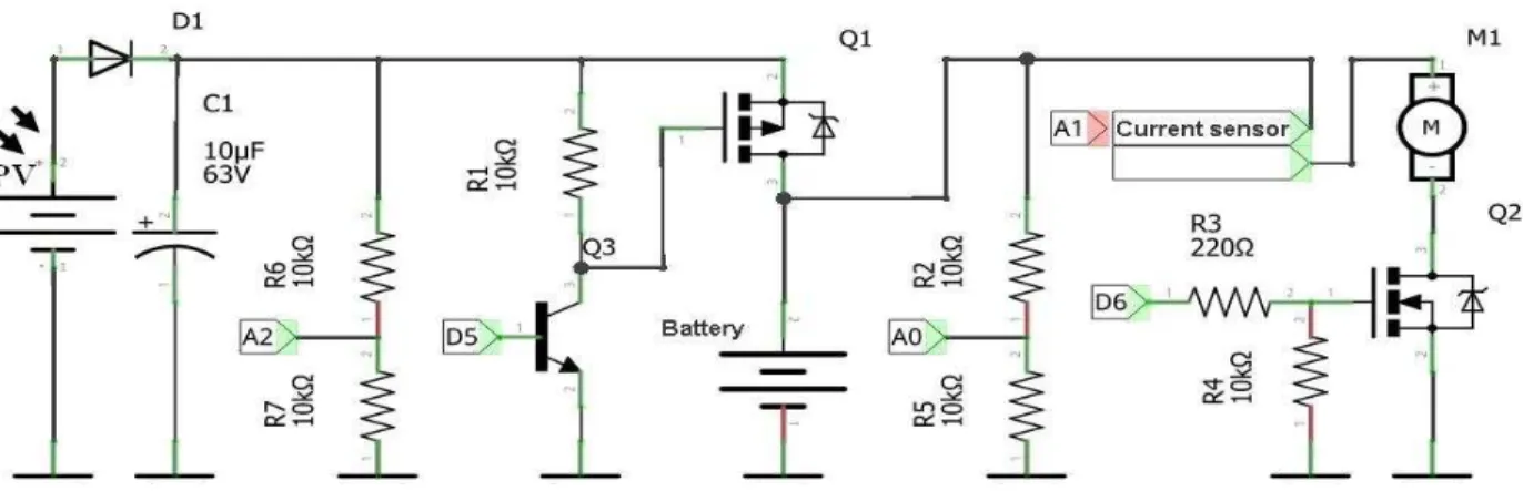
The presented electrical schematic in Fig.2 is designed for low voltage operation and for weak currents. The circuits were implemented for study and experimental purposes and it represents real physical models, only in a low power scale.
Analyzing further, the Fig. 2 presents the schematic of the electric circuit for the energy monitoring and load control, which contains a solar PV panel, rated at 5V, this represents the renewable power source, the power filter capacitor, the voltage measurement point for the solar PV panel, connected to the A2 analog input port of the microcontroller, where the analog measurements have a 10 bit A/D resolution (0-1023), from a 0-5V range. The used function to read the analog measurements is analogRead(A2). Another important part of the circuit is the battery, a 3.7V Lithium Polymer type, with internal protection and charge limiter. The battery voltage and the charging level are monitored through the A0 point.
32
by the PV panel voltage reading and the battery discharge level. If the battery is discharged below a certain admissible level, for example at 3.4V where the nominal voltage is 3.7V and the maximum charged level is 4.2V, and the solar power is available, which means that the PV panel generates around 4.5-5V, then the gate of the Q1 is switched on to open and charge the battery.The actual switching is the ON/OFF type, where the gate is open until the battery is charged or the solar PV panel voltage drops. Also it can be controlled in PWM mode, with the analogWrite() function which has a scale of 0-255 values, where the 255 value is the 100% duty cycle. When full charging option is available, the duty cycle is set around 90-95% and it is in function with the actual battery type configuration.
The battery supplies power to the electrical consumer, in this model the consumer is a DC motor. The energy metering is in the front of the electrical consumer, in this case in front of the DC motor. The energy metering section is represented by the Hall Effect current sensor ACS712. The current sensor has a sensitivity of 185mV/A and the full scale of measuring is 0-5A. The sensor output is connected to the A1 analog input.
The microcontroller energy measurement involves components such as time, current and voltage. The time measurement is performed with the millis() function and converted in seconds. The other two parameters, the voltage and current are obtained by the analog reading of 150 samples over 2 seconds, and then an average value is calculated. The total current is incremented as the total current and the actual current readings sum. With the obtained values, the energy is the product of the current reading and voltage in time. To control the electrical load, an N channel MOSFET was added into the circuit. The transistor Q2 is a low side switch with the gate controlled by the digital output D6 through a resistor. This part of the circuit is important for the load which is disconnected if the battery discharges beyond the minimal level. The microcontroller also transmits the values, like the charging state of the battery and the
consumer connectivity to the power system. This information is transmitted through the serial data monitor, used for debugging and local monitoring, and also to a web server application over the network [3].
4. Physical model and results
In the Fig. 3 the experimental physical model is presented. This model was build to study, develop and make laboratory experiments. In this phase of the work, the monitoring and controlling processes are implemented and the web server and the web application are running, Fig. 4.
Fig. 3- The main schematic of the monitoring and control circuit with the microcontroller
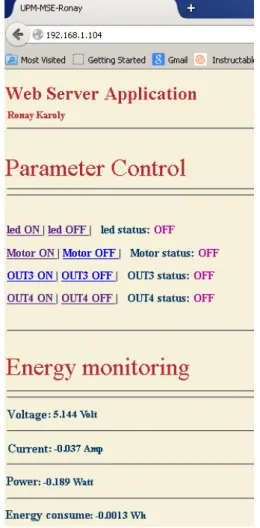
The web application can be accessed in the local network by typing the address given in the software. Example of the local area network address used, is 192.168.1.104., and it can be accessed from the internet, through an open port. For example, in the 5.15.9.219:50006 address, where the last five digits
33
represent the open port for the internal address. The sequence /?L1=0 at the end of the address represents the string that controls the L1 switch in the program, in this case a digital output and a LED for testing. The application reads the string and then executes the task. L1=0 means that the output is low and L1=1, the output is at a high value and the LED is on. Also, the electrical load, in this case the DC motor, can be turned on and off from the web application and gets the status of the current state.Fig. 4- Web application interface for monitoring and controlling parameters
The control can switch to manual or to automatic. The status gives the feedback of the actual state. The next section is the monitoring, where the solar PV panel voltage, battery voltage, battery status, the current used in the circuit, the actual power and the energy consumed can be followed. It can also be accessed by a mobile phone at an automatically page refresh rate of 5s. In this phase the page can be accessed by a regular internet browser on the phone or tablet device.
5. Conclusion and future development
The monitoring and control processes represent an essential part in the energy management and the
constructed experimental stand contains all the necessary components of a functional model for educational purposes.
The main objectives of this work was to study and design an experimental model for monitoring an off-grid solar PV system, control the battery charging process and electrical loads. Another important aspect is the option of monitor and control through the internet browser, in real time.
The experiments with the development boards and breadboards were successful, because the main circuit design changed often, due to progressing work and the changes were easily made. The communication between the server part and the client was successful implemented, but in the future it has to be optimized on the software level and on the peripheral hardware. Also a future development is represented by a database for the web application, and a new user friendly type of interface, for a better understanding of problems.
Acknowledgment
The research presented in this paper was supported by the European Social Fund under the responsibility of the Managing Authority for the Sectorial Operational Programm for Human Resources Development, as part of the grant POSDRU/159/1.5/S/133652.
References
[1] Rónay.K, Dumitru CD, Gligor A. Management of a Power System Based on Renewable Energy, Scientific Bulletin of the Petru Maior 2012; 9(1): 38-42
[2] Bică D, Dumitru CD, et. Al. Isolated Hybrid Solar-Wind-Hydro Renewable Energy Systems, Renewable Energy, in InTech, December 2009 [3] Rónay.K, Dumitru CD, The Monitoring and
Control Processes of a Renewable Energy Management System, INTER-ENG 2014 [4] Soteris K. Solar Energy Engineering - Processes
and Systems. 1st Edition , Elsevier Academic Press UK, 2009.
[5] Blum J, Exploring Arduino. Tools and Techniques for Engineering, Indiana, 2013 [6] Margolis M, Arduino Cookbook, 2nd Edition,
O’Reilly Media, Inc.2011
[7] Gertz E, Di Justo P, Environmental Monitoring with Arduino, Maker Media, Inc, 2012
[8] Keyhani A,Marwali M,Integration of Green and Renewable Energy in Electric Power Systems, Wiley, 2010
[9] Mukund R,Wind and Solar Power Systems, CRC Press LLC, 2000