Journal of Applied Research and Technology 585
New Sensor Cable for the Detection and Location of Leaks in
Pipelines for Transportation of Hydrocarbons
E.Orduña-Reyes*, R.Téllez-García
Instituto Mexicano del Petróleo,
Eje Central Lázaro Cárdena No. 152, San Bartolo Atepehuacan, 07730 Distrito Federal, México.
ABSTRACT
At present, hydrocarbon leaks, generated mainly by corrosion of pipelines, cause large economic losses for Mexico. These leaks constitute a problem of serious consequences in Mexico and in other countries in the world. This work describes the results of the tests conducted on a new sensor cable for the detection and location of leaks in pipelines for transportation of hydrocarbons. When a liquid or gas enters in contact with the wall of the sensor cable, it causes a short circuit in the wires; changing the measurement of the resistance may detect and locate the leak. The new sensor cable that is presented in this article has advantages over cables with similar characteristic made in other countries. The use of this sensor cable in pipelines of PEMEX will avoid economic losses, environmental damage and risks of possible explosions to the population. The experimental results demonstrate these advantages.
Keywords: leaks, detection, electrical resistance, pipeline.
RESUMEN
Actualmente las fugas de petróleo, generadas principalmente por corrosión del ducto, causan pérdidas económicas a México. Las fugas son un problema de graves consecuencias en el país y en otros países del mundo. Este trabajo describe los resultados de las pruebas realizadas en un nuevo cable sensor para la detección y localización de fugas a lo largo de ductos de transportación de petróleo. Cuando un líquido o gas entra en contacto con la pared del cable sensor que está en contacto con el ducto, éste traspasa un aislante entre los alambres conductores y la lana de acero, lo que hace que los alambres se pongan en corto circuito. El cambio en la medición de la resistencia permite detectar y localizar la fuga. El nuevo cable sensor que se presenta en este artículo tiene ventajas con respecto a cables con similares características de fabricación extranjera. La utilización de este cable sensor en los ductos de PEMEX permitirá evitar pérdidas económicas, daños al medio ambiente y riesgos para la población por posibles explosiones. Los resultados experimentales demuestran estas ventajas.
1. Introduction
To achieve an effective management of the integrity of pipelines during their operation is recommendable that they be designed and built with systems of mechanical protection (covering) and cathodic protection against corrosion. Due to the great importance that safe supply of hydrocarbon and its products represents for any country, security has always been, and it will continue to be, a high priority factor for facilities related with the oil industry. The application of norms and procedures with personnel qualified to react promptly and efficiently in the event of an emergency, it will be the way to protect the workers and facilities used in the production,
transportation, processing and distribution of hydrocarbons.
In 2001, Trans-Alaska pipeline suffered an accident in the United States of America causing the loss of more than 100,000 gallons of hydrocarbon which were spilled into the ecosystem. Corrosion is the principal problem causing hydrocarbon leaks.
New Sensor Cable for the Detection and Location of Leaks in Pipelines for Transportation of Hydrocarbons,E.Orduña‐Reyes / 585‐589
Vol. 10, August 2012 586
The main objective of the leak detection and location system for pipelines is for the detection to be almost immediate since it detects small hydrocarbon leaks; because of that, there would not be big spills and, in consequence, there would not be big risks for the population, wild life and contamination of Earth and water-bearing strata.
2. Principle of Operation
In this section, we describe the principle of operation of the sensor used in the experiments and simulate different failure scenarios of the pipeline. It also describes the fault detection and location principle.
The fault detection and location principle is based on measurement of electrical resistance, and its location is linearly related to distance, according to Ohm's law.
The principle of operation of this system is based on electrical impedance. The current that circulates through the sensor cable produces a fall of tension or voltage along the cable, the voltage is constant for each one of the lines (wires), in each line the voltage is measured with reference to zero potential (as Figure 1); hence, to verify that they have not suffered any change of their value of known resistance, the presence of a fluid in the sensor cable, produces a short circuit at one line or several lines with reference to zero potential, the resistance variation allows determining the location of the leak [1][2].
Figure 1. Monitoring the sensor cable.
3. Experimental Procedure
Figures 2 and 3 present a general view of the sensor cable, which consists of a group of several copper wires, NiCrome 80% - 20%, caliber 24 (0.5100 mm), connected in parallel arrangement, at a distance from each other of 0.0010 m, to detect several leaks simultaneously (that is in “multi-failure way”); the phase of the product
transported through the pipeline is not important. The resistance of the cable is known and very precise for each meter; a gummed paper is used as insulating material, between the wires and the layer of steel wool to give it flexibility and resistance.
The insulating material separates electrically the wires. This insulation is completely sensitive to the flow and pressure of the fluid. This group of wires is covered with polyethylene plastic; the inferior part will be in contact with the pipeline, which contains a diversity of perforations, which allow preventing and detecting leaks in pipelines.
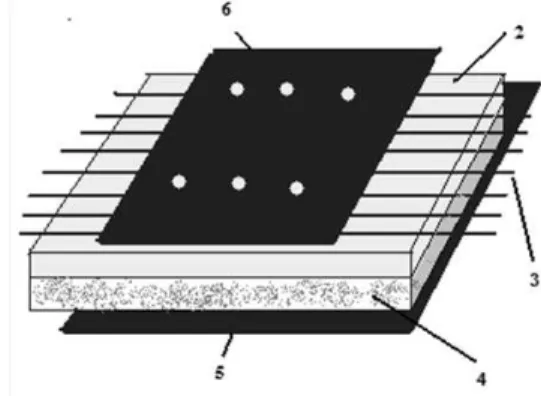
Figure 4 shows the layout of the sensor cable observed in a pipe that transports a fluid; this pipe may be rigid or flexible. The pipe is covered totally longitudinally with the sensor cable. In the inferior part of the sensor, the plastic cover has a diversity of perforations to allow the hydrocarbon leak to penetrate the cable and break the insulating material between the cables in parallel and the layer of steel wool, this makes the steel wool put several wires in short circuit, which causes the resistance of the wires to vary while being constantly monitored by a computer system so that the exact location of the hydrocarbon leak can be identified. The sensor cable may locate the axial and angular position of the leak.
Figure 2. Front and rear view of the sensor cable.
New Sensor Cable for the Detection and Location of Leaks in Pipelines for Transportation of Hydrocarbons,E.Orduña‐Reyes / 585‐589
Journal of Applied Research and Technology 587 Figure 4. Layout of the cable in the pipe.
Description of the parts in Figures 3 and 4: 1. - pipe
2. - insulating material 3. - wire parallel 4. - steel wool
5. - polyethylene plastic cover
6. - polyethylene plastic cover with holes
4. Results and Discussion
On a pipe of steel of 0.1016 m of diameter and 30 m length, we simulate eight different leaks (0.00317 m, 0.00635 m, 0.00952 m, 0.0127 m, 0.01587 m, 0.01905 m, 0.02222 m, 0.0254 m) making holes on the wall of the pipe, and end of the pipe being sealed and the other end having a small opening, where water was put in for pressure purposes. Each of the simulated leaks was tested one at a time; while a leak was being tested, the other holes remained sealed. Four types of tests were conducted; the first one consisting in testing the pipe at a constant 100 psi pressure. The simulation of each of the leaks was performed and the time needed for the sensor cable to detect and locate the leak was recorded. It was possible since the resistance of the sensor cables was measured. It was made this way for the eight simulated leaks.
The second test was conducted in the same manner as the first test, the only change was the pressure, now of 200 psi. The third test was of a constant leak of 0.00317 m, the pressure was varied from 5 psi to 250 psi, and the time needed for the sensor cable to detect the leak was recorded. The last test was of a constant leak of 0.0127 m and the pressure was varied from 5 psi up to 250 psi.
Figure 5 shows the response time of the sensor cable when tested at a constant pressure of 100
psi; the dimensions of the simulated leaks were changed from 0.00317 m with increments of 0.00317 m to 0.0254 m. Figure 5 shows the response times with the simulated leak of 0.01905 (around 50 s) and with the one of 0.025.4 m (which increased considerably around the 230 s).
Figure 5. Response time with pressure of 100 psi.
Figure 6 shows the response time of the sensor cable when tested at a constant pressure of 200 psi and the dimensions of the simulated leaks are varied from 0.003175 m with increments of 0.003175 m up to 0.0254 m; the graph shows the response time of the sensor cable, with a simulated leak of 0.00952 m, is around 4 s whilst the response time of the sensor cable with a simulated leak of 0.00254 m increases substantially around 150 s.
Figure 6. Response time with pressure of 200 psi.
New Sensor Cable for the Detection and Location of Leaks in Pipelines for Transportation of Hydrocarbons,E.Orduña‐Reyes / 585‐589
Vol. 10, August 2012 588
Leak located at 100 psi Known Measure
1 m 0.98 m 1.5 m 1.6 m
3 m 2.8 m
9 m 9.3 m
15 m 14.7 m 21 m 21.4 m 25.5 m 24.8 m 29.5 m 29.2 m
Table 1. Leak located at 100 psi.
Leak locate at 200 psi
Known Measure
1 m 1.1 m
1.5 m 1.7 m
3 m 2.8 m
9 m 9.2 m
15 m 15 m
21 m 21.2 m
25.5 m 25.1 m
29.5 m 29.3 m
Table 2. Leak located at 200 psi.
Figure 7 shows the response time of the sensor cable when simulating a leak with a constant diameter of 0.003175 m, the pressure is made to vary from 5 psi up to 250 psi. The graph shows how the response time of the sensor cable, with a pressure of 250 psi, is approximately of 0.05 s; with 60 psi, it is approximately of 20 s; and with a pressure below 60 psi, the response time increases considerably, up to 150 s.
Figure 7. Response time with a diameter of 0.00317 m.
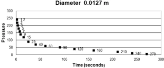
Figure 8 shows the response time of the sensor cable when simulating a leak with a constant diameter of 0.0127 m; the pressure is made to vary from 5 psi up to 250 psi. The graph shows how the response time of the sensor cable, with a pressure of 250 psi, is approximately of 1.2 s; with a pressure of up to 120 psi, it is under 20 s; and with a pressure below 120 psi, the response time is of up to 270 s. We can see how the response is faster with a diameter of 0.00317 m under the same conditions.
Figure 8. Response time with a diameter of 0.0127 m.
5. Conclusions
Hydrocarbon leaks constitute a problem with serious consequences in Mexico and in other countries of the world and generate major economic losses.
New Sensor Cable for the Detection and Location of Leaks in Pipelines for Transportation of Hydrocarbons,E.Orduña‐Reyes / 585‐589
Journal of Applied Research and Technology 589 performed involving a much greater distance.
Finally, this sensor is integrated in the coat of the pipeline and helps save money which would be otherwise lost because of hydrocarbon leaks caused by corrosion.
References
[1] E.Orduña-Reyes and R. Téllez-García. “Sistema de detección y localización de fugas de hidrocarburos en ductos”. Patente Mexicana en Proceso, Noviembre de 2008.
[2] E.Orduña-Reyes and R. Téllez-García, “Cable sensor para la Detección y Localización de Tomas Clandestinas en Ductos”. Congreso Mexicano del Petróleo, Veracruz México, Junio 2009.
[3] NRF-030-PEMEX, “Diseño, Construcción, Inspección y Mantenimiento de Ductos Terrestres para Transporte y Recolección de hidrocarburos”, 2009.
[4] DEPARTMENT OF THE ARMY U.S. Army Corps of Engineers,”LEAK DETECTION” PUBLIC WORKS TECHNICAL BULLETIN 420-49-36, 15 June 2001.
[5] TraceTek ® Magazine,”TT5000 TraceTek fuel-sensing cable”, Tyco Thermal Controls BULLETIN LLC H54785 1/05, 2011.
[6] American Petroleum Institute, API 1155.”Evaluation Methodology for Software Based Leak Detection Systems”, API PRACTICAL APPLICATION February 1995.
[7] American Petroleum Institute, API 1130 “Computational Pipeline Monitoring for Liquids” API RECOMMENDED PRACTICE, September 2007.
[8] American Petroleum Institute, API 1149 “Pipeline Variable Uncertainties And Their Effects on Leak DetectabiIity”, API PRACTICAL APPLICATION, November 1993.
[9] PUBLIC WORKS TECHNICAL BULLETIN 420-49-36.”LEAK DETECTION”,June 2010.