Original papers
TEMPLATE-ASSISTED FABRICATION AND DIELECTROPHORETIC
MANIPULATION OF PZT MICROTUBES
VLADIMÍR KOVAĽ
Institute of Materials Research SAS, Watsonova 47, 043 53 Košice, Slovak Republic
E-mail: [email protected]
Submitted January 10, 2012; accepted June 25, 2012
Keywords: PZT, Microtubes, Vacuum iniltration, Dielectrophoresis
Mesoscopic high aspect ratio ferroelectric tube structures of a diverse range of compositions with tailored physical properties can be used as key components in miniaturized lexible electronics, nano- and micro-electro-mechanical systems, nonvolatile FeRAM memories, and tunable photonic applications. They are usually produced through advanced “bottom-up” or “top-down” fabrication techniques. In this study, a template wetting approach is employed for fabrication of Pb(Zr0.52Ti0.48)O3
(PZT) microtubes. The method is based on repeated iniltration of precursor solution into macroporous silicon (Si) templates at a sub-atmospheric pressure. Prior to crystallization at 750°C, free-standing tubes of a 2-µm outer diameter, extending to over 30 µm in length were released from the Si template using a selective isotropic-pulsed XeF2 reactive ion etching. To
facilitate rapid electrical characterization and enable future integration process, directed positioning and aligning of the PZT tubes was performed by dielectrophoresis. The electric ield-assisted technique involves an alternating electric voltage that is applied through pre-patterned microelectrodes to a colloidal suspension of PZT tubes dispersed in isopropyl alcohol. The most eficient biasing for the assembly of tubes across the electrode gap of 12 µm was a square wave signal of 5 Vrms and
10 Hz. By varying the applied frequency in between 1 and 10 Hz, an enhancement in tube alignment was obtained.
INTRODUCTION
Shrinking electronic device size to micro- and nano-scale dimensions leads material scientists and engineers to a desire to use one-dimensional (1-D) structures, such as tubes, wires or rods for manipulating nanoobjects with nanotools, handling terabyte of information in nonvolatile memories, sensing forces at piconewton scales, and inducing gigahertz motion. Arrays of high aspect ratio ferro- and piezoelectric tube structures are anticipated to offer advantages in a variety of technologically possible device applications, including miniaturized piezoelectric sensors and actuators, pyroelectric detectors, luidic delivery systems, trenched DRAM memory capacitors, and tunable photonic devices due to their small size, increased electro-active surface area and unique pro-perties when compared to their bulk counterparts. [1, 2, 3, 4, 5]
In the last decade, a numerous new chemical synthesis methods and advanced “bottom-up” and “top-down” fabrication techniques has been developed for producing 1-D tube structures. [6, 7] Among others, a template-assisted wetting method is referred to as most versatile and effective technique that allows the size, shape and structural properties of tubes to be easily controlled by the template used. [8] Luo et al.
[9] prepared an ordered array of hundreds ferroelectric nanotubes by using silicon templates with a regular periodic array of pores. Bharadwaja et al. [10] improved the mold replication technique by reducing the pressure above liquid precursor to facilitate uniform coating the inside of the pores during the wetting process. They also demonstrated that the phase purity of the PZT tubes can be increased by releasing the tubes from the Si template before annealing, which prevents the reaction between the PZT and silicon at elevated crystallization temperatures. More recently, a highly ordered array of ultra-thin-walled PZT nanotubes were synthesized in a porous alumina membrane through sol-gel synthesis combined with a spin-coating technique. [11] Mist-deposition template derived high aspect ratio ferroelectric structures made of PZT were also reported in the literature. [12] Ferroelectricity and piezoelectricity were conirmed to exist in both the PZT microtubes and PZT nanotubes of several tens to several hundreds nanometers wall thickness. [9, 10, 11, 12]
large quantities of discrete ferroelectrics as controllable building blocks. Some useful and eficient approaches have been proposed for organic particles and inorganic wires and tubes, wherein chemical surface treatment, magnetic ield, or an electric ield is utilized for manipulation of micron sized and nanometer objects. [13] However, a selective and controllable assembly of ferroelectric 1-D like structures with high aspect ratio has not been reported yet. One of the most promising candidates is dielectrophoresis, which uses an electric ield. Unlike electrophoresis, which is related to the migration of charged particles toward the electrode of opposite charge, dielectrophoresis is a translational motion of neutral particles to regions of higher ield strength caused by the polarization of the particles in an external non-uniform electric ield. The fundamentals of dielectrophoresis were introduced by Pohl in 1951. [14] Since the feasibility of dielectrophoretic manipulation of particles with typical sizes down to the micro- and nanorange was demonstrated by using microstructured electrodes to collect protein molecules [15], a number of applications has been found for the technique. These include assembling conductive and semiconducting carbon nanotubes, CdS and GaN nanowires, ZnO nanostructures, gold nanoparticles and wires. [16, 17, 18, 19, 20] In case of ferroelectric tube structures, the dielectrophoretic technique would provide technologists and nanoscientists with some beneits and advantages for batch manufacturing of the next generation micro-electro-mechanical system (MEMS) and N(ano)EMS devices. Besides the technique is compatible with conventional top-down Si micro- and nanomachining techniques and allows for integration upon arbitrary substrates including those that require low temperature processing (e.g., lexible substrates), the electrode array used for directed assembly can serve as a functional electrical connection in hierarchical device structures. Another beneit is that the position and number density of assembled ferroelectrics can be easily controlled by the adjusting the electric ield.
A theoretical formulation of the dielectrohoretic force, as introduced by Jones [21], reveals that the force experienced by the manipulated object depends on a number of parameters, such as the arrangement of the electrodes - electrode shape, gap size and numbers; the amplitude and frequency of the electric ield, the ield application time and the resulting electric ield distribution. By changing these factors, the electric-ield induced movement of small sized objects in surrounding medium can be controlled. Whether the force on the manipulated object is positive (attracting) or negative (repelling) is determined by the polarizability factor, often called as the Clausius-Mossotti factor, whose value mainly depends on the dielectric properties of both the manipulated object and the surrounding medium.
In this paper, a simple and effective wafer-scale technique is used for the fabrication of ferroelectric
microtubes. The method is based on repeated immersion of a macroporous silicon template into a liquid PZT precursor under a sub-atmospheric pressure. Upon 20 con- secutive vacuum iniltrations, tubes with an outer dia-meter of 2 μm, length of about 30 μm and wall thickness of 400 nm were achieved. The X-ray diffraction analysis and scanning electron microscopy were employed to conirm a formation of the perovskite phase and hollow structure of the crystallized PZT tubes. The as-synthesized microtubes were assembled, in the next step, from solution onto pre-patterned electrodes using AC dielectrophoresis. A promising aspect of this research is the possibility to quickly and simply create electrical connections to ferroelectric microtubes at ambient conditions, and thereby it allows for making an electrical testing structure for potential applications in high-storage memory capacitors and high-performance piezoelectric actuators and sensors. We examine and discuss the in-luence of a number of dielectrophoretic parameters in details and summarize that careful electrode design and low-frequency low-amplitude square wave signals will allow for arranging high aspect ratio ferroelectric microtube structures at designed positions on silicon wafers.
EXPERIMENTAL
The 30-µm long PZT microtubes with wall thickness of 400 nm and aspect ratio as high as 20 were prepared using a template-assisted mold replication technique that integrates a sol-gel process with vacuum promoted wetting of the pore wall of porous templates by liquid precursor. Silicon templates with an ordered array of pores were processed by deep reactive-ion etching and obtained from Nordoca Inc., Edmonton, Canada. The as-received templates were pre-cleaned in an oxygen plasma etcher (Plasma Technology Inc., Concord, MA) followed by chemical etching in 10:1 buffered oxide etch solution (BOE, J. T. Baker). The PZT precursor of a nominal stoichiometric composition Pb1.2(Zr0.52Ti0.48)O3 was prepared by sol-gel method, as described elsewhere. [22]
to obtain the microtubes with desired wall thickness, the “iniltration-pyrolysis” process was repeated several times. Typically, a 400-nm-wall thickness was achieved in 20 successive iniltrations. Since a chemical reaction between the Si and the PZT is detrimental to perovskite phase formation in PZT, the pyrolyzed tubes were released from the template along the majority of their length by selective etching of silicon.
Approximately 30 µm of silicon was removed in 30 min using an isotropic-pulsed XeF2 reactive ion etching tool (RIE, Xetch e’series, Xactix Inc., Pittsburgh, PA). Finally, an ordered array of free-standing PZT microtubes, anchored at the bottom of the template, was obtained by fast annealing in 99.98 % oxygen at a temperature of 750°C for 2 min (a rapid thermal annealer, model Tsunami series RTP-600S). The micro- structure and morphology of microtubes were investi-gated by scanning electron microscope (SEM, model Hitach S-3500N, Pleasanton, CA). Structural characte-rization on the tubes was carried out via X-ray diffraction (XRD, Scintag, Sunnyvale, CA) using CuKα radia- tion for 2θ angular scans ranging from 20° to 60° with a 0.025° step size.
For assembly experiments, microtubes were relea- sed completely from the template by rinsing in
iso-propanol (IPA) and subsequently suspended into IPA illed container by soniication for 5 s. The solution was then pipetted onto a pre-patterned silicon wafer. The interdigitated electrodes (Ti/Au = 10/60 nm, Figure 2) were processed using electron-beam lithography fol-lowed by metal deposition and a standard lift-off procedure. Four different electrode array structures with electrodes gap sizes of 6 mm, 9 mm, 12 mm and 15 µm, respectively, were used in our experiments. An HP33120A (Hewlett-Packard, Palo Alto, CA) func-tion generator was connected to a voltage ampliier (790 series, AVC Instrumentation) to generate suficiently large ac electric ields between the electrodes. The sinusoidal and square-wave signals ranging from 1 to 15 Vrms were applied at frequencies between 1 Hz and 1 MHz across the microtubes suspension through the two gold microprobes. An optical microscope equipped with a CCD camera was used to observe and capture an image of the tubes after manipulation.
Figure 1. Fabrication of PZT microtubes using vacuum iniltration method: a) a pre-cleaned macroporous silicon template, b) immersing the template into PZT solution under vacuum, c) a layer of PZT formed on the pore walls after pyrolysis at 350°C/2 min, d) XeF2 gas phase etch process to release the tubes, e) free-standing ferroelectric tubes annealed at 750°C/2 min.
a)
c)
e)
b)
RESULTS AND DISCUSSION
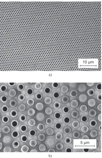
A SEM micrograph of an unilled silicon template with a regular hexagonal array of two-dimensional pores with the diameter of 2 µm and the inter-pore distance of 1 µm is shown in Figure 3a. After 20 iniltrations, as seen in Figure 3b, all of the pores have sidewalls covered by a PZT layer. The same sample is shown in a
cross-Figure 2. Interdigitated electrode structure: a), b) a schematic diagram – top and side view, c) an optical microscope image – top view.
Si substrate Ti/Au
SiO 2
b) a)
a)
b)
c)
Figure 4. SEM photograph of an ordered array of PZT mi-crotubes.
Figure 3. SEM images of macroporous silicon templates: a) unilled, b) iniltrated with PZT.
10 µm
500 µm
sectional view (Figure 4) after partial removal of the host Si matrix followed by thermal annealing at 750°C for 2 min in oxygen ambient. The result of an isotropic XeF2 reactive ion etching process is a regular array of free-standing microtubes anchored to the Si template only at the tube base. It is clear that the crystallized tubes are straight, nearly uniform, and completely discrete. It should be noted that the repeated vacuum iniltration allowed the PZT solution to deposit evenly at the bottom of the Si template pores.
In Figure 5, a SEM image shows a bunch of PZT tubes that were released completely from the template by soniication. Their hollow nature is demonstrated in Figure 5b, in which the open ends of individual tubes are depicted. A wall thickness can be estimated from the micrograph to about 400 nm. Because of pore proile irregularities caused natively by deep reactive ion etching of the Si templates, the rippled sidewalls are observed on microtubes close to the open ends.
X-ray diffraction analysis (Figure 6) demonstrates that the partially released PZT microtubes have perovskite phase after crystallization process at 750°C for 2 min in a rapid thermal annealer. The most intense relection at about 2θ = 70°and the weak relection
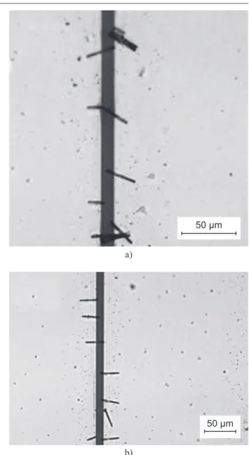
at 28,5° are due to the Si substrate. In addition to perovskite phase peaks, small Bragg relections of a pyrochlore phase are noticed in the XRD pattern. Kwok et al. [23] and Hamedi et al. [24] reported that formation of an intermediate pyrochlore or luorite phase during synthesis of lead-based ferroelectric ilms on substrates and free-standing PZT ilms, respectively, is kinetically favored over the perovskite phase. An additional second phase peak occurring at about 36° might be associated with the oxyluorides of Zr/Ti cations forming in the structure due to XeF2 gas phase etching of silicon. [10] Bharadwaja et al. [12] revealed that the luoride contamination can be minimized by mild boric acid treatment. As it has been proposed for the template-assisted processing of PbTiO3 tubes, an extension of annealing time would result in transformation of a metastable luorite phase into the perovskite phase. [8] In order to investigate the effect of annealing conditions on phase purity of PZT, different thermal budgets were used for crystallization of microtubes in the present work. However, heat treatment experiments at very high temperatures or extended times resulted in an irrever-sible damage of the tubes. The representative SEM images of broken microtubes are shown in Figure 7. While an annealing at a temperature of 800°C for 1 min caused buckling and melting of tubes (Figure 7a), the prolonged annealing at 750°C for 10 min resulted in their squeezing and joining (Figure 7b).
The results show that the vacuum iniltration tech- nique is a convenient method for producing the high aspect ratio ferroelectric microtube structures with tailored dimensions. Successive iniltrations of macro-porous Si templates under sub-atmospheric pressure facilitate uniform, thickness-tunable coating the inside of the Si template pores. On partial removal of the Si template by XeF2 gas phase treatment, it is possible to produce an ordered array of ceramic microtubes in which each tube is completely discrete. However, a)
b)
Figure 5. SEM image of the released tubes (a) and a hollow structure (b).
10 µm
1 µm
Figure 6. X-ray diffraction pattern of PZT micotubes anchored at the bottom of the Si template.
2θ (°)
In
te
n
s
it
y
(
c
p
s
)
20 0 50 100 150 200 150 200
control of the microstructure and phase com-position of free-standing PZT microtube structures remains a challenge. The processing conditions related to thermal budget and silicon removal process need to be further optimized.
Discrete microtubes were further manipulated by AC dielectrophoresis to position and align them at de-signed positions across the microelectrode array structure for fast future electrical characterization. Figures 8a and 8b show the results from an assembly experiment with a RMS (Vrms) voltage of 5 V (a square wave) driven at a frequency of 10 Hz. Results are shown for a pair of opposing electrodes with a 12 µm spacing. It is clear that the microtubes, which were deposited and oriented randomly between electrodes at the beginning, aligned in a uniform way and oriented preferentially perpendicular to the direction of the electrodes and parallel to each other. They appear to be randomly positioned along the electrode length and are mostly touching one of the two adjacent electrodes. An additional degree of tube alignment was achieved at a ixed voltage of 5 Vrms right before the complete evaporation of isopropanol by varying the frequency of square wave between 10 and 1 Hz. Field-induced oscillations of misaligned tubes
were observed as the frequency was rapidly decreased to 1 Hz. Then, with increasing frequency back to 10 Hz, one end of the tube was suddenly freed, rotated and re-trapped in his new location between the electrodes. We speculate that this effect might be due to the frequency dependent complex polarization factor that causes the changes not only in the dielectrophoretic force but also in the dielectrophoretic torque.
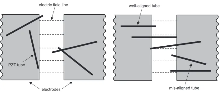
Figure 9 shows an illustration of translation and electrorotation of PZT tubes by dielectrophoresis, in-cluding the frequency-variation-induced enhancement in orientation of the tubes. It should be noted that the applied voltage of 3 Vrms was not suficiently large to cause an alignment of tubes. Only a few microtubes a)
a)
b)
b) Figure 7. SEM images of broken tubes after annealing: a) at
800°C for 1 min, b) at 750°C for 10 min.
Figure 8. Optical microscope images of the selected area of the electrode array with PZT microtubes assembled between the opposing electrodes with a 12 µm gap by applying a square wave signal of 5 Vrms and 10 Hz: a) before, and b) after rapid frequency variation in the range of 1-10 Hz.
5 µm
50 µm
a) time: 0-5 s, voltage: 0-5 Vrms, freq.: 10 Hz
At the beginning of the assembly process, the tubes move ran-domly. They can be trapped with the same probability at any point of the minima of the electric ield occurring between two parallel electrodes because the distribution of the electric ield is approximately equal along the electrode gaps.
c) time: 30-40 s, voltage: 5 Vrms, freq.: 1-10 Hz An enhancement in tube alignment was obtained by varying the frequency of the applied rectangular voltage. Upon the frequency variation between 1 and 10 Hz, misaligned tubes were observed to oscillate at one of the tube tip; while one end of the tube is pivoted, the other end was suddenly freed from its trapped position, rotated and inally re-trapped in a new, energetically more preferable position near the electrode edge with enhanced orientation. By repeating this process several times, the overall alignment of the tubes was improved before the complete evaporation of isopropanol.
b) time: 5-30 s, voltage: 5 Vrms, freq.: 10 Hz
The dielectrophoretic force acting on a microtube is proportional to the gradient of the electric ield. Because the gradient of the gradient of the electric ield drops off quickly with the distance from the electrode, the dielectrophoretic force acts primarily on microtubes that are close to the electrode gaps. As microtubes manipulated by the applied electric ield approach the electrode gap, large dielectric force induced by dipole-dipole interaction between the electrodes and tube tips leads to trapping of the tubes between the electrodes. A large fraction of the collected tubes are only in contact with one of the electrodes. They are mostly well aligned in the direction of the electric ield.
d) time: 40 s, voltage: 0, freq.: 0, IPA evaporated PZT microtubes assembled between two parallel rectangular shaped electrodes by dielectrophoresis.
Figure 9. Conceptual illustration of the frequency variation enhanced alignment.
electrodes PZT tube
electric field line
tube oscilations
mis-aligned tube well-aligned tube
near the centre of the electrode gap exhibited the aligned tendency. On the other side, increasing the electrode voltage from 5 Vrms to 15 Vrms at a ixed frequency of 10 Hz resulted in no tubes trapped in the electrode gaps. The tubes drifted away rather than stayed between the electrodes. This can be explained by increased moving speeds, vDEP ∞ ∇|E|2 [25], at higher electric ields.
The changes in alignment behavior caused by a variation in the amplitude and frequency of the applied square wave signal are due to forces that induce a translational movement and spatial reorientation of PZT microtubes across the microelectrode array structure and can be rationalized by considering the dielectrophoretic force model. [26] The time averaged dielectrophoretic force experienced by microtubes can be approximated through its irst dipole moment contribution as [21, 26]
(1) where r is the tube radius, l is the length of the tube, εm
is the absolute permittivity of the IPA medium, ∇|Erms|2
is the gradient of the square of the root-mean-square of the electric ield and Re[α→ ] is the real part of the com-plex effective polarizability or so called the Clausius-Mossotti factor. While the gradient of the ield is affected by both the geometry of the electrodes and the applied voltage, the Clausius-Mossotti factor is a function of the dielectric permittivities and conductivities of microtubes and suspending medium, as well as frequency of the applied AC ield:
(2) where ε* = ε – j (σ/ω) is the complex permittivity, ω is
the angular frequency of the applied electric ield, σ is the conductivity and j is the complex number (j = √-1). The subscripts t and m denote tube and medium, re-spectively.
The effective dipole moment approximation as-sumes that only a single dipole is induced on a particle [21]. The particle is assumed to be small compared to the characteristic length of the external electric ield, so that the gradient of the electric ield is essentially constant in the region surrounding the particle. In addition, it is assumed that the existence of the particle does not disturb its surrounding electric ield. For signiicantly nonuniform electric ields, higher order corrections are needed and multi-pole expansions are necessary. Aubry et al. [27] have used Distributed Lagrangian Method and Maxwell Stress Tensor approach to study the dielectrophoretic assembly of rigid spherical particles in an electric ield cage. They revealed that it is essential to solve the electric ield as a boundary value problem in order to obtain a solution for the dielectrophoretic force on objects with the size comparable to the gap size and captured in the vicinity of microelectrodes. Liu et al. [28] studied the range of validity of the dipole moment approximation and compared its accuracy with that of the Maxwell stress tensor calculation. They found that when
the characteristic length of the electric ield is larger than twice the diameter of the spherical particles, the dipole moment approximation estimates the dielectrophoretic force in the direction that is perpendicular to the electrode edges with the relative error within 3 %. As the characteristic length of the electric ield is increased, the accuracy of the dipole moment approximation improves. When the ratio of the particle length and the length scale of the electric ield is small, the presence of the particle introduces only a small disturbance in the electric ield and the dipole moment approximation provides an excellent approximation.
Following an Equation 1, the dielectrophoretic force is proportional to the gradient of electric ield, FDEP ∞ ∇E2. This means the higher the voltages at a ixed
frequency and the same electrode gaps are, the larger the gradients of the electric ield intensity and the greater the forces. In this experiment, the force experienced by microtubes at voltages below 5 Vrms was not enough to overcome the resistance forces (e.g., gravity, Brownian motion, viscous drag forces) in the solution. A majority of the tubes is loosely pulled and distributed randomly over the electrode array. Although, the tubes dispersed close to the electrodes were attracted to and seated in the electrode gaps by the applied 3-Vrms-square- wave signal. This can be explained by the fact that the gradient of the electric ield drops off quickly with distance from the electrode. With increasing the electrode voltage up to 5 Vrms, tubes are trapped between the interdigitated electrodes with improved alignment. The effect of the ield is anticipated, because the dielectrophoretic force increases with the squared values of the ield intensity and gradient, and the movement can proceed only when the effective force of long-range dielectrophoretic attraction between the tubes and electrodes becomes stronger than the Brownian motion or gravity. The force is directed along the gradient of electric ield intensity, which is not necessarily aligned with the applied electric ield. Raychaudhuri at al. [29] revealed that at low frequencies semiconductor nanowires followed the electric ield lines back to one of the two opposing electrodes, whereas at higher frequencies the wires were found to move in the direction of the electric ield gradient resulting in bridging of nanowires the electrode gap. Our results for ferroelectric PZT microtubes, which are observed only in contact with one of the biased microelectrodes, are consistent with those referred for the low frequency data in References 28 and 29.
The real part of the Claussius-Mossotti factor (Equation 2) gives the frequency dependence and the direction of the dielectrophoretic force. In the low and high frequency limits, the Re[α(ω)] can be simpliied as [30]
(3)
〈F
DEP〉 ≈ r
2lεm Re [α] ∇ |Erms|2
→ → →
α ω ε ω ε ω
ε ω
( )
=( )
−( )
( )
t m m * * *Re[ ( )]
When the conductivity and permittivity of sur-rounding medium, each dominating in the Hz-kHz and MHz-GHz range, respectively, exceeds that of the manipulated object, negative dielectrophoresis occurs. The objects are then directed away from regions of high ield intensities. Otherwise, positive forces lead to attraction. IPA has a high conductivity compared to the ferroelectric microtubes with much higher dielectric permittivity [12], and thus the PZT microtubes are expected to experience the negative dielectrophoresis in the low frequency region. Figure 8a shows that a majority of tubes is collected in the electrode gap, i.e. between opposing electrodes at a frequency of 10 Hz. This demonstrates the negative dielectrophoretic force with negative values of the effective polarizability factor that pushes tubes to regions corresponding to electric ield intensity minima. Crews et al. [31] identiied numerically these low-ield points exactly in the center between the two planar plate-like electrodes.
Inspection of the SEM image in Figure 8a reveals that aligned orientation induced by the 5 Vrms / 10 Hz square wave signal is somewhat random and even crossed in some regions. Liu et al. [28] proposed that thermal luctuation could randomize an orientation of a microtube oriented along the electric ield with one end ixed and the length loating. Another factor that could inluence the orientation of PZT tubes is a surface tension [32], an unevenness in the distribution of the strength of the dielectrophoretic force [33], or a variation in dielectrophoretic torque [34]. In general, the torque (TDEP) occurs in dielectrophoretic system
when the electric ield has a nonuniform phase, which means that there is a rotational component to the ield. Since the direction of the effective dipole lags behind the turning ield vector by a phase factor associated with the complex, frequency-dependent Clausius-Mossotti factor, dielectrophoretic torque applies on the tube and depends on the out-of-phase component of the dipole. [34] Y. Liu et al. [32] calculated using an analytical model that the torque will be always positive and a prolate spheroid will be always driven into alignment with the parallel electrodes if the gap size is larger than the length of the spheroid. The maximum dielectrophoretic torque was found for a tilt angle close to 30°. Nanowires longer than the distance between electrodes by two or more times were shown to be mis-oriented with respect to the microelectrode pair. These indings are in agreement with the achieved results, where several 30-µm-long PZT microtubes are not well oriented across the electrode array with 12 μm spacing.
The effect of a sinusoidal voltage on positioning and aligning of PZT tubes across the interdigitated electrode structure was found to be ineffective for the electric ield amplitudes and frequencies in the range of 1-15 Vrms and 10 Hz – 1 MHz, respectively, and needs to be further studied. Also, a design of more intricate
electrode structures providing spatially conined electric-ield proile with greater alignment and capture forces is necessary.
CONCLUSIONS
In summary, high aspect ratio ferroelectric tube structures made of PZT were successfully fabricated via template wetting technique. Using the repeated iniltration of a PZT liquid precursor into the pores of silicon templates under sub-atmospheric pressure, a uniform coating of the pore walls was achieved. On partial removal of the Si template, it was possible to produce a periodic array of free-standing ferroelectric tubes as mold replicas of a regular array of 2-D pores. The XRD and SEM analysis showed that thermal annealing at 750°C for 2 min in oxygen provides polycrystalline tubes of aspect ratio of about 20 with mainly perovskite structure. Therefore, the vacuum iniltration technique can be used as an alternative approach to other wafer-scale fabrication methods for producing ordered arrays of ferroelectric 1-D like structures as well as discrete microtubes with tailored dimensions.
The as-synthesized microtubes can be readily manipulated and so would facilitate the fabrication of more complicated structures for use in miniaturized electronic devices, including piezoelectric MEMS or NEMS actuators and sensors, and ferroelectric high-density FeRAM memories. To arrange tubes over large wafer areas, a simple and inexpensive method based on dielectrophoresis has been employed in the present work. The electric ield-assisted assembly of PZT microtubes between the parallel electrodes would allow, in irst step, for quick and simple creation of electrical connections at ambient conditions, and hence making a testing tube structure for rapid electrical characterization. Dielectrophoretic behavior study with different shapes, amplitudes and frequencies of the applied voltage revealed that a rectangular voltage of 5 Vrms and 10 Hz is the most effective in assembling PZT microtubes between the electrodes with 12-μm spacing. A frequency variation in the range of 1-10 Hz at ixed amplitude of the biasing voltage was found to improve the overall alignment of the tubes. These indings demonstrate that the dielectrophoretic technique has a great potential to control the alignment and placement of large numbers of PZT microtubes from solution onto pre-patterned electrodes using dielectrophoresis.
Acknowledgements
Agency through grant No APVV-0222-10 and COST MP0904 Action is gratefully acknowledged. The author appreciates valuable discussions on the processing and assembly of ferroelectric microtubes with Professor Susan Trolier-McKinstry and Professor Theresa Mayer and wishes to thank Dr. S. Bharadwaja and Dr. M. Li for their technical assistance within a Fulbright Scholarship Grant No. G-1-00005 at the Pennsylvania State University.
References 1. Scott J.F.: Science 315, 954 (2007). 2. Wang Z.L.: Adv. Mat. 19, 889 (2007).
3. Lieber C.M., Wang Z. L.: MRS Bull. 32, 99 (2007). 4. Bhat V.V., Madhusoodhana C.D., Umarji A.M.: Ferroelectr.
332, 97 (2006).
5. Naumov I.I., Bellaiche L., Fu H.: Nature 432, 737 (2004). 6. Robertson J.: Mat. Today 10, 36 (2007).
7. Morrison F.D., Ramsay L., Scott J.F.: J. Phys.: Cond. Matt. 15, L527 (2003).
8. Rørvik P.M., Tadanaga K., Tatsumisago M., Grande T., Einarsrud M.A.: J. Eur. Ceram. Soc. 29, 2575 (2009). 9. Luo Y., Szafraniak I., Zakharov N., Nagarajan N., Steinhart
M., Wehrspohn R., Wendorff J.H., Ramesh R., Alexe M.: Appl. Phys. Lett. 83, 440 (2003).
10. Bharadwaja S.S.N., Olszta M., Trolier-McKinstry S., Li X., Mayer T., Roozeboom F.: J. Am. Ceram. Soc. 89, 2695 (2006).
11. Kim J., Yang S.A., Choi Y.Ch., Han J.K., Jeong K.O., Yun Y.J., Kim D.J., Yang S.M., Yoon D., Cheong H., Chang K.S., Noh T.W., Bu S.D.: Nano Lett. 8, 1813 (2008). 12. Bharadwaja S.S.N., Moses P.J., Trolier-McKinstry S.,
Mayer T.S., Bettotti P., Pavesi L.: IEEE Trans. UFFC 57, 792 (2010).
13. Wang M.C.P., Gates B.D.: Mat. Today 12, 34 (2009).
14. Pohl H.A.: J. Appl. Phys. 22, 869 (1951). 15. Pohl H.A.: J. Appl. Phys. 29, 1182 (1958).
16. Smith P.A., Nordquist Ch.D., Jackson T.N., Mayer T.S., Martin B.R., Mbindyo J., Mallouk T.E.: Appl. Phys. Lett. 77, 1399 (2000).
17. Krupke R., Hendrich F., Lohneysen H.V., Kappes M. M.: Science 301, 344 (2003).
18. Lee S.Y., Kim T.H., Suh D.I., Cho N.K., Seong H.K., Jung S.W., Choi H.J., Lee S.K.: Chem. Phys. Lett. 427, 107 (2006).
19. Lee S.Y., Umar A., Suh D.I., Park J.E., Hahn Y.B., Ahn J.Y., Lee S.K.: Physica E 40, 866 (2008).
20. Kumar S., Yoon S.H., Kim G.H.: Curr. Appl. Phys. 9, 101 (2009).
21. Jones T.B.: Electromechanics of Particles, Cambridge University Press, New York, 1995.
22. Wolf R.A., Trolier-McKinstry S.: J. Appl. Phys. 95, 1397 (2004).
23. Kwok C.K., Desu S.B.: Appl. Phys. Lett. 60, 1430 (1992). 24. Hamedi L.H., Guilloux-Viry M., Perrin A., Li Z.Z., Raffy
H.: J. Solid State Chem. 158, 40 (2001).
25. Green N.G., Ramos A., Morgan H.: J. Phys. D: Appl. Phys. 33, 632 (2000).
26. Pohl H.A.: Dielectrophoresis, Cambridge University Press, Cambridge, 1978.
27. Aubry N., Singh P.: Europhys. Lett. 74, 623 (2006). 28. Liu Y., Chung J.H., Liu W.K., Ruoff R.S.: J. Phys. Chem. B
110, 14098 (2006).
29. Raychaudhuri S., Dayeh S.A., Wang D., Yu E.T.: Nano Lett. 9, 2260 (2009).
30. Dimaki M., Bøggild P.: Nanotechnology 15, 1 (2004). 31. Crews N., Darabi J., Voglewede P., Guo F., Bayoumi A.:
Sens. Actuators B 125, 672 (2007).
32. Liu W.J., Zhang J., Wan L.J., Jiang K.W., Tao B.R., Li H.L., Gong W.L., Tang X.D.: Sens. Actuators B 133, 664 (2008). 33. Xu D., Subramanian A., Dong L., Nelson B.J.: IEEE Trans.
Nanotech. 8, 449 (2009).