JOURNAL OF NANO- AND ELECTRONIC PHYSICS А А - А
Vol. 5 No 4, 04049(3pp) (2013) 5№ 4, 04049(3cc) (2013)
2077-6772/2013/5(4)04049(3) 04049-1 2013 Sumy State University
Influence of Doping of Titanium Dioxide by Zirconium and Niobium on its Morphology
L.M. Humeniuk, I.M. Budzulyak, R.V. Ilnytskyy
Vasyl Stefanyk Precarpathian National University, 57, Shevchenka Str., 76000 Ivano-Frankivsk, Ukraine
(Received 16 October 2013; published online 31 January 2014)
Structure porosity and specific surface area of undoped and doped nanodispersed titanium dioxide with Zr, Nb was investigated. The porous structure of TiO2 is caused by its intervals between nanoparticles and their agglomerates. Surface morphology of obtained materials was determined by isotherms of nitrogen adsorption-desorption. Specific surface area of nanodispersed titanium dioxide, according to the results, consists 182 m2/g. It was found, that during doping of titanium dioxide with zirconium comparing to origin TiO2 specific surface increases in 30 %, and for niobium-doped decreases in 20 %. Pore-size distribution for TiO2<Nb> correspond to the value of 10-15 nm.
Keywords: Doping, Titanium dioxide, Specific surface.
PACS number: 68.47.Gh
1. INTRODUCTION
Titanium dioxide, especially nanosized TiO2, is a promising material in nowadays technologies [1]. TiO2 obtaining in different polymorphs (anatase, rutile and brookite) and its modification is a quite topical at this time because it has large specific surface and structure which is capable for intercalation process. Modification of TiO2 is mostly done by doping with admixture, which change both the crystal structure and its morphology [2]. This paper presents the study of the pore structure of origin titanium dioxide and its change caused by chemi-cal admixture of transition metals Nb and Zr. We have found [3, 4], that modified in such a way TiO2 has a num-ber of advantages, including its larger surface area, smaller particles and better thermal stability [5-7], which is crucial fact for its use as an electrode material [8].
The porous structure of TiO2 is caused by its granu-lar structure and it is the intervals between primary and secondary (agglomerates) particles. SEM image of the surface material of TiO2, TiO2Zr, TiO2Nb indicates on a slight increase of spherical grains for TiO2Nb [3].
According to data [9], niobium-doping at concentra-tion of 1 %, 3 %, 5 % causes to decrease of TiO2 parti-cles for anatase and their increase for rutile. Interact-ing with each other oxides TiO2 and ZrO2 form a solid solution ZrxTi1 – xO2 with large surface area, high thermal stability and mechanical strength [10].
2. EXPERIMENTAL DETAILS
Surface morphology of doped titanium dioxide which main structure is anatase was determined by isotherms of nitrogen adsorption-desorption at a tem-perature T 77 K on the device Quantachrome Auto-sorb (Nova 2200e). Calculation of the specific area and determination of the pore distribution were carried out automatically using computer programs.
Samples were degased in a vacuum chamber with a residual pressure of ~ 1.3 Pa at 373 K for 17 hours. The total pore volume was calculated by volume of adsorbed nitrogen according to desorption isotherm. The method of BJH (Barrett-Joyner-Halendy) was used to mine the porosity. The specific surface area was deter-mined by multipoint method.
3. RESULTS AND DISCUSSION
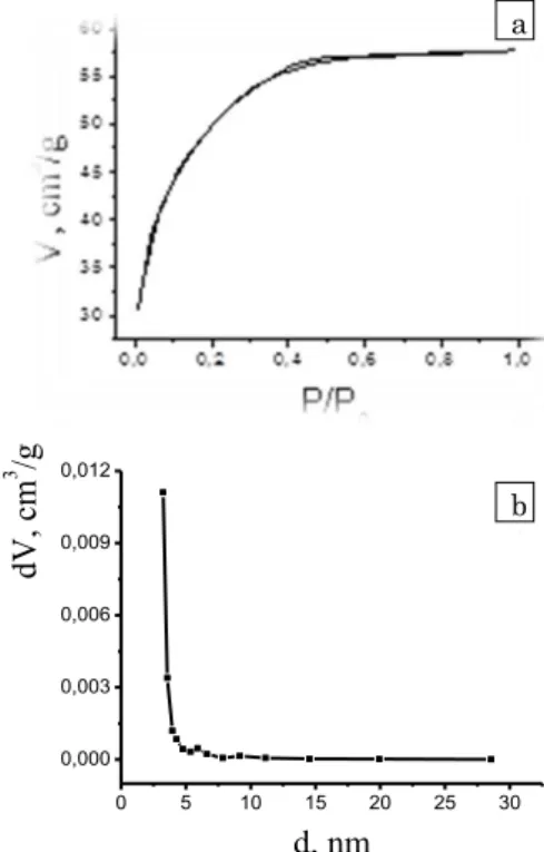
Obtained titanium dioxide by sol-gel technology is nano dispersed with an average particle size of 10 nm. Zirconium and niobium concentration in TiO2 was 20 mol % in molar mass, but impurity phases were not observed on X-ray diffractograms [3, 4], indicating its complete solubility in the structure of the main material. Fig. 1 shows the adsorption-desorption isotherms of nitrogen (a) and pore-size distributions (b) defined by BJH method for the origin TiO2. Isotherm (Fig. 1a) is characterized by two hysteresis loops at relative pres-sures 0.4 P/P0 0.6 and at 0.05 P/P0 0.1.
0 5 10 15 20 25 30
0,000 0,003 0,006 0,009 0,012
b
dV,
cm
3
/g
d, nm
Fig. 1– N2 isotherms (a) and pore-size distribution (b) for origin TiO2
This is a Type I isotherm according to the IUPAC clas-sification, which is inherent for microporous substances and describes the material as a matter of uniform surface, which is consistent with the SEM image, where by the surface of TiO2 consists of uniform spherical nanoparticles.
a
b
L. HUMENIUK, I. BUDZULYAK, R. ILNYTSKYY J. Nano- Electron. Phys. 5, 04049 (2013)
04049-2 Maximum pore-size distribution for TiO2 (Fig. 1b) cor-responds to the value of 3 nm. According to the definition of pore size classification this value for 2 corresponds to micropores as consistent with the obtained isotherm on Fig. 1a.
For niobium-doped titanium dioxide nitrogen iso-therm is Type V, which is typical for micro- and mesopo-rous materials and indicates a significant pore increase after doping.
One explanation for this phenomenon is the increase of nanoparticles surface area or their agglomeration and thus increases of the relative part of the pores with larger size. The value of pore-size distribution for TiO2Nb is presented in Fig. 2b.
Comparing with the preceding distribution pore-size distribution in the 10-15 nm region is observed, which corresponds to mesopores, although there are mi-cropores too.
0,0 0,2 0,4 0,6 0,8 1,0 0
50 100 150 200 250
a
V,
cm
3
/g
P/P
00 5 10 15 20 25 30 35 0,00
0,01
0,02
b
dV,
cm
3
/g
d, nm
Fig. 2– N2 isotherms (a) and pore-size distribution for TiO2 doped with Nb (b)
For zirconium-doped titanium dioxide (Fig. 3) iso-therm indicates an increase in the porosity of the mate-rial compared to the origin TiO2 and Nb-doped TiO2. For this case it is a type III isotherm, which is close to the V type. Hysteresis loop (Fig. 3a) the same as for previous material at pressures of 0.8 P/P0 0.98 cor-responds to filling with nitrogen of major structural pores and mesopores between gaps of agglomerated (secondary) particles. According to Fig. 3b it is clear that the maximum of distribution is for the micropores with the size of 3 nm as to the origin TiO2.
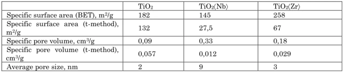
Thus, doping changes the morphology of titanium dioxide, increasing the pore size, especially for the case of TiO2Nb. Table1 shows the parameters of TiO2 po-rous structure.
Especially it is very important that compared with the origin titanium dioxide and TiO2Nb specific sur-face determined by the method of BET and t-method TiO2Zr is the largest and corresponds to Fig. 3b.
0,0 0,2 0,4 0,6 0,8 1,0 20
40 60 80 100 120 140
a
V,
cm
3
/g
P/P
0
5 10 15 20 25 30 35 0,00
0,02 0,04 0,06 0,08
b
dV,
cm
3
/g
d, nm
Fig. 3– N2 isotherms of nitrogen (a) and pore size distribu-tion for Zr-doped TiO2 (b)
Table 1– Characterization of surface and pore structure of nano dispersed TiO2
TiO2 TiO2Nb TiO2Zr
Specific surface area ( )б m2/g 182 145 258 Specific surface area (t-method),
m2/g 132 27,5 67
Specific pore volume, cm3/g 0,09 0,33 0,18
Specific pore volume (t-method),
cm3/g 0,057 0,012 0,029
Average pore size, nm 2 9 3
a
a
b
b
b
a
b
b
INFLUENCE OF DOPING OF TITANIUM DIOXIDE ZIRCONIUM… J. Nano- Electron. Phys.5, 04049 (2013)
04049-3
4. CONCLUSIONS
Pore size and specific surface area of nanodispersed origin, zirconium-and niobium-doped titanium dioxide have been calculated by BJH and BET methods.
It was found that during zirconium-doping specific
surface area increases significantly to 258 m2/g rela-tively to the value for the origin TiO2 and decreases to 145 m2/g for niobium-doped TiO2. Micropores are pre-dominant, especially for TiO2 and TiO2Zr. For TiO2Nb maximum pore size distribution is 10-15 nm.
В и і и и і іє і и іє і і
г г б Іг г б г г І
а а а а е е гВг е а а, г Ше е а, км, мл000
г а - а , а а
в
Zr i Nbг б TiO2 є в
г Ш - в
г
2 ( ~же )б жнз 2д г б б в
є TiO2 є ие%б
є є зе%г є в
є же-15 г
К і п б б г
В и и и и и и и и и и и и и и
г г б Иг г б г гИ
а а а а е е г Вг е а а, г Ше е а, км, мл000
г а - а , а а
И в
Zr Nbг б TiO2
г
- г в
2 ( ~же )б в
б жнз 2д г б б
TiO2 ие%б
– зе%г в
же-15 г
К ы п б б г
REFERENCES
1. I.F. Mironyuk, V.O. Kotsyubynskyy, B.K. Ostafiychuk,
Synthesis, structure and electrochemical properties of oxide nanomaterials: a monograph (Ivano-Frankivsk: Vasyl Stefanyk Precarpathian National University: 2011). 2. A. Zaleska, Recent patents of engineering 2, 57 (2008). 3. L.M. Humeniuk, I.I. Grigorchak, I.M. Budzulyak,
R.V. Ilnytskyy, Phys. Chem. Solids 13, 685 (2012). 4. I.M. Budzulyak, L.M. Humeniuk, R.V. Ilnytsky,
P.I. Yaremiy, Visnuk of the Precarpathian University. Chemistry 2, 94 (2012).
5. E. Sotter, X. Vilanova, E. Llobet, M. Stankova, X. Correig,
J. Optoelectron. Adv. M.7, 1395 (2005).
6. M.V. Koudriachova, N.M. Harrison, J. Mater. Chem. 16, 1973(2006).
7. N. Tsvetkov, L. Larina, O. Syevaleevskiy, Energy Environ. Sci. 4, 1480 (2011).
8. A.L. Rahima, The University of Western Ontario London, Ontario, Canada, 265 (2008).