CPD
7, 2863–2891, 2011Modeling of stability of gas hydrates
J. Majorowicz et al.
Title Page
Abstract Introduction
Conclusions References
Tables Figures
◭ ◮
◭ ◮
Back Close
Full Screen / Esc
Printer-friendly Version Interactive Discussion
Discussion
P
a
per
|
Dis
cussion
P
a
per
|
Discussion
P
a
per
|
Discussio
n
P
a
per
|
Clim. Past Discuss., 7, 2863–2891, 2011 www.clim-past-discuss.net/7/2863/2011/ doi:10.5194/cpd-7-2863-2011
© Author(s) 2011. CC Attribution 3.0 License.
Climate of the Past Discussions
This discussion paper is/has been under review for the journal Climate of the Past (CP). Please refer to the corresponding final paper in CP if available.
Modeling of stability of gas hydrates
under permafrost in an environment of
surface climatic change – terrestrial case,
Beaufort-Mackenzie basin, Canada
J. Majorowicz1, J. ˇSafanda2, and K. Osadetz3
1
Department of Physics, University of Alberta and NGC 105 Carlson Close Edmonton, AB, T6R 2J8, Canada
2
Institute of Geophysics, Czech Academy of Sciences, 141-31 Praha 4, Czech Republic
3
Geological Survey of Canada 3303 – 33rd St. NW Calgary, AB, T2L2A7, Canada
Received: 15 August 2011 – Accepted: 5 September 2011 – Published: 15 September 2011
Correspondence to: J. Majorowicz ([email protected])
CPD
7, 2863–2891, 2011Modeling of stability of gas hydrates
J. Majorowicz et al.
Title Page
Abstract Introduction
Conclusions References
Tables Figures
◭ ◮
◭ ◮
Back Close
Full Screen / Esc
Printer-friendly Version Interactive Discussion
Discussion
P
a
per
|
Dis
cussion
P
a
per
|
Discussion
P
a
per
|
Discussio
n
P
a
per
|
Abstract
Modeling of the onset of permafrost formation and succeeding gas hydrate formation in the changing surface temperature environment has been done for the Beaufort-Mackenzie Basin (BMB). Numerical 1-D modeling is constrained by deep heat flow from deep well bottom hole temperatures, deep conductivity, present permafrost
thick-5
ness and thickness of Type I gas hydrates. Latent heat effects were applied to the
model for the entire ice bearing permafrost and Type I hydrate intervals. Modeling for a set of surface temperature forcing during the glacial-interglacial history including the last 14 Myr was performed. Two scenarios of gas formation were considered; case 1: formation of gas hydrate from gas entrapped under deep geological seals and case 2:
10
formation of gas hydrate from gas in a free pore space simultaneously with permafrost formation. In case 1, gas hydrates could have formed at a depth of about 0.9 km only some 1 Myr ago. In case 2, the first gas hydrate formed in the depth range of 290– 300 m shortly after 6 Myr ago when the GST dropped from −4.5◦C to −5.5.◦C. The gas hydrate layer started to expand both downward and upward subsequently. These
15
models show that the gas hydrate zone, while thinning persists under the thick body of BMB permafrost through the current interglacial warming periods.
1 Introduction
The attempt to model the onset of ice bearing permafrost (IBP) formation, the formation of petroleum gas hydrate (GH) and modeling for the more detailed Holocene
tempera-20
ture history requires knowledge of the surface temperature forcing environment. This needs to be derived from sources sometimes distant from the study area of the Cana-dian Arctic and specifically the Beaufort Mackenzie Basin (BMB) area where very thick GHs are located currently.
Recent results of the analysis of the Holocene-Pleistocene temperature history using
25
CPD
7, 2863–2891, 2011Modeling of stability of gas hydrates
J. Majorowicz et al.
Title Page
Abstract Introduction
Conclusions References
Tables Figures
◭ ◮
◭ ◮
Back Close
Full Screen / Esc
Printer-friendly Version Interactive Discussion
Discussion
P
a
per
|
Dis
cussion
P
a
per
|
Discussion
P
a
per
|
Discussio
n
P
a
per
|
600 k yr by Majorowicz et al. (2008) showed that GH can be stable through interglacial intervals despite large variations in surface temperatures due to the buffering effect of
the IBP and the retardation of GH dissociation due to latent heat effects. The present
paper focuses on the analysis of the origin, growth and persistence of the GH and IBP layers. Understanding of formation and persistence of sub-permafrost GH
accumula-5
tions should help us to determine if a geological natural gas resource model can be formulated. Our analysis will use the characteristics of IBP and GH response to vari-ations of surface temperature history, to simultaneously constrain the models of past environments that led to the initiation, growth and persistence of the linked occurrences of both IBP and GH accumulations in the subsurface of the Canadian Arctic. The work
10
will also address the risks posed by global and regional temperature change, as well as will provide a tool that will assist the appraisal of risks related to surface imposed changes on the GH layer. In order to model conditions for the IBP formation due to cooling of the surface and following GH formation considering latent heat “delay” ef-fects (due to deeper formation conditions) we need to know surface conditions in the
15
past.
To understand better the formation and history of petroleum GHs in terrestrial IBP regions we have performed numerical modeling of the surface forcing due to general cooling trend started in late Miocene and more detailed glacial-interglacial history. Per-sistent GH layers in a terrestrial environment of thick IBP in cold regions sequester
20
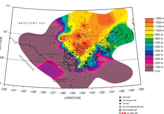
methane and impede its migration into the atmosphere. The Mallik site in the Macken-zie Delta is an excellent example of such GH deposits situated in the large area of deep GH Type I stability in the onshore and offshore (Fig. 1) under continental and
continental relic IBP (accumulated during the Pleistocene marine low-stand prior to the Holocene sea level rise). More detailed descriptions can be found in a collection of
25
CPD
7, 2863–2891, 2011Modeling of stability of gas hydrates
J. Majorowicz et al.
Title Page
Abstract Introduction
Conclusions References
Tables Figures
◭ ◮
◭ ◮
Back Close
Full Screen / Esc
Printer-friendly Version Interactive Discussion
Discussion
P
a
per
|
Dis
cussion
P
a
per
|
Discussion
P
a
per
|
Discussio
n
P
a
per
|
We model the onset of permafrost formation and subsequent GH formation in the changing surface temperature environment for the Beaufort-Mackenzie (BMB), Fig. 1. We also model terrestrial BMB GH thickness variations below an ice-bearing IBP layer in response to past surface temperature changes onshore and offshore in BMB using
a 1-D thermal model that assumes no water or gas flow.
5
2 Assumed Surface temperature history
Our evidence for past temperatures comes mainly from isotopic considerations (es-pecially δ18O). Our models of surface forcing of temperature are based on several sources (Muller and MacDonald, 2000; Frakes et al., 1992; Taylor et al., 2005; Inter-governmental Panel on Climate Change, 2007).
10
The analysis of the paleoclimatic data for the Phanerozoic and specifically for the last tens of millions years (Myr) from the above sources and ones in the References show:
Sixty-five to one hundred Myr ago average global temperatures were the highest during the last∼200 Myr (Wikipedia.org, 2008). This obviously prevented the
forma-15
tion of large scale ice sheet. Forests extended all the way to the poles. Temperature also peaked 50–52 Myr ago, when atmospheric CO2ranged 1125–3000 parts per
mil-lion. By 20 Myr ago, CO2 dropped to about 400 ppm (Polsson, 2007; Lawrence, 2006;
Wikipedia.org, 2008).
Following the Paleocene to early Eocene peak warming the climate cooled
vari-20
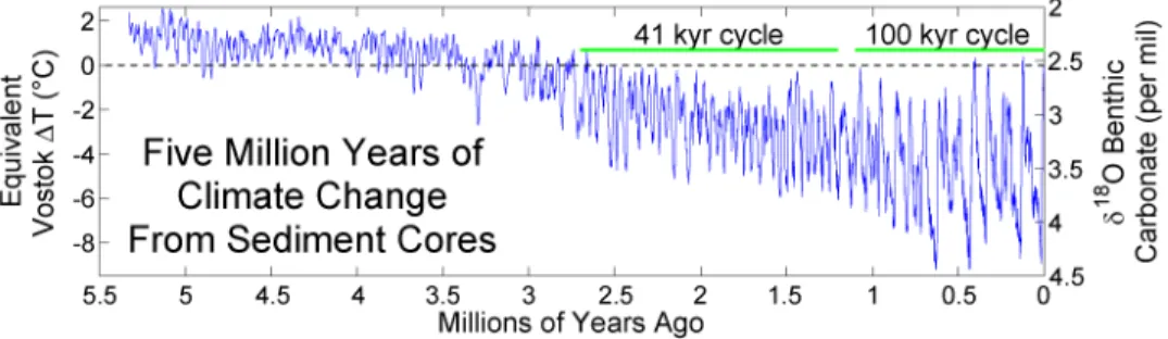
ably towards the Pleistocene glacial environment (Wikipedia.org, 2008). However, 3 to 6 Myr ago, globally averaged temperatures (Wikipedia.org, 2008) (Fig. 2) were still higher than today with surface temperature at poles higher than present temperatures. The Northern Hemisphere likely had no continental glaciers [Muller and MacDonald, 2000; Frakes et al., 1992; Lawrence, 2006].
25
CPD
7, 2863–2891, 2011Modeling of stability of gas hydrates
J. Majorowicz et al.
Title Page
Abstract Introduction
Conclusions References
Tables Figures
◭ ◮
◭ ◮
Back Close
Full Screen / Esc
Printer-friendly Version Interactive Discussion
Discussion
P
a
per
|
Dis
cussion
P
a
per
|
Discussion
P
a
per
|
Discussio
n
P
a
per
|
resulted in cycles of glacials and interglacials within a gradually deepening ice age. The growth and retreat of continental ice sheets in the Northern Hemisphere occurred at 2 frequencies; 41 kyr and 100 kyr (Fig. 2). The gradual intensification of this ice age over the last 3 Myr has been associated with declining concentrations of the CO2which
partly influences this change in temperatures. El Nino was continual rather than
inter-5
mittent until 3 million yr (Myr) ago. Significant amplification of the response of climate to orbital forcing began 3 Myr ago, resulting in drastic oscillations between ice ages and warmer periods over the past 1 Myr (Fig. 2).
3 P-T time envelope and formation of permafrost and gas hydrate – preliminary
considerations
10
In order to simulate the IBP and GH formation, we have constructed the general model of the surface temperature forcing history for the last 14 Myr (Figs. 4–5) based on temperature history given in (Muller and MacDonald, 2002; Frakes et al., 1992; Wikipedia.org, 2003). The most recent surface climate history for the end of the Wis-consinan and Holocene is after Taylor et al. (2005). If the equivalent Vostok∆T
temper-15
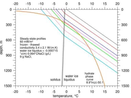
ature of 0◦C indicated for the present time (Fig. 2) corresponds to the present ground surface temperature of−6◦C at Mallik Richards I. Beaufort-Mackenzie basin, Canada (Fig. 1), then during the period 6–3.5 Myr ago it corresponds to ground surface tem-perature (GST) oscillations at Mallik between −6◦C and −4◦C. The range of GSTs between−6◦C and−4◦C is critical for GH formation as shown in preliminary test for
20
the steady-state in Fig. 3. The geotherm coresponding to the GST of−5◦C (Fig. 3) approaches the GH phase curve from above at the depth of about 300 m. According to it, the GH could not have formed when the GST was higher than−5◦C. Before 6 Myr ago the climate was even warmer, which means that the first GH deposits might have formed around 6 Myr or later, compared to the onset time of 14 Myr ago for the IBP
25
CPD
7, 2863–2891, 2011Modeling of stability of gas hydrates
J. Majorowicz et al.
Title Page
Abstract Introduction
Conclusions References
Tables Figures
◭ ◮
◭ ◮
Back Close
Full Screen / Esc
Printer-friendly Version Interactive Discussion
Discussion
P
a
per
|
Dis
cussion
P
a
per
|
Discussion
P
a
per
|
Discussio
n
P
a
per
|
formation.The equilibrium IBP thickness is some 250 m for a GST of−5◦C. This means that GH could have formed immediately below the IBP base. Because the geotherm and the phase curve are nearly parallel in this range of p-T, even a small downward shift of the geotherm means a large broadening of the zone with the p-T conditions favorable for GH formation.
5
Further surface cooling below−5◦C caused the IBP base to descend into the layer already occupied by GH. For 30 % porosity and 60 % GH saturation, the remaining water available to freeze occupied not 30 %, but only 12 % of the whole volume and the latent heat released by its freezing was 2.5 times smaller than in the IBP interval above the GH. The question is, “what had happened with the methane in the uppermost
10
300 m, if any gas was initially collected under the IBP?”
4 Method
Nomenclature
A: Rate of heat generation [W m−3] Cv: Volumetric heat capacity [J (m
−3
·K)]
K: Thermal conductivity [W m K−1]
L: Latent heat in water/ice [J kg−1]
T: Temperature [◦C]
t: Time [s]
z: Depth [m]
P: Density [kg m−3]
Φ: Fraction of the total volume occupied by ice/gas hydrate and other phases
Myr: million yr
CPD
7, 2863–2891, 2011Modeling of stability of gas hydrates
J. Majorowicz et al.
Title Page
Abstract Introduction
Conclusions References
Tables Figures
◭ ◮
◭ ◮
Back Close
Full Screen / Esc
Printer-friendly Version Interactive Discussion
Discussion
P
a
per
|
Dis
cussion
P
a
per
|
Discussion
P
a
per
|
Discussio
n
P
a
per
|
Solving the transient heat conduction equation gives the temporally dependent sub-surface temperature change in response to sub-surface forcing:
Cv∂T/∂t=∂[K(∂T/∂z)]/∂z+A (1)
whereT is the temperature, K is the thermal conductivity, Cv is the volumetric heat
capacity,Ais the rate of heat generation per unit volume, z is the depth, andt is the
5
time in a one-dimensional, layered geothermal model. We employed a computer code to simulated temporal subsurface temperature changes in response to surface forcing by Safanda et al. (2004). Within the model Eq. (1) is solved numerically by an im-plicit finite-difference method similar to that described by Galushkin (1997). The upper
boundary condition is the temporally varying GST and the lower boundary condition
10
is a constant heat flow density at 15 km depth. The depth grid steps are: 2, 5, 10, 50, 100, 250 and 500 m in the depth layers at 0–100, 100–1500, 1500–2000, 2000– 2500, 2500–5000, 5000–10 000, 10 000–15 000 m, respectively. Time steps vary be-tween 0.5 to 50 yr, depending on the amplitude of GST changes. The finite-difference
scheme of Eq. (1) on the depth and time grids ..zk−1,zk ,zk+1,... and ...tn,tn +1
,...,
15
respectively, has a form:
Cv,kn (Tn+1 k −T
n k)/(t
n+1
−tn)=2Kn k+1(T
n+1
k+1−T n+1
k )/[∆zk+1(∆zk+ ∆zk+1)]
−2Kkn(Tkn+1−Tkn−+11)/[∆zk(∆zk+ ∆zk+1)]+Ak (2)
where the subscriptk and the superscript ndenote values at thekth depth step and thenth time step, respectively;∆zk=zk–zk−1;Kn
k+1= ∆zk+1/[∫zk +1 zk dz/k
n
(z)].
20
This difference scheme, together with the upper and lower boundary conditions lead
to a system of difference equations for unknown valuesTn+1 k−1, T
n+1 k , T
n+1
k+1 within a
tri-diagonal matrix, which was solved by the forward method of Peaceman and Rach-ford (1955).
To estimate effective thermal conductivity values and volumetric heat capacity, it was
25
CPD
7, 2863–2891, 2011Modeling of stability of gas hydrates
J. Majorowicz et al.
Title Page
Abstract Introduction
Conclusions References
Tables Figures
◭ ◮
◭ ◮
Back Close
Full Screen / Esc
Printer-friendly Version Interactive Discussion
Discussion
P
a
per
|
Dis
cussion
P
a
per
|
Discussion
P
a
per
|
Discussio
n
P
a
per
|
fractions Galushkin (1997) and Nixon (1986). A consumption or release of the latent heat, L,in water/ice (334 kJ kg−1) and GH (430 kJ kg−1) accompanying either thawing or freezing was included. The effects of interstitial ice and GH were accounted for using
apparent heat capacity according to Carslaw and Jaeger (1959), when the volumetric heat capacity is increased in the depth sections of the model where the thawing and
5
freezing occurs, i.e. where the temperature is within the thawing rangebetween the temperature of solidusTS, and liquidus,TL, at the actual simulation time step.
The liquidus and solidus temperatures of water/ice and GH are depth and hydro-static pressure dependent (Galushkin, 1997) and solidus temperatures were 0.2◦C lower than liquidus temperatures. A contribution to the heat capacity from the latent
10
heat=ρΦL/(TL−TS) was considered, whereρis the density of either ice or GH andΦ
is a fraction of the total volume occupied by these phases. In the IBP zone we infer the 30 % rock matrix porosity to be fully occupied by water at temperatures aboveTL,
and by ice at temperatures belowTS. Within the GH stability zone the GH saturation in
matrix porosity was inferred to be 60 %. The salt concentration 9 g L−1was considered
15
constant with depth and the p-T phase curves were adjusted to this value.
Numerical code performance was tested by comparing model results against the analytical solidification problem solution Carslaw and Jaeger (1959).The error estimate for the IBP and GH numerical simulations is of the order of tenths of degree C. A similar error range was estimated by halving the time and/or depth steps.
20
Our model uses deep heat flow, thermal conductivity, present IBP, Type I GH thick-nesses and a surface melting temperature (−0.576◦C) that considers groundwater salinities (9 g L−1). It employs latent heat effects throughout the IBP and GH layers,
which improves upon previous models Taylor (2005). The models are constrained by deep heat flow from bottom hole temperatures determined from deep wells Majorowicz
25
CPD
7, 2863–2891, 2011Modeling of stability of gas hydrates
J. Majorowicz et al.
Title Page
Abstract Introduction
Conclusions References
Tables Figures
◭ ◮
◭ ◮
Back Close
Full Screen / Esc
Printer-friendly Version Interactive Discussion
Discussion
P
a
per
|
Dis
cussion
P
a
per
|
Discussion
P
a
per
|
Discussio
n
P
a
per
|
according to Sloan (1998), (Fig. 3). Previously published models have considered only a thin layer using a constant dissociation temperature Taylor (2005).
In simulating the temporal subsurface changes in models with vertically separated occurrence of IBP and GH, a consumption/release of the latent heat during de-cay/formation of IBP or GH was considered separately. This means that in IBP zone,
5
only the latent heat and p-T phase curve of water ice were taken into account, and in the GH zone only latent heat and p-T phase curve of the GH is considered. The division into IBP and GH zones was prescribed in the model explicitly.
The above conditions may not be appropriate in models of possible simultaneous IBP and GH occurrence. In such cases it is prescribed at each depth point, which
10
fraction of the pore space can be occupied by water ice and which by GH. Then the code checks independently the p-T conditions for IBP and for GH in each depth point, in each time step and adjusts the volumetric heat capacity to the actual temperature at a given depth Carslaw and Jaeger (1959). For example, in the Mallik case, where a porosity of 30 % was assumed, the prescribed pore fraction of GH in the uppermost
15
250 m was zero and that of IBP 100 %, because as the preliminary calculations had shown, IBP forms prior to hydrate. On the contrary, below 250 m the GH forms first. For the 60 % saturation of the pore space by GH this means that the ratio of pore fractions occupied by GH and IBP is 60: 40 at this depth.
5 Model for the 14 Myr history of surface temperature change – results
20
We have simulated the downward propagation of the surface warming and cooling considering the cyclical glacial and interglacial models for the eastern Richards Island location where Malik well was drilled for hydrate (Fig. 1).
The dependence of the thermal conductivity on water/ice content and the specific heat of the rock section on the porosity and the proportion of interstitial water and iceare
25
important. Accounting for the effect of the latent heat necessary to thaw the interstitial
CPD
7, 2863–2891, 2011Modeling of stability of gas hydrates
J. Majorowicz et al.
Title Page
Abstract Introduction
Conclusions References
Tables Figures
◭ ◮
◭ ◮
Back Close
Full Screen / Esc
Printer-friendly Version Interactive Discussion
Discussion
P
a
per
|
Dis
cussion
P
a
per
|
Discussion
P
a
per
|
Discussio
n
P
a
per
|
would proceed much faster.
Individual computational models use the characteristics of IBP and GH formation and dissipation, as functions of temperature history, constrained by present temperature observations and current IBP and GH layer thicknesses.
All models account for latent heat by means of the apparent specific heat, which is
5
a standard treatment. The model also considers diffusive heat flow related to
surface-subsurface coupling.
There was a warm period (25 to 15 Myr ago) with maybe no IBP in Mallik. According to our model, the surface temperature in Mallik dropped below 0◦C 14 Myr ago, which initiated the IBP formation. We have used a stepwise approximation of the surface
10
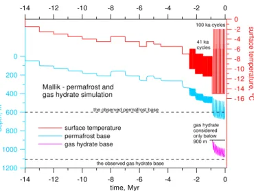
temperature with a length of the step 1 Myr between 14 and 6 Myr ago and 0.5 Myr between 6 and 2.5 Myr. From 2.5 Myr ago we consider the 41 ka cycle and from the 0.9 Myr the 100 ka cycle.
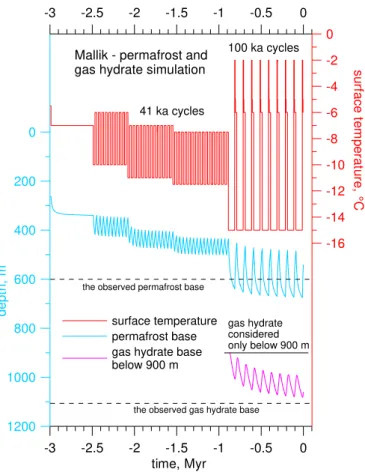
Case 1 – Gas hydrate formation controlled by the geological gas entrapment conditions
15
In Case 1 (Fig. 4) we allow occurrence of GH only in the geologically confined area under a geologically impermeable seal.
This is a probable situation for case of the Beaufort-Mackenzie (BMB) GHs as shown by stratigraphic sections in the Mallik boreholes Majorowicz et al. (2008). At Mallik, the interbedded character of the GH bearing strata indicates a lithologic control on
20
GH occurrence. GH layers occur in coarse-grained sandstone beds separated by thin non-hydrate-bearing, fine-grained siltstone and claystone beds. The gas and GH at Mallik appears to be entrapped in association with the diastrophic structure. The fault bounding the structure is the likely conduit for migration of the gas into the GH stability zone (GHSZ). Methane isotopic compositions of 12 GH samples averaged −42.7 %
25
and clearly indicate a thermogenic source according to Lorenson et al. (2004).
CPD
7, 2863–2891, 2011Modeling of stability of gas hydrates
J. Majorowicz et al.
Title Page
Abstract Introduction
Conclusions References
Tables Figures
◭ ◮
◭ ◮
Back Close
Full Screen / Esc
Printer-friendly Version Interactive Discussion
Discussion
P
a
per
|
Dis
cussion
P
a
per
|
Discussion
P
a
per
|
Discussio
n
P
a
per
|
thermal conditions (thermogenic gas generation envelope temperatures are likely in 4–5 km in the area of study). The deep upward migrating gas could have been trapped in the anticline and or tilted fault blocks and turned into GH when cooling took place. Such a hypothesis has some grounds in the coincidence of GH occurrences above the deep known hydrocarbon reserves as estimated by Majorowicz and Osadetz (2001).
5
We relate our model to the above cited findings. The division into IBP and GH zones was prescribed in the model explicitly. We have vertically separated the occurrence of IBP and GH. A consumption/release of latent heat during the decay/formation of IBP or GH is considered separately. It means that in IBP zone, only the latent heat and p-T phase curve of water ice were taken into account, and in the GH zone it was only latent
10
heat and p-T phase curve of GH.
GH formation was considered below 900 m only. The GH did not form even during the coldest 41 ka cycles (from−11.5◦C to−7.5◦C), because the steady-state geotherm corresponding to the mean surface temperature of the cycle,−9.5◦C, crosses the GH stability curve just above 900 m (see Fig. 3) and duration of the cold phase of the
cy-15
cle with surface temperature of−11.5◦C is too short (20.5 ka) for the temperature to cool close to the steady-state curve corresponding to−11.5◦C. Results of the simula-tions (Fig. 4) indicate that GH started to form only with the onset of the 100 ka cycles 0.9 Myr ago, when the surface temperature of the glacial phase dropped to −15◦C. The simulated present-day bases of IBP, 541 m, and GH, 1060 m, are slightly above its
20
observed positions in Mallik, 600 m and 1107 m, respectively. In our previous simula-tions Majorowicz et al. (2008), the bases appeared deeper, at 600 m and 1165 m. The main reason is probably the shorter duration of the cold phase of the glacial, (75 ka instead of 90 ka), considered in the latest simulations. The length of the whole glacial cycle circa 100 ka, is consistent with other sources and the length of the interglacial is
25
CPD
7, 2863–2891, 2011Modeling of stability of gas hydrates
J. Majorowicz et al.
Title Page
Abstract Introduction
Conclusions References
Tables Figures
◭ ◮
◭ ◮
Back Close
Full Screen / Esc
Printer-friendly Version Interactive Discussion
Discussion
P
a
per
|
Dis
cussion
P
a
per
|
Discussion
P
a
per
|
Discussio
n
P
a
per
|
Despite our use of quite general surface temperature history (Fig. 4), agreement between the model and the observation ofthe present-day state of GH and IBP is rea-sonably good.
The plot of the whole 14 Myr history of surface forcing effects on IBP and GH is
shown in Fig. 5
5
Case 2 – considering simultaneous occurrence of permafrost and gas hydrate
Case 2 deals with situation when there is no impermeable seal in the sedimentary formation and gas can flow freely. The simultaneous occurrence of IBP and GH is allowed. This has some geological grounds as the geological seals commonly seen in the BMB area are not widely available Majorowicz et al. (2008).
10
The numerical simulation of the subsurface temperature response to changes of the surface temperature forcing was done for the last 14 Myr (Figs. 6–9). The GST history is the same as in Case 1 model shown in Fig. 5.
In the times of warm climate, like before 14 Myr ago, when GST at the Mallik site was+1◦C, the subsurface temperatures were above p-T phase curves of both IBP and
15
GH at all depths (for the geothermal model with basal heat flow of 60 mW m−2 and conductivity of 2.1 W (m K)−1). With the onset of a gradual cooling at 14 Myr ago, when the GST dropped below thesolidus temperature of IBP, the IBP started to propagate from the surface downward. However, for the model considered (30 % porosity), with all the pore water frozen, thermal conductivity of the frozen rock 3.4 W (m K)−1and the
20
latent heat of water freezing 0.334 MJ kg−1) the temperatures stay above the p-T phase curve of GH until the GST drops to−5.5◦C. A GST of−5◦C was not low enough for GH formation in this geothermal model.
It is questionable, what could have happened with the methane contained in the freezing rock. If all pore water had frozen, it could not have escaped to the surface
25
CPD
7, 2863–2891, 2011Modeling of stability of gas hydrates
J. Majorowicz et al.
Title Page
Abstract Introduction
Conclusions References
Tables Figures
◭ ◮
◭ ◮
Back Close
Full Screen / Esc
Printer-friendly Version Interactive Discussion
Discussion
P
a
per
|
Dis
cussion
P
a
per
|
Discussion
P
a
per
|
Discussio
n
P
a
per
|
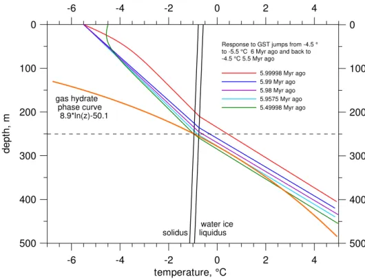
Figure 6 shows transient temperature-depth profiles corresponding to times 20, 10 000, 20 000 and 42 500 yr after the GST cooling from−4.5◦C to−5.5◦C 6 Myr ago, and to time 20 yr after the consequent warming back to−4.5◦C at 5.5 Myr ago,all that preceded by the whole GST history since 14 Myr ago. After the cooling at 6 Myr ago, the T-z profile started to move downward and touched the p-T phase curve of the GH
5
at the depth interval 290–300 m 42.5 ka after the GST drop (light blue profile in Fig. 6 for time 5.9575 Myr ago). At that moment, the IBP base was at the depth of 250 m. It means that there was an unfrozen depth section (250–290 m) separating IBP from hy-drate. With further subsurface cooling, the zone occupied by GH propagated not only downward, but also upward and after another 100 ka the upper GH boundary touched
10
the IBP base at the depth of 255 m. Upward spreading of the GH zone stopped at this moment, because all pore space in overlying IBP was occupied by frozen water. Nev-ertheless, this contact of IBP with GH, which stopped upward growth of the GH layer, does not stop downward migration of the IBP layer, because the model considers 60 % saturation of the pore space by hydrate. The rest of 40 % of the pore space (12 % of
15
the whole volume) was occupied by water, which could have frozen with subsequent cooling.
This scenario and consequences following from it for IBP and GH occurrence were taken into account by considering separately the porosity available for water ice and that for the hydrate. For the ice, it was 30 % above the line of the IBP–GH contact
20
at approximately 250 m and 12 % below it. Similarly, the porosity available for the GH above the line of contact at 250 m was considered to be 0 % and below it 18 % (60 % saturation in 30 % porosity rock). This opened the possibility to treat the latent heat released/consumed in the solidus-liquidus zones of IBP (0.334 MJ kg−1) and GH (0.430 MJ kg−1) independently and appropriately. The thermal conductivity in the zone
25
CPD
7, 2863–2891, 2011Modeling of stability of gas hydrates
J. Majorowicz et al.
Title Page
Abstract Introduction
Conclusions References
Tables Figures
◭ ◮
◭ ◮
Back Close
Full Screen / Esc
Printer-friendly Version Interactive Discussion
Discussion
P
a
per
|
Dis
cussion
P
a
per
|
Discussion
P
a
per
|
Discussio
n
P
a
per
|
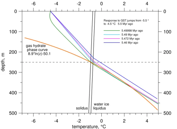
to form at time 5.9575 Myr ago reached its maximum thickness 125 m (between 255– 380 m) shortly after the next GST change from −5.5◦C to −4.5◦C, which occurred 5.5 Myr ago (Fig. 7). The same is true with the IBP, which penetrated into the GH only 4 m (255–259 m). As can be seen in Fig. 7, following that GST warming, the last GH disappeared in the depth range 310–340 m at time 5.472 Myr ago when it was
5
separated from the IBP base at the depth of 240 m by a 70 m thick melted zone. The GH formed again shortly after the next decrease of the GST from −5.0◦C to −5.5◦C 4.5 Myr ago. Since this moment, the GH survived all the following GST vari-ations. Its upper constraint at 250 m was always within the GH stability zone and its maximum extent to 990 m was reached during the most recent glacials.
10
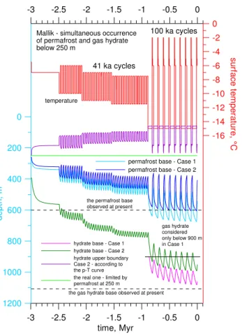
Depth variations of the IBP and GH upper and lower boundaries during the last 14 Myr are depicted in Fig. 8 and in detail for the last 3 Myr in Fig. 9. Also shown are variations of these parameters for the Case 1 Model, where the GH formation was restricted to the depth below 900 m only, and simultaneous occurrence of IBP and GH was not possible. The shallower position of both IBP and GH in this model
15
is caused by lower conductivity and consequently higher temperature gradient within the IBP in the zone of its simultaneous occurrence with GH below 250 m. It is also evident from Fig. 9 that depth variations of both the IBP and GH basis are slightly larger in Case 2 than Case 1 during the 41 ka and 100 ka cycles. The most probable reason for the larger variations of the IBP base is a smaller damping effect of the latent
20
heat release/consumption at the base due to a smaller amount of freezing/melting water/ice. Most of the pore water is bounded in the GH, which is stable in this depth range. The smaller damping effect at the IBP base also means that the subsurface
temperature changes propagate faster to the GH base and that these cause its larger depth variations compared to Model – Case 1.
25
CPD
7, 2863–2891, 2011Modeling of stability of gas hydrates
J. Majorowicz et al.
Title Page
Abstract Introduction
Conclusions References
Tables Figures
◭ ◮
◭ ◮
Back Close
Full Screen / Esc
Printer-friendly Version Interactive Discussion
Discussion
P
a
per
|
Dis
cussion
P
a
per
|
Discussion
P
a
per
|
Discussio
n
P
a
per
|
1. IBP thickness did not exceed 200 m before the time 6 Myr ago
2. GST temperatures higher than −5.5◦C prevailing before the time 6 Myr ago did not enable the GH to form
5
3. First GH formed in the depth range 290–300 m shortly after the time 6 Myr ago when the GST dropped from −4.5◦C to −5.5.◦C and started to spread both downward and upward. After another 100 ka, the upper GH boundary touched the IBP base propagating downward at the depth of 255 m
10
4. First GH disappeared after subsequent warming and formed definitively shortly after GST drop from −5◦C to −5.5◦C at time 4.5 Myr ago. Since this moment, the GH survived all the following GST variations. Its upper constraint at 250 m was always within the GH stability zone and its maximum extent to 990 m was reached during the most recent glacials.
15
5. Shortly after the definitive GH formation, the downward migrating IBP base and upward migrating upper GH boundary met at the depth of about 250 m. Since that moment, IBP below 250 m could have “used” only that part of the pore water, which was not bounded in hydrate.
20
The Case 2 model provides no mechanism enabling methane to escape to the earth surface from below the IBP lid formed 14 Myr ago. Its forecast of simultaneous occur-rence of IBP and GH below 250 m is, however, not generally observed Majorowicz et al. (2008).
25
CPD
7, 2863–2891, 2011Modeling of stability of gas hydrates
J. Majorowicz et al.
Title Page
Abstract Introduction
Conclusions References
Tables Figures
◭ ◮
◭ ◮
Back Close
Full Screen / Esc
Printer-friendly Version Interactive Discussion
Discussion
P
a
per
|
Dis
cussion
P
a
per
|
Discussion
P
a
per
|
Discussio
n
P
a
per
|
their position observed currently.
The indicated upper GH boundary above 250 m shown in Figs. 8–9 is a formal one. It was calculated according to the p-T phase curve. In reality, no GH was considered there because all pore space above 250 m is occupied by water ice and GH cannot form in a region already occupied by ice.
5
6 Discussion and conclusions
Historical surface temperature forcing as well as geological control have significant implications for both IBP and GHs model results that consider latent heat effects of
water/ice and GH formation and dissipation and 14Myr GST history.
Our model, in which we considered a stepwise approximation of the GST with a
10
length of the step 1 Myr between 14 and 6 Myr ago and 0.5 Myr between 6 and 2.5 Myr followed from 2.5 Myr ago by the 41 ka cycles and from 0.9 Myr by the 100 ka cycles, shows that the onset of GH formation always comes after IBP formation begins. IBP, provides a potentially impermeable seal for any upward gas migration and this is in-ferred to have existed long before the p-T conditions enabled formation of the first GH.
15
The models based on the two scenarios proposed, i.e;
Case 1: formation of GH from natural gas previously entrapped under a deep geological seal
Case 2: formation of GH from gas in all of the free pore space simultaneous with
20
IBP formation;
indicate two entirely different GH generation onset times for depending on model
as-sumptions. For Case 1: GHs could have formed at 0.9 km only some 0.9 Myr ago. For Case 2: the first GH formed in the depth range 290–300 m shortly after 6 Myr ago when
CPD
7, 2863–2891, 2011Modeling of stability of gas hydrates
J. Majorowicz et al.
Title Page
Abstract Introduction
Conclusions References
Tables Figures
◭ ◮
◭ ◮
Back Close
Full Screen / Esc
Printer-friendly Version Interactive Discussion
Discussion
P
a
per
|
Dis
cussion
P
a
per
|
Discussion
P
a
per
|
Discussio
n
P
a
per
|
the GST dropped from−4.5◦C to−5.5.◦C and started to spread both downward and upward.
In case 2, after all the pore water had frozen, methane contained in the freezing rock could be prevented from escaping to the surface by a IBP seal and this methane might have been pushed downward below the downward migrating IBP base. It is also
5
possible that this methane could have escaped to the sides of the IBP seal and then migrated upward.
Detailed models of recent ∼100 kyr cycles in the BMB area shows that GH layer thickness generally increases during colder intervals (i.e. glacial) and decreases during warmer intervals (i.e. interglacial). In the more recent glacial history of the∼100 ka
10
cycles these variations are ∼0.2 km for the IBP and about 0.1 km for the GH layer. Where the IBP layer is thick it is unlikely that sub-IBP GHs disappeared entirely during previous interglacial intervals, nor are they expected to disappear prior to the ‘natural’ end of the current interglacial. In regions of thick terrestrial IBP like the Mackenzie Delta, GH layers can act as a persistent sink for methane from deep thermogenic
15
sources and petroleum systems, and as a barrier to the migration of methane into the atmosphere.
The hypothesis that GHs destabilize rapidly in response to environmental change, late in glacial intervals, and that they serve, at other times, as a sink for, and barrier to the migration of, methane into the atmosphere applies mainly to marine non-IBP GHs
20
(Nisbet, 1990, 2002), which may be more easily destabilized than are the terrestrial sub-IBP GHs we modeled. Our study shows that sub-IBP GHs below thick IBP vary in thickness in response to surface temperature history changes, but that terrestrial thermal inertia conserves both IBP and sub-IBP GHs delaying and reducing methane release. Terrestrial thermal inertia also imposes a phase-delay between surface
tem-25
perature warming and the subsequent onset of GH dissociation, making it unlikely that terrestrial GHs below thick IBP could rapidly reinforce climate warming events, consistent with the hypothesis. The implications of latent heat effects and thermal
CPD
7, 2863–2891, 2011Modeling of stability of gas hydrates
J. Majorowicz et al.
Title Page
Abstract Introduction
Conclusions References
Tables Figures
◭ ◮
◭ ◮
Back Close
Full Screen / Esc
Printer-friendly Version Interactive Discussion
Discussion
P
a
per
|
Dis
cussion
P
a
per
|
Discussion
P
a
per
|
Discussio
n
P
a
per
|
consistent with the implications of recent observations of methane isotopic composi-tions from ice cores for the “clathrate gun” hypothesis of Sowers (2006).
This study shows that thermal modeling is essential for the understanding of the origin, growth and persistence of sub-IBP GH accumulations, as a function of temper-ature history. It can help to determine and distinguish the fetemper-atures of the GH geological
5
natural gas resource model, which have both climate and resource implications.
Acknowledgements. This work has been supported by Geological Survey of Canada and large part of it presented at the 6th International Gas Hydrate Conference in Vancouver, 2008.
References
Carslaw, H. S. and Jaeger, J. C.: Conduction of heat in solids, Oxford, Oxford University Press,
10
2nd ed., 1959.
Dallimore, S. R. and Collett, T. S.: Scientific results from the Mallik 2002 gas hydrate production research well program, Mackenzie Delta, Northwest Territories, Canada, Geol. Surv. Canada Bull., 585, 140 pp., CD and Charts, 2005.
Frakes, L. A., Francis, J. E., and Syktus, J. I.: Climate models of the Phanerozoic, Cambridge
15
Univ. Press, 1992.
Galushkin, Yu.: Numerical simulation of permafrost evolution as a part of sedimentary basin modeling: permafrost in the Pliocene-Holocene climate history of the Urengoy field in the West Siberian basin, Can. J. Earth Sci., 34, 935–948, 1997.
Henniges, J., Huenges, E., and Burkhard, H., In situ thermal conductivity of gas
hy-20
drate bearing sediments of the Mallik 5L-38 well, J. Geophys. Res., 110, B11206, doi:10.1029/2005JB003734, 2005.
Intergovernmental Panel on Climate Change,: Fourth Assessment Report Climate Change: Synthesis, Report 2007: http://www.ipcc.ch/pdf/assessment-report/ar4/syr/ar4 syr spm.pdf, 2007.
25
CPD
7, 2863–2891, 2011Modeling of stability of gas hydrates
J. Majorowicz et al.
Title Page
Abstract Introduction
Conclusions References
Tables Figures
◭ ◮
◭ ◮
Back Close
Full Screen / Esc
Printer-friendly Version Interactive Discussion
Discussion
P
a
per
|
Dis
cussion
P
a
per
|
Discussion
P
a
per
|
Discussio
n
P
a
per
|
Lawrence, K. T., Liu, Z., and Herbert, T. D.: Evolution of the Eastern Tropical Pacific Through Plio-Pleistocene Glaciation, Science, 312, 79–83, 2006.
Lorenson, T. D., Collett, T. S., and Whiticar, M. J.: Origin of gases in permafrost asso-ciated gas hydrate – Examples from Alaska and Canada. Hedeberg Conerence, Van-couver, http://www.searchanddiscovery.net/documents/abstracts/2004hedberg vancouver/
5
extended/lorenson/lorenson.htm, 2004.
Majorowicz, J. A. and Hannigan, P. K.: Stability zone of natural gas hydrates in a permafrost – bearing region of the Beaufort – Mackenzie basin – Study of a feasible energy source, Nat. Res. Res., 9, 3–25, 2000.
Majorowicz, J. A. and Smith, S. L.: Review of ground temperatures in the Mallik field area:
10
a constraint to the methane hydrate stability, in: JAPEX/JNOC/GSC Mallik, edited by: Dal-limore, S. R., Uchida, T., and Collett,T. S., 2L-38 Gas Hydrate Research Well, Mackenzie Delta, Northwest Territories, Canada, Geological Survey of Canada Bulletin, 544, 45–56, 1999.
Majorowicz, J. A. and Osadetz K. G.: Basic geological and geophysical controls bearing on gas
15
hydrate distribution and volume in Canada, AAPG Bulletin, 85/7, 1211–1230, 2001.
Majorowicz, J. A., Judge, A., and Jones, F. W.: Deep subpermafrost thermal regime in the Mackenzie Delta basin, northern Canada, – Analysis from petroleum bottom-hole tempera-ture data, Geophysics, 55, 362–371, 1990.
Majorowicz, J. A., Osadetz, K. G., and Safanda, J.: Modeling temperature profiles
consid-20
ering the latent heat of physical-chemical reactions in permafrost and gas hydrates – the Mackenzie Delta terrestrial case, in: Proceedings of the Ninth International Conference on Permafrost, edited by: Kane, D. L., and Hinkel, K. M., University of Alaska Fairbanks, Institute of Northern Engineering, 2, 1113–1118, 2008.
Muller, R. A. and MacDonald, G. J.: Ice ages and astronomical causes: data, spectral analysis,
25
and mechanisms, Berlin: Springer Praxis, 2000.
Nisbet, E. G.: The end of the ice age, Can. J. Earth Sci., 27, 148–157, 1990.
Nisbet, E. G.: Have sudden large releases of methane from geological reservoirs occurred since the Last Glacial Maximum, and could such releases occur again?, Phil. Trans. R. Soc. Lond. A, 360, 581–607, 2002.
30
Nixon, J. F.: Thermal simulation of subsea saline permafrost, Can. J. Earth Sci., 23, 2039– 2046, 1986.
eren-CPD
7, 2863–2891, 2011Modeling of stability of gas hydrates
J. Majorowicz et al.
Title Page
Abstract Introduction
Conclusions References
Tables Figures
◭ ◮
◭ ◮
Back Close
Full Screen / Esc
Printer-friendly Version Interactive Discussion
Discussion
P
a
per
|
Dis
cussion
P
a
per
|
Discussion
P
a
per
|
Discussio
n
P
a
per
|
tial equations, J. Soc. Ind. Appl. Math., 3, 28–41, 1955.
Polsson, K.: Climate Change – Carbon dioxide, http://www.islandnet.com/∼kpolsson/climate/ carbondioxide.htm, 2007.
Safanda, J., Szewczyk, J., and Majorowicz, J. A.: Geothermal evidence of very low glacial temperatures on the rim of the Fennoscandian ice sheet, Geophys. Res. Lett., 31, L07211,
5
doi:10.1029/2004GL019547, 2004.
Sloan, E. D.: Clathrate hydrates of natural gases, 2nd ed., New York, Marcel Dekker Inc., 1998. Sowers, T.: Late Quaternary atmospheric CH4 isotope record suggests marine clathrates are
stable, Science, 31, 838–840, 2006.
Taylor, A. E., Burgess, M., Judge, A., and Allen, V. S.: Canadian Geothermal Data Collection
10
¨
A Northern Wells 1981, Geothermal Series, Earth Physics Branch, E.M.R., Canada, 13, 153 pp., 1982.
Taylor, A. E.: Modelling the thermal regime of permafrost and gas hydrate deposits to determine the impact of climate warming. Mallik field area, in: JAPEX/JNOC/GSC Mallik 2L-38 Gas Hydrate Research Well, edited by: Dallimore, S. R., Uchida, T., and Collett, T.S., Mackenzie
15
Delta, Northwest Territories, Canada. Geological Survey of Canada Bulletin, 544, 391–401, 1999.
Taylor, A. E., Dallimore, S. R., Hyndman, R., and Wright, J. F.: Comparing the sensitivity of permafrost and marine gas hydrate to climate warming, in: Scientific Results from the Mallik 2002 Gas Hydrate Production Research Well Program, edited by: Dallimore, S. R. and
20
Collett,T. S., Mackenzie Delta, Northwest Territories, Canada, Geological Survey of Canada Bulletin , 585, CD paper 52, 2005.
Wikipedia.org: Geologic temperature record, http://en.wikipedia.org/wiki/Temperature record, 2008.
Wright, J. F., Nixon, F. M,, Dallimore, S. R., Henninges, J., and Cote M. M.: Thermal
con-25
CPD
7, 2863–2891, 2011Modeling of stability of gas hydrates
J. Majorowicz et al.
Title Page
Abstract Introduction
Conclusions References
Tables Figures
◭ ◮
◭ ◮
Back Close
Full Screen / Esc
Printer-friendly Version Interactive Discussion
Discussion
P
a
per
|
Dis
cussion
P
a
per
|
Discussion
P
a
per
|
Discussio
n
P
a
per
|
15
CPD
7, 2863–2891, 2011Modeling of stability of gas hydrates
J. Majorowicz et al.
Title Page
Abstract Introduction
Conclusions References
Tables Figures
◭ ◮
◭ ◮
Back Close
Full Screen / Esc
Printer-friendly Version Interactive Discussion
Discussion
P
a
per
|
Dis
cussion
P
a
per
|
Discussion
P
a
per
|
Discussio
n
P
a
per
|
-20 -15 -10 -5 0 5 10 15 20
temperature, °C 1500
1200 900 600 300 0
d
e
p
th
,
m
-20 -15 -10 -5 0 5 10 15 20
1500 1200 900 600 300 0
water ice solidus liquidus Steady-state profiles
60 mW/m2
frozen - thawed
conductivity 3.4 x 2.1 W/(m.K) water ice liquidus = -0.000715 *z(m)-0.064*CNaCl (g/L) 9 g NaCl,
hydrate phase curve 8.9*ln(z)-50.1
–
CPD
7, 2863–2891, 2011Modeling of stability of gas hydrates
J. Majorowicz et al.
Title Page
Abstract Introduction
Conclusions References
Tables Figures
◭ ◮
◭ ◮
Back Close
Full Screen / Esc
Printer-friendly Version Interactive Discussion
Discussion
P
a
per
|
Dis
cussion
P
a
per
|
Discussion
P
a
per
|
Discussio
n
P
a
per
|
-3 -2.5 -2 -1.5 -1 -0.5 0
time, Myr 0
200
400
600
800
1000
1200
d
e
p
th
,
m
-16 -14 -12 -10 -8 -6 -4 -2 0
s
u
rfa
c
e
te
m
p
e
ra
tu
re
, °
C
-3 -2.5 -2 -1.5 -1 -0.5 0
surface temperature permafrost base gas hydrate base below 900 m
41 ka cycles
100 ka cycles
the observed permafrost base
the observed gas hydrate base Mallik - permafrost and
gas hydrate simulation
gas hydrate considered only below 900 m
–
CPD
7, 2863–2891, 2011Modeling of stability of gas hydrates
J. Majorowicz et al.
Title Page
Abstract Introduction
Conclusions References
Tables Figures
◭ ◮
◭ ◮
Back Close
Full Screen / Esc
Printer-friendly Version Interactive Discussion
Discussion
P
a
per
|
Dis
cussion
P
a
per
|
Discussion
P
a
per
|
Discussio
n
P
a
per
|
-14 -12 -10 -8 -6 -4 -2 0
time, Myr 0
200
400
600
800
1000
1200
d
e
p
th
,
m
-16 -14 -12 -10 -8 -6 -4 -2 0
s
u
rfa
c
e
te
m
p
e
ra
tu
re
, °
C
-14 -12 -10 -8 -6 -4 -2 0
surface temperature permafrost base gas hydrate base Mallik - permafrost and gas hydrate simulation
100 ka cycles
41 ka cycles
gas hydrate considered only below 900 m the observed permafrost base
the observed gas hydrate base
–
Fig. 5.14 Myr history of surface temperature forcing, IBP and GH base depth variation – Case 1 model.
CPD
7, 2863–2891, 2011Modeling of stability of gas hydrates
J. Majorowicz et al.
Title Page
Abstract Introduction
Conclusions References
Tables Figures
◭ ◮
◭ ◮
Back Close
Full Screen / Esc
Printer-friendly Version Interactive Discussion
Discussion
P
a
per
|
Dis
cussion
P
a
per
|
Discussion
P
a
per
|
Discussio
n
P
a
per
|
-6 -4 -2 0 2 4
temperature, °C 500
400 300 200 100 0
d
e
p
th
,
m
500 400 300 200 100 0
-6 -4 -2 0 2 4
water ice solidus liquidus gas hydrate
phase curve 8.9*ln(z)-50.1
Response to GST jumps from -4.5 ° to -5.5 °C 6 Myr ago and back to -4.5 °C 5.5 Myr ago
5.99998 Myr ago 5.99 Myr ago 5.98 Myr ago 5.9575 Myr ago 5.49998 Myr ago
Fig. 6.Transient temperature-depth profiles as a response to the GST cooling from−4.5◦C to −5.5◦C 6 Myr ago (and to all previous GST history since 14 Myr ago) followed by warming back to−4.5◦C 5.5 Myr ago.
CPD
7, 2863–2891, 2011Modeling of stability of gas hydrates
J. Majorowicz et al.
Title Page
Abstract Introduction
Conclusions References
Tables Figures
◭ ◮
◭ ◮
Back Close
Full Screen / Esc
Printer-friendly Version Interactive Discussion
Discussion
P
a
per
|
Dis
cussion
P
a
per
|
Discussion
P
a
per
|
Discussio
n
P
a
per
|
-6 -4 -2 0 2 4
temperature, °C 500
400 300 200 100 0
d
e
p
th
,
m
500 400 300 200 100 0
-6 -4 -2 0 2 4
water ice solidus liquidus gas hydrate
phase curve 8.9*ln(z)-50.1
Response to GST jumps from -5.5 ° to -4.5 °C 5.5 Myr ago
5.49998 Myr ago 5.49 Myr ago 5.472 Myr ago 5.46 Myr ago
–
Fig. 7. Transient temperature-depth profiles as a response to the sudden GST warming from −5.5◦C to −4.5◦C 5.5 Myr ago and to all previous GST changes since 14 Myr ago. The pro-files correspond to times 20, 10 000, 28 000 and 40 000 yr after the warming. Curve for time 28 000 yr (5.472 Myr ago) shows the moment when the last GH disappears in the depth interval 310–340 m, separated from the IBP base at the depth of 240 m by a 70 m thick melted zone.
CPD
7, 2863–2891, 2011Modeling of stability of gas hydrates
J. Majorowicz et al.
Title Page
Abstract Introduction
Conclusions References
Tables Figures
◭ ◮
◭ ◮
Back Close
Full Screen / Esc
Printer-friendly Version Interactive Discussion
Discussion
P
a
per
|
Dis
cussion
P
a
per
|
Discussion
P
a
per
|
Discussio
n
P
a
per
|
-14 -12 -10 -8 -6 -4 -2 0
time, Myr 0
200
400
600
800
1000
1200
d
e
p
th
,
m
-16 -14 -12 -10 -8 -6 -4 -2 0
s
u
rfa
c
e
te
m
p
e
ra
tu
re
, °
C
-14 -12 -10 -8 -6 -4 -2 0
hydrate base - Case 1 hydrate base - Case 2 hydrate upper boundary - Case 2 according to the p-T curve the real one limited by permafrost at 250 m
Mallik - a simultaneous occurrence of permafrost and gas hydrate below 250 m
100 ka cycles
41 ka cycles
hydrate considered only below 900 m in Case 1 the permafrost base observed at present
the gas hydrate base observed at present
surface temperature
permafrost base - Case 1 permafrost base - case 2
Fig. 8. Depth variations of the IBP and GH upper and lower boundaries during the last 14 Myr for Case 2 compared with results of Case 1, where the GH formation was restricted to the depth below 900 m.
CPD
7, 2863–2891, 2011Modeling of stability of gas hydrates
J. Majorowicz et al.
Title Page
Abstract Introduction
Conclusions References
Tables Figures
◭ ◮
◭ ◮
Back Close
Full Screen / Esc
Printer-friendly Version Interactive Discussion
Discussion
P
a
per
|
Dis
cussion
P
a
per
|
Discussion
P
a
per
|
Discussio
n
P
a
per
|
-3 -2.5 -2 -1.5 -1 -0.5 0
time, Myr
0
200
400
600
800
1000
1200
d
e
p
th
,
m
-16 -14 -12 -10 -8 -6 -4 -2 0
s
u
rfa
c
e
te
m
p
e
ra
tu
re
, °
C
-3 -2.5 -2 -1.5 -1 -0.5 0
hydrate base - Case 1 hydrate base - Case 2 hydrate upper boundary Case 2 - according to the p-T curve the real one - limited by permafrost at 250 m
41 ka cycles
100 ka cycles
the permafrost base observed at present
the gas hydrate base observed at present Mallik - simultaneous occurrence of permafrost and gas hydrate below 250 m
gas hydrate considered only below 900 m in Case 1 permafrost base - Case 1 permafrost base - Case 2 temperature