PERFORMANCE EVALUATION OF
HYBRID FUZZY LOGIC CONTROLLER
FOR BRUSHLESS DC MOTOR DRIVE
C. SUBBA RAMI REDDY
Electrical & Electronics Engineering Department, KSRM College Of Engineering, Kadapa, Andhra Pradesh 516003, India
[email protected] http://<www.ksrmce.ac.in>
E-mail id : [email protected] Cell number : 09160993005, 09949827876
M. SURYA KALAVATHI
Electrical & Electronics Engineering Department, JNTUH College Of Engineering, Hyderabad, Andhra Pradesh 516003, India
[email protected] http://<www.jntu.ac.in>
Abstract :
This paper presents Hybrid fuzzy logic controller (HFLC) for the well developed and sophisticated simulation model of Brush less DC (BLDC) motor drive using MATLAB. The developed simulation model has been examined by the PID controller and HFLC. The performance of the controllers is evaluated more precisely from various simulation studies for variations in the load torque and speed of BLDC motor drive. A performance comparison of two controllers is also carried out by taking various performance measures such as settling time, steady state error, peak overshoot, the integral of the absolute value of the error (IAE) and the integral of the time-weighted squared error (ITSE). The results confirm that the developed simulation model is very convenient for the precise evaluation of performance and the HFLC shows improved performance over the PID controller in terms of disturbance rejection or parameter variation.
Keywords: HFLC; PID; BLDC; Speed Controller; Performance indices.
1. Introduction
In recent days, the Permanent magnet brushless DC motor (PMBLDCM) drives [1-2] are extensively used for many applications ranging from servo control to traction control. The invention of high energy rare earth permanent magnets have widely enhanced the applications of Brushless DC (BLDC) motors in order to meet the competitive world wide market demands of manufactured goods, devices, products and processors. The BLDC drives are suitable in clean, explosive environments such as robotics, machine tools, aeronautics, robotics, electric vehicles food and chemical industries [3-5] because of high efficiency, silent operation, compact form, reliability and low maintenance.
The usage of BLDC motors in high performance applications requires intelligent and robust control methods. The conventional control methods require the exact mathematical models describing the dynamics of the system. These methods are producing the overshoot during the transient period and the error is more for the variable loads and disturbances [6]. A fuzzy controller is a special fuzzy system that can be used as a controller component in a closed loop system. Fuzzy control provides a formal methodology for representing, manipulating and implementing a human heuristic knowledge about how to control a system [7]. The techniques of fuzzy logic control (FLC) have been used in many applications successfully [8-13].
precise performance during transient and steady state operation with the PID and HFLC and effectiveness of HFLC is verified by the results of various simulations.
2. Closed Loop Mathematical Model of BLDC Motor
The entire drive system consists of a BLDC motor fed by a three-phase PWM inverter, rotor position sensor, hysteresis current controller and speed controller. The inverter output voltage magnitude and frequency is in synchronous with the switching signals generated by the hysteresis controller [15]. The state of these switching signals at any instant is determined by the rotor position, speed error and winding currents. The controller synchronizes the winding currents with the rotor position. It also facilitates the variable speed operation of the drive and maintains the motor speed reference value even during load variations and supply fluctuations [16]. Fig.1 shows the block diagram of the closed loop drive of the BLDC motor.
Fig. 1. Block Diagram of Closed loop BLDC Motor Drive
2.1.BLDC Motor
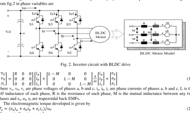
The modeling of BLDC motor is based on the assumptions in [17]. The circuit equations of three windings from fig.2 in phase variables are
Fig. 2. Inverter circuit with BLDC drive
0 0 0 0 0 0
0 0
0 0
0 0
(1)
where va, vb, vc are phase voltages of phases a, b and c, ia, ib, ic are phase currents of phases a, b and c, L is the
self inductance of each phase, R is the resistance of each phase, M is the mutual inductance between any two phases and ea, eb, ec are trapezoidal back EMFs.
The electromagnetic torque developed is given by
/ (2)
where ωr is the rotor speed.
The torque balance equation is expressed as
(3)
where TL is the load torque, J is inertia, P is the number of poles and B is damping.
2.2. Speed Controller
The output of the PID controller at any instant is the reference torque given by
(5) where kp is the proportional gain, ki is the integral gain, kd is the derivative gain and ωref is the reference speed.
2.3. Reference Current Generator
The magnitude of the reference current Irefis determined from the reference torque (Tref ) and the torque constant
(Kt).
I TK (6)
Depending upon the rotor position, the reference current generator generates the three phase reference currents (iaref, ibref , icref ) by taking the value of the reference current magnitude as Iref ,- Iref and 0.
2.4. Current Controller
The switching logic of the hysteresis current controller for all the phases is as follows.
If (ia < iaref – hb), switch 1 ON, switch 4 OFF If (ia > iaref + hb), switch 1 OFF, switch 4 ON
If (ib < ibref – hb), switch 3 ON, switch 6 OFF If (ib > ibref + hb), switch 3 OFF, switch 6
ON
If (ic < icref – hb), switch 5 ON, switch 2 OFF If (ic > icref + hb), switch 5 OFF, switch 2 ON
Where hb is the hysteresis band around the 3 phase reference currents.
3. Simulation of BLDC Drive with PID Controller
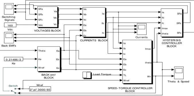
The fig. 3 shows the SIMULINK model of speed control of BLDC Motor with conventional PID controller. The control circuit determines the switching action to be performed based on rotor position feedback. The speed controller and the hysteresis current controller are used to maintain the speed and the current at the specified reference value. The hysteresis band is taken as 0.1 and DC voltage of 160V is applied to the inverter.
Fig. 3. SIMULINK block diagram with PID controller
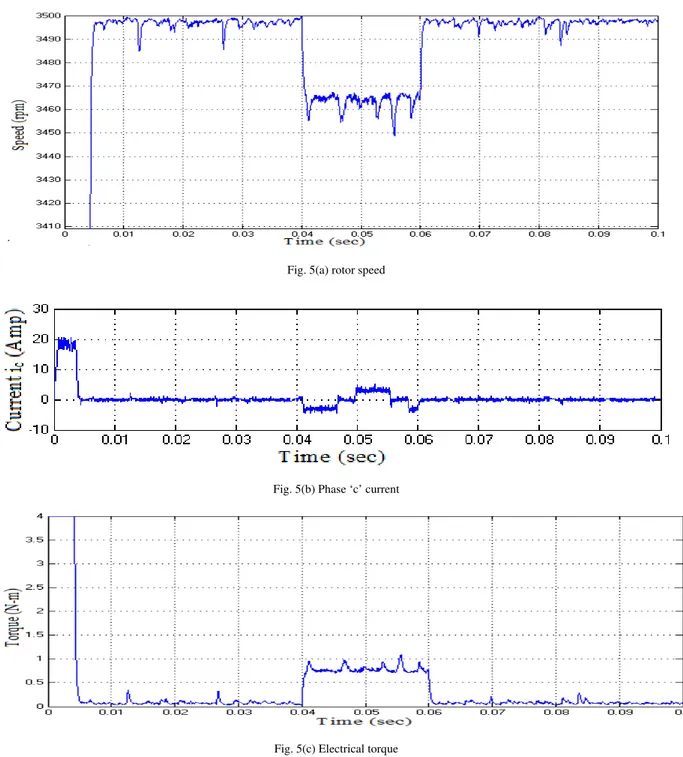
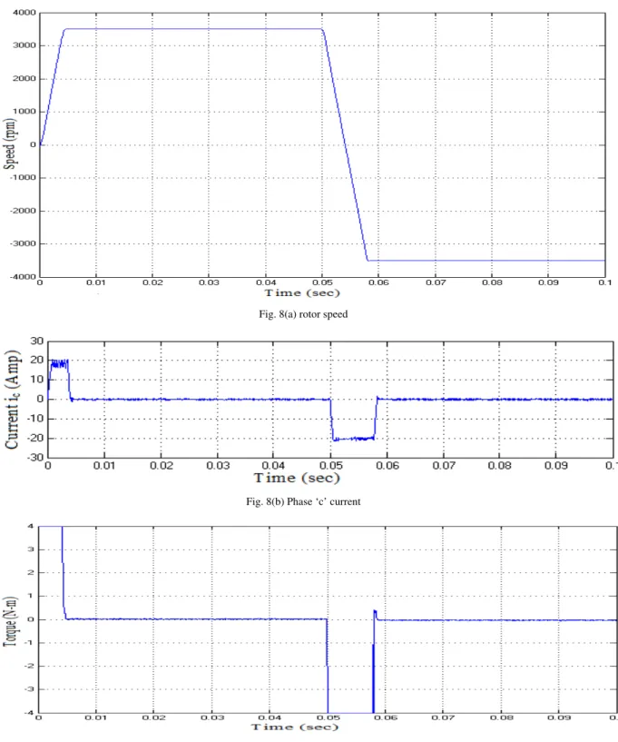
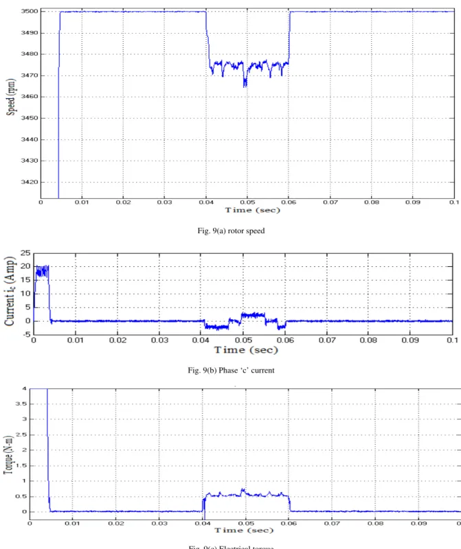
Fig. 4 shows the rotor speed, phase ‘c’ current and developed torque of BLDC motor with PID controller from standstill to a speed of 3500 rpm and when the motor is suddenly changed to other direction from steady state at t=0.05 sec. Fig. 5 shows the performance of the of BLDC motor with PID controller under load perturbation (applying load at t=0.04 sec and removal at t=0.06 sec.).
SPEED -TORQUE CONTROLLER BLOCK
Load Torque
Wref 2* pi* 3000 / 60 Vdc
160
VOLTAGES BLOCK
SFa SFb SFc Vdc Va Vb Vc
Theta & Speed Sw itching Signals Switch Ia Ib Ic Ea Eb Ec TL W ref Im ax
t het a
W r
Ke 0 .21486 / 2
HYSTERI SI S CONTROLLER BLOCK Ia Ib Ic Imax
t het a SFa
SFb
SFc
Currents CURRENTS BLOCK
Va Vb Vc Ea Eb Ec Ia Ib Ic Back EMFs
Fig.4(a) rotor speed
Fig.4(b) Phase ‘c’ current
Fig.4(c) Electrical torque
Fig. 5(a) rotor speed
Fig. 5(b) Phase ‘c’ current
Fig. 5(c) Electrical torque
Fig. 5. Transient and steady state performance of BLDC drive with PID controller during load perturbation
4. Simulation of BLDC Drive with Hybrid Fuzzy Logic Controller
4.1. Structure of the Hybrid Fuzzy Logic Controller
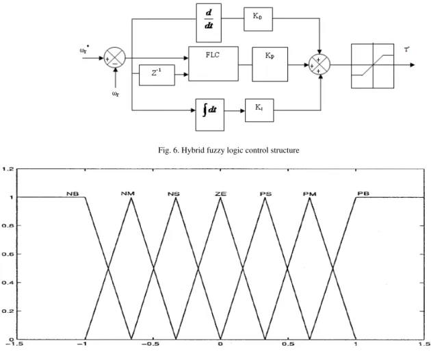
The basic control structure of the proposed HFLC is shown in fig. 6. The HFLC has the advantages of classical PID controller along with fuzzy control action. The dominating term in the HFLC is the proportional gain which is responsible to reduce overshoot and oscillations. All membership functions of the FLC inputs, e and Δe, and the output, Δu are defined on the common normalized domain [-1, 1] as shown in fig. 7. The characters NB, NM, NS, ZE, PS, PM and PB stand for negative big, negative medium, negative small, zero, positive small, positive medium and positive big respectively. Here triangular membership functions are chosen for NM, NS, ZE, PS, PM fuzzy sets and trapezoidal membership functions are chosen for fuzzy sets NB and PB. The rule base for computing the output Δu is in table 1. This is a very often used rule base designed with a two dimensional phase plane [21-22]. The control rules in table 1 are built based on the characteristics of the step response. The simulation of speed control of BLDC motor drive is done by using HFLC in place of PID controller.
Fig. 6. Hybrid fuzzy logic control structure
Fig. 7. Membership function of e, Δe and Δu
Table 1. Fuzzy rules for computation of Δu
e / Δe NB NM NS ZE PS PM PB
NB NB NB NB NM NS NS ZE
NM NB NM NM NM NS ZE PS
NS NB NM NS NS ZE PS PM
ZE NB NM NS ZE PS PM PB
PS NM NS ZE PS PS PM PB
PM NS ZE PS PM PM PM PB
PB ZE PS PS PM PB PB PB
4.2.Response of the BLDC Drive with HFLC
Fig. 8(a) rotor speed
Fig. 8(b) Phase ‘c’ current
Fig. 8(c) Electrical torque
Fig. 9(a) rotor speed
Fig. 9(b) Phase ‘c’ current
Fig. 9(c) Electrical torque
Fig. 9. Transient and steady state performance of BLDC drive with HFLC during load perturbation
5. Results and Discussion
reference following variation in load torque is found to be negligibly small along with a desirable reduction in settling time for the HFLC. The response is smooth and no oscillation in the case of HFLC. This is due to robust and accurate control structure of the HFLC. The results show significant improvement in the response of BLDC motor with the HFLC.
Table 2. Comparison of Performance Indices between PID Controller and HFLC
Refere
nce s
p
ee
d in rpm
Ty pe of C o nt ro ll er Time take
n to reach the
set sp eed (settlin g time)in sec.
Steady state error in rpm.
Dip i n s p ee d
when a loa
d of 0. 66 2 N -m i s appl ie d at t = 0 .04 sec in rpm. Peak Overs h oot Time take
n to reach the
set sp eed in th e rev erse d irectio n fr om t = 0. 05 sec . i n sec.
IAE ISE ITA
E
ITSE
3500
PID 0.0053 14 50 2.5 0.009 0.8998 222.1 0.003792 0.243
HFLC 0.0052 8 40 1.6 0.0087 0.8762 221.7 0.002813 0.239
3000
PID 0.0048 5 60 40 0.007 0.6805 151.8 0.001912 0.1481
HFLC 0.0047 3 37 30 0.007 0.6721 151.4 0.00184 0.1453
2500
PID 0.0044 1 40 38 0.0065 0.4672 86.62 0.001084 0.06998
HFLC 0.0041 0.8 35 31 0.006 0.4543 86.34 0.0007562 0.06934
2000
PID 0.004 3 35 65 0.0058 0.3208 48.59 0.0006825 0.03321
HFLC 0.00375 1 32 61 0.0056 0.3104 48.42 0.0004173 0.033
1500 PID 0.00357 2 35 40 0.0048 0.1973 22.38 0.0006087 0.01216
HFLC 0.0032 0.8 30 36 0.0047 0.1891 22.05 0.0003891 0.01192
1000 PID 0.0028 2 32 100 0.0037 0.1125 7.932 0.0008901 0.003416
HFLC 0.0026 0.6 28 90 0.0035 0.09634 7.74 0.0004729 0.003412
6. Conclusion
PID controller and HFLC have been employed for the speed control of BLDC motor. A performance comparison of PID controller and HFLC has been carried out by several simulations. The results have shown that HFLC is better than the PID controller for all the speeds. The conclusion is that HFLC is found to be superior, more robust, faster and flexible and is insensitive to the parameter variations as compared with conventional PI and PID controllers.
References
[1] Hendershort Jr, J.R.; Miller, T.J.E. (1994): Design of brushless permanent magnet motors, Oxford, U.K., Magna Physics/Clarendon. [2] Kenjo, T.; Nagamori, S. (1985): Permanent magnet and brushless dc motors, Oxford, U.K., Clarendon.
[3] Xia Changliang, et al. (2002a): Position sensorless control of brushless DC motor based on the disturbance observer, Transaction of china Electrotechnical society, vol. 17, no. 6, pp. 25-28.
[4] Xia Changliang, et al. (2002b): Based on RBF neural network position sensorless control for brushless DC motors, Transaction of china Electrotechnical society, vol. 17, no. 3, pp. 26-29.
[5] Xia Changliang, et al. (2005): Variable structure control of BLDCM based on extended state observer, ICMA 2005, Canada, pp. 568-571.
[6] Chen, G.(1996): Conventional and fuzzy PID controllers : An overview, Int. J. Intell. Control syst. ,Vol. 1, pp. 235-246.
[7] Tang, K.L.; Mulholland, R.J. (1987): Comparing fuzzy logic with classical controller designs, IEEE Trans. Syst., Man, Cybern., Vol. 17, pp. 1085-1087.
[8] Lee, C.C. (1990): Fuzzy logic in control systems : Fuzzy logic control – part 1 & part 2, IEEE Trans. Syst., Man, Cybern., Vol. 20, No. 2, pp. 404-435.
[9] Souza, G.C.D.; Bose, B.K. (1994): A fuzzy set theory based control of a phase-controlled converter DC machine drive, IEEE Trans. on IA, Vol. 30, No. 1, pp. 34-44.
[11] Indulkar, C.S.; Raj, B. (1995): Application of fuzzy controller to automatic generation control, Journal of electrical machines and power systems, Vol. 23, No. 2, pp. 209-220.
[12] Mattavelli, P., et al. (1997): General purpose fuzzy controller for DC- DC converters, IEEE Trans. on PE, Vol. 12, No. 1, pp. 79-86. [13] Cerruto, E., et al. (1997): Fuzzy adaptive vector control of induction motor drives, IEEE Trans. on PE, Vol. 12, No. 6, pp. 1026-1040. [14] Li, W. (1998): Design of a Hybrid fuzzy logic proportional plus conventional integral – derivative controller, IEEE Trans. on Fuzzy
systems, Vol.6, No. 4, pp. 449-463.
[15] Lee, B.K.; Ehsani, M. (2001): A simplified functional model for 3-phase voltage – source inverter using switching functional concept, IEEE Trans. on Industrial electronics, Vol. 48, No. 2, pp. 309-321.
[16] Lee, B.K.; Ehsani, M. (2003): Advanced simulation model for brushless DC motor drives, Electric power components and systems, Vol. 31, pp. 841-868.
[17] Safi, S.K.; Acarnley, P.P.; Jack, A.G. (1995): Analysis and simulation of the high – speed torque performance of brushless DC motor drives, Proc. of the IEE, Vol. 142, No. 3, pp. 191-200.
[18] Zadeh, L.A. (1965): Fuzzy sets in information and control, New York, Academic, Vol. 8, pp. 338-353.
[19] Sharma, V.K. (2002): Design and simulation of hybrid fuzzy logic controller for switched reluctance motor drive system, IE(I) Journal – EL, Vol. 8, pp. 100-105.
[20] Ali Akcayol, M., et al. (2003): An education tool for fuzzy logic controlled BLDC, IEEE Trans. on Education, Vol. 45, No. 3, pp. 33-42.
[21] Passino, Kelvin M.; Yurkovich, Stephen (1997): Fuzzy logic control, Addison – wesley. [22] Cirstea, M.N., et al. (2002): Neural and fuzzy logic control of drives and power systems, Newness.
Appendix A
Parameters of PID Controller and HFLC
Proportional gain kp = 0.2, Integral gain ki = 0.02 and Derivative gain kd = 0.0000012
Appendix B
BLDC Motor Specifications
Rating : 1 HP Rated speed : 3500 rpm
Rated voltage : 160 V dc Rated Torque : 0.662N-m
Number of poles : 4 Rated current : 5 A
Type of connection : star Resistance / phase : 0.75 Ω
Self & Mutual inductance : 3.05 x 10⁻³ H / Phase Moment of inertia : 0.82614x10⁻⁴ J