Synthetic Method, Improved Light Stability and
Application to Visualize Lymph Network Tracer
Liman Cong1, Motohiro Takeda1*, Yohei Hamanaka2, Kohsuke Gonda1, Mika Watanabe3, Masutaka
Kumasaka4, Yoshio Kobayashi5, Masaki Kobayashi4, Noriaki Ohuchi1,2
1Department of Nano-Medical Science, Graduate School of Medicine, Tohoku University, Sendai, Miyagi, Japan,2Department of Surgical Oncology, Graduate School of Medicine, Tohoku University, Sendai, Miyagi, Japan,3Department of Pathology, Tohoku University Hospital, Sendai, Miyagi, Japan,4Department of Electronics and Intelligent Systems, Tohoku Institute of Technology, Sendai, Miyagi, Japan,5Department of Biomolecular Functional Engineering, College of Engineering, Ibaraki University, Hitachi, Ibaraki, Japan
Abstract
Background:The sentinel lymph node biopsy (SLNB) was developed as a new modality in the surgical diagnosis of lymph node metastases. Dye and radioisotope are major tracers for the detection of sentinel lymph nodes (SLN). Dye tends to excessively infiltrate into the interstitium due to their small size (less than several nanometers), resulting in difficulties in maintaining clear surgical fields. Radioisotopes are available in limited number of hospitals. Fluorescent nanoparticles are good candidates for SLN tracer to solve these problems, as we can choose suitable particle size and fluorescence wavelength of near-infrared. However, the use of nanoparticles faces safety issues, and many attempts have been performed by giving insulating coats on nanoparticles. In addition, the preparation of the uniform insulating layer is important to decrease variations in the quality as an SLN tracer.
Methodology/Principal Findings:We herein succeeded in coating fluorescent polystyrene nanoparticles of 40 nm with uniform silica layer of 13 nm by the modified Sto¨ber method. The light stability of silica coated nanoparticles was 1.3-fold greater than noncoated nanoparticles. The popliteal lymph node could be visualized by the silica coated nanoparticles with injection in the rat feet.
Conclusions/Significance:The silica coated nanoparticles in lymph nodes could be observed by transmission electron microscope, suggesting that our silica coating method is useful as a SLN tracer with highly precise distribution of nanoparticles in histological evaluation. We also demonstrated for the first time that a prolonged enhancement of SLN is caused by the phagocytosis of fluorescent nanoparticles by both macrophages and dendritic cells.
Citation:Cong L, Takeda M, Hamanaka Y, Gonda K, Watanabe M, et al. (2010) Uniform Silica Coated Fluorescent Nanoparticles: Synthetic Method, Improved Light Stability and Application to Visualize Lymph Network Tracer. PLoS ONE 5(10): e13167. doi:10.1371/journal.pone.0013167
Editor:Maxim Antopolsky, University of Helsinki, Finland
ReceivedMay 12, 2010;AcceptedAugust 5, 2010;PublishedOctober 18, 2010
Copyright:ß2010 Cong et al. This is an open-access article distributed under the terms of the Creative Commons Attribution License, which permits unrestricted use, distribution, and reproduction in any medium, provided the original author and source are credited.
Funding:This work was supported by Grants-in-Aid for Scientific Research in Priority Areas from the Ministry of Education, Culture, Sports, Science and Technology of Japan and by Grants-in-aid for Research Projects, Promotion of Advanced Medical Technology from the Ministry of Health, Labor and Welfare of Japan. The authors also acknowledge the support of the Biomedical Research Core of Tohoku University Graduate School of Medicine, the 21st Century COE Program ‘‘Future Medical Engineering based on Bio-nanotechnology’’ and the Global COE Program ‘‘Global Nano-Biomedical Engineering Education and Research Network Center’’ committed by the Japan Society for the Promotion of Science, Japan-China Medical Association and Konica Minolta Medical and Graphic, Inc. The funders had no role in study design, data collection and analysis, decision to publish, or preparation of the manuscript.
Competing Interests:Motohiro Takeda and Kohsuke Gonda received research grants from Konica Minolta Medical and Graphic. Noriaki Ohuchi received research grants from Takeda Pharmaceutical Company Limited, and Konica Minolta Medical and Graphic. This does not alter the authors’ adherence to all the PLoS ONE policies on sharing data and materials. Liman Cong, Mika Watanabe, Yoshio Kobayashi, Masaki Kobayashi declare no competing interest.
* E-mail: [email protected]
Introduction
The metastatic status of the sentinel lymph nodes (SLN) is important for predicting the survival of malignancies. Since metastatic status of the SLN is highly predictive of involvement of the lymphatic system, the identification of SLN and biopsies are crucial in the staging of human cancers [1–3]. A tumor-negative SLN virtually excludes involvement of the regional lymphatics. Sentinel lymph node biopsy (SLNB) in breast cancer surgery has been developed to accurately assess axillary nodal status without removing most of the axillary contents, leading to avoid unnecessary axillary lymph node dissection in patients without axillary
To make up for these disadvantages, we used fluorescent nanoparticles to efficiently visualize SLN from outside the body and determined that the appropriate size and fluorescence wavelength in detection of SLN in animals from previous studies [7–8].
Polymer nanoparticles incorporating fluorescent dyes have been used for a wide variety of applications [9]. They have the potential for use as novel biomarkers to make major advances in medical diagnostics, targeting therapeutics, molecular biology and cell biology as ultrasensitive tracers for multicolor labeling [10–12]. Among such applications, the long-lasting marking of SLN or malignant lesions during the cancer surgery has a definite advantage for the surgical treatment [13–14]. However, many problems still remain for SLNB, such as safety, techniques to control size of nanoparticles, ideal track time and ideal modalities for the histological detection of sentinel node metastases. Preparation of insulating layer with physically stable material is an appropriate solution for some of these problems and silica is a good candidate as such materials.
In our previous study we performed silica coating for the 100 nm particles and the silica coated nanoparticles exhibited a more stable fluorescence to laser irradiation than the noncoated ones [10]. We also indicated that the appropriate size for SLNB is around 40 nm [8–9]. There have been no previous attempts to prepare silica coated fluorescent nanoparticles of 20 and 40 nm. Since silica coating is physically stable, it is expected to reduce the toxicity and enable tissue processing for microscopic observation without breakup of nanoparticles. In the present study, we performed silica coating for fluorescent 20 and 40 nm nanopar-ticles utilizing a seeded polymerization technique based on the Sto¨ber method and tried to clarify the suitability as SLN tracers by a rat model. We also performed histological examinations of the silica coated fluorescent nanoparticles for lymph nodes to clarify the modality of transportation of them by transmission electron microscopy (TEM).
Results
Formation of silica coating and concentration of TEOS
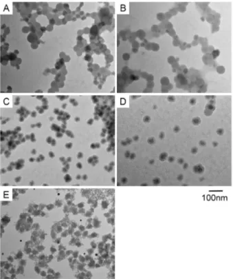
We performed the silica coating with various tetraethoxyortho-silicate (TEOS) concentrations ranging from 0.00038 to 0.2 M. Figure 1A and Figure 1B showed that low TEOS concentration of 0.00038 to 0.0015 M did not evoke formation of silica shell. Figure 1C shows that a TEOS concentration of 0.009 M evoked silica coating, but the nanoparticles aggregated. Figure 1D showed that a TEOS concentration of 0.02 M was optimal for the silica shell formation on 40 nm polystyrene nanoparticles, and Figure 1E showed that a high TEOS concentration (0.2 M) caused the formation of silica nanoclusters and silica coating could not be formed.
The distribution of diameter was shown in Figure 2. The silica shell thickness on 20 nm nanoparticles was 6.3+1.7 nm (Figure 2A) while the thickness of silica shell on 40 nm nanoparticles was 13.2+2.5 nm (Figure 2B). The silica shell thickness of 40 nm coated nanoparticles revealed a single peak while the silica coated 20 nm nanoparticles revealed two peaks in the histogram (Figure 2C and Figure 2D). We employed silica coated 40 nm nanoparticles for measurement of zeta potential and animal experiments on SLN detection.
The dispersion stability of the silica coated fluorescent nanoparticles was also measured by a zeta potential and submicron particle size analyzer (ELS-8000, Otsuka Electronics). The zeta potential of silica coated 40 nm nanoparticles was 22.4 mV at pH 7.2.
Figure 1. Electron microscopic images of fluorescent
nanopar-ticles with silica coating at various TEOS concentrations.(A)
Electron microscopic image of fluorescent nanoparticles and silica formation at 0.00038 M TEOS. (B) Fluorescent nanoparticles and silica formation at 0.0015 M TEOS. (C) Fluorescent nanoparticles and silica formation at 0.009 M TEOS. (D) Fluorescent nanoparticles and silica formation at 0.02 M TEOS. (E) Fluorescent nanoparticles and silica formation at 0.2 M TEOS.
doi:10.1371/journal.pone.0013167.g001
Figure 2. Electron microscopic images and distribution of silica
thickness on fluorescent nanoparticles of 20 and 40 nm.(A)
Electron microscopic image of 20 nm fluorescent nanoparticles with silica coating. (B) Electron microscopic image of 40 nm fluorescent nanoparticles with silica coating. (C) Distribution of silica coating thickness on 20 nm fluorescent nanoparticles. (D) Distribution of silica coating thickness on 40 nm fluorescent nanoparticles.
Fluorescence property of the fluorescent nanoparticles
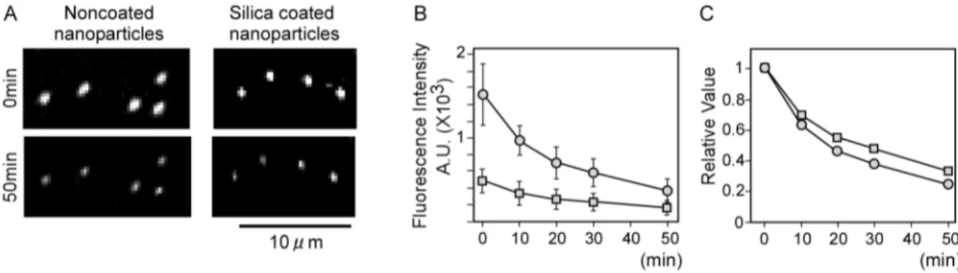
The comparison of the fluorescence property of the 40 nm nanoparticles before and after coating with 0.02 M TEOS is shown in Figure 3. A spectral analysis of the silica coated fluorescent nanoparticles exhibited no significant difference from the original nanoparticles (data not shown).
Florescence stability of noncoated and silica coated nanoparti-cles was estimated by continuous irradiation of laser light (Figure 3A). Although fluorescence intensity of noncoated nanoparticles was 3-fold higher than silica coated nanoparticles at 0 min (Figure 3B), the light stability of silica coated nanoparticles was 1.3-fold greater than noncoated nanoparticles (Figure 3C, 50 min).
Fluorescent imaging of the inguinal lymph nodes in rats
The silica coated fluorescent nanoparticles were injected subcutaneously in the feet of rats. The imaging set-up and fluorescent images by silica coated nanoparticles are shown in Figure 4. At 0 min and 180 min after injection, the lymphatic systems were not observed from outside the body for both
noncoated and coated nanoparticles (Figure 5A and 5B, and Figure 5E and 5F, respectively). As sentinel lymph nodes of the hind extremities are usually located in inguinal and popliteal regions, we assigned the sentinel node as an emerging fluorescence point after stripping the skin of the inguinal and popliteal regions. The fluorescent lymph nodes could be observed after stripping the skin in both cases with noncoated and coated nanoparticles (Figure 5C and Figure 5G, respectively). Macroscopic images at 180 min after skin stripping under light illumination are showed in Figure 5D and Figure 5H for the cases with noncoated and coated nanoparticles, respectively.
Histological analysis of the rat inguinal lymph nodes
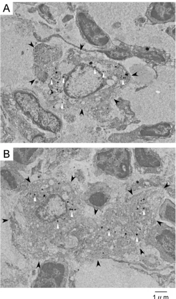
We observed inguinal lymph nodes by TEM (Figure 6A and Figure 6B). The inguinal lymph nodes were fixed by formalin and histological examinations were performed. The phagocytes of macrophages and dendritic cells were distinguished by their morphological features. Macrophages are polyhedral free reticu-lum cells with many pseudopods around the cell membrane. Dendritic cells are satellite-shaped tissue-specific reticulum cells with long radially extending processes. Figure 6A and Figure 6B are macrophages and dendritic cells with nanoparticles injection, respectively. The silica coated fluorescent nanoparticles were observed to be deposited in both the macrophages and dendritic cells by TEM (Figure 6A and Figure 6B) and fluorescence (images not shown).
Discussion
In this study, we used the modified Sto¨ber method to construct the silica coating on fluorescent nanoparticles in size of 20 and 40 nm. Under the low concentration of the TEOS (0.00038 to 0.009 M), the silica layer was not formed on the polystyrene particles. Under the optimal concentration of the TEOS at 0.02 M, the silica shells were formed and the particles did not aggregate. The thickness of the silica layer is homogenous and well controlled by this technique. More fine modification of TEOS around 0.02 M may lead to fine control of the shell thickness and diameter.
Nanoparticles for medical application should be stabilized by modification with hydrophilic or hydrophobic molecules in order to prevent aggregation in water or organic solvent, respectively [15]. In our study, the concentration of TEOS of 0.00038 to 0.009
Figure 3. Fluorescence images and intensities of silica coated and noncoated nanoparticles.(A) Fluorescence image of silica coated and
noncoated nanoparticles with continuous laser irradiation. (B) Changes in the fluorescence intensity of silica coated and noncoated nanoparticles with continuous laser irradiation. Open circles and squares show noncoated nanoparticles and silica coated nanoparticles, respectively (n = 10). Error bar, s.e.m. (C) Changes in the relative value of fluorescence intensity of silica coated and noncoated nanoparticles in (B). The mean value of fluorescence intensity at 0 min was defined as 1. Open circles and squares show noncoated nanoparticles and silica coated nanoparticles, respectively.
doi:10.1371/journal.pone.0013167.g003
Figure 4. Schematic of fluorescent imaging system. The
fluorescent imaging system was comprised of a laser unit, a resonant scanner, a cylindrical lens and a charge-coupled device camera and a computer.
M did not work for the silica coating of the fluorescent nanoparticles and resulted in the deposition of gel-like silica particulates around the fluorescent nanoparticles.
In clinical practice using the dye method to identify the SLN, the incision should be made within a few minutes since the dye moves instantaneously from the injection site to the lymphatic system. Moreover, if the lymph vessel is damaged by skin incision before dye moves to SLN, the lymph node will not be dyed. Furthermore, when a prolonged time is spent for detecting the SLN, many non-sentinel lymph nodes will also be dyed [16]. Previous studies have shown that large nanoparticles over 100 nm were not optimal for the detection of the SLN because they require so long period for movement to the SLN, and the ideal size was determined to be 40 nm among 20, 40, 100 and 200 nm [8]. The ideal SLN tracer arrives at a lymph node quickly and moves out from the lymph node slowly. Fluorescent nanoparticles are good candidates for such ideal tracers [17–21]. In this study, we observed the inguinal lymph nodes from 0 to 180 min after
injection. The silica coated fluorescent nanoparticles moved to these lymph nodesviathe lymphatic network under the skin.
The durability in enhancement of the silica coated 40 nm fluorescent nanoparticles was about 5 hr or more (data not shown). Use of near infrared avoids autofluorescence and improves the signal to noise ratio. The wavelength of near infrared is ideal for fluorescence measurement of the biological system in consideration with the autofluorescence spectrum [8].
Physical stability is an advantage of the silica coating and silica shell protected the inner polystyrene nanoparticles in the tissue processing for the microscopic and TEM observations. It is important to know the impact of the material on organisms andin vivo dynamics to realize clinical applications. Silica coated
fluorescent naonparticles could be tracked by both macroscopic fluorescence measurement and microscopic TEM observation. The translocation of a nanoparticle to the lymph vessels and the
Figure 5. Fluorescence images of sentinel nodes of rat lower
extremities by silica coated and noncoated nanoparticles.(A)
Fluorescence image at 0 min after injection of noncoated nanoparticles. (B) Fluorescence image at 180 min after injection of noncoated nanoparticles. (C) Fluorescence image at 180 min after injection of noncoated nanoparticles with skin stripping. (D) Image at 180 min under light illumination after injection of noncoated nanoparticles with skin stripping. (E) Fluorescence image at 0 min after injection of silica coated nanoparticles. (F) Fluorescence image at 180 min after injection of silica coated nanoparticles. (G) Fluorescence image at 180 min after injection of silica coated nanoparticles with skin stripping. (H) Image at 180 min under light illumination after injection of silica coated nanoparticles with skin stripping.
doi:10.1371/journal.pone.0013167.g005
Figure 6. Electron microscopic images of phagocytes in
inguinal lymph nodes.(A) A macrophage in inguinal lymph nodes
with silica coated fluorescent nanoparticles injection (Black arrow head; the outline of the macrophage, white arrow head; the silica coated fluorescent nanoparticles). (B) A dendritic cell in inguinal lymph nodes with silica coated fluorescent nanoparticles (Black arrow head; the outline of the dendritic cell, white arrow head; the silica coated fluorescent nanoparticles).
uptake to a lymph node depends upon the size of nanoparticles. Nanoparticles of small size are directly conveyed to a lymph node by the physical active transport of lymphatic flow. However, large-sized nanoparticles are passively conveyed by macrophages after phagocytosis.
The silica coated nanoparticles maintained enhancement for several hours. Prolonged enhancement is explained by phagocy-tosis of fluorescent nanoparticles by macrophages and dendritic cells in lymph nodes as shown in Figure 6. There has been no evidence identifying the cause of the prolonged enhancement of fluorescent nanoparticles since existing fluorescent polystyrene nanoparticles are easily broken in the process of sample preparation for TEM. We demonstrated, for the first time, the presence of fluorescent nanoparticles in macrophages and dendritic cells by TEM.
Although we used near infrared based on the optical traits of the organism to improve sensitivity, the limit for detection is less than 1 cm depth. Novel technologies are also expected for detecting fluorescence in deep sites of organs like the acousto-optic modulation imaging for realizing the fluorescence measurements in the SLNB [22].
Materials and Methods
Fluorescent nanoparticles
FluoSpheresH (Invitrogen) are commercially available fluores-cent polystyrene nanoparticles containing fluoresfluores-cent molecules within them. There are variations in the fluorescence wavelength (515 to 755 nm) and the particle size (20 to 1000 nm). The 20 nm and 40 nm fluorescent nanoparticles (8783, 2% solids and F-8789, 5% solids), with excitation/emission wavelengths of 660 nm/680 nm, were used for this experiment.
Reagents for the Silica Coating
The chemicals of polyvinylpyrrolidone (PVP), ethanol (95.5%), tetraethoxyorthosilicate (TEOS, 95%) and ammonia (NH4OH,
25% aqueous solution) were obtained from Wako Pure Chemical Industries. Ultrapure deionized water (resistivity higher than 18 MVcm) was used in the preparations for the silica coating.
Silica Coating Procedures
The silica coatings of fluorescent nanoparticles were performed in a hermetically sealed reactor equipped and the total volume of the reactor was 30 ml. We performed silica coating by dissolving PVP (0.3 g) in the water (5.571 ml) and then continuously agitated the solution with a magnetic stirrer until the complete dissolution of PVP. The PVP solution was vigorously stirred after the addition of fluorescent polystyrene nanoparticles (0.1 ml). Ethanol was subsequently added to the PVP/nanoparticles mixture and a pure silica precursor TEOS was added to the PVP/nanoparticles/ ethanol mixture. We used ethanol at volumes of 23.89, 23.88, 23.80, 23.75 and 22.48 ml for the concentrations of the TEOS of 0.00038, 0.0015, 0.009, 0.02 and 0.2 M in order to find the appropriate concentration for silica shell formation, respectively. Ammonia (0.42 ml) was added to the PVP/nanoparticles/ ethanol/TEOS mixture, followed by the incubation of the mixture at room temperature for 12 hr or more. The concentration of PVP, water and ammonia of the mixture were 10 g/l, 10.9 M and 0.4 M, respectively. And the volume of the mixture was 30 ml. The silica coated fluorescent nanoparticles were concentrated by a rotary evaporator (NE-1, Tokyo Rikakikai) and then were rinsed by a centrifuge (CP 70MX, Hitachi). The final volume of the silica coated fluorescent nanoparticle suspension was 10 ml.
Electron Microscopy
The silica coated fluorescent nanoparticles suspension was directly trickled onto the collodion membrane attachment mesh (Nisshin EM) and images were observed using a TEM (H-7600, Hitachi Science Systems). The TEM was operated at an 80–100 kV accelerating voltage.
Evaluation of fluorescence intensity
Fluorescence intensity of individual silica coated nanoparticles was estimated by a specially designed fluorescence measurement system. The system was composed of a fluorescent microscope (IX71, Olympus), an electron multiplying charge-coupled device camera (iXonEM+DU-897, Andor), a confocal unit with a Nipkow disc (CSU10, Yokogawa) and control computing system as noted in our previous study [23].
Preparation of the tissue sample
Tissue specimens were fixed and immobilized in 2% glutaral-dehyde buffered with 0.1 M sodium cacodylate buffer solution (pH 7.4). The tissue was washed with 3 changes of 0.1 M sodium cacodylate buffer (pH 7.4) and postfixed for 120 min in a solution of 1% OsO4 buffered with 0.1 M sodium cacodylate (pH 7.4), then washed in three changes of deionized water and dehydrated in 50% to 100% ethanol. Propyleneoxide was used as a transitional solvent. The tissue was infiltrated overnight in a 1:1 mixture of Epon-Araldite and propylene oxide. On the following day, the 1:1 mixture of Epon-Araldite and propylene oxide was removed and replaced with 100% Epon-Araldite. The tissue specimens were infiltrated with resin for 8 hr and polymerized for 48 hr at 60uC. The sentinel node tissue was embedded in a resin and cut into 60 nm thin sections by ultramicrotome (Ultracut S, Leica Microsystems). Thereafter, TEM observations were performed.
Instrumentation for fluorescence lymph node detection
A laser scanning fluorescence imaging system consisted of a laser unit, a resonant scanner (2K01, Optron) which resonant frequency is 200 Hz, a cylindrical lens and a charge-coupled device (CCD) camera (ORCA II-ER, Hamamatsu Photonics). A diode laser (wavelength 657 nm, 56ICS153/HS, Melles Griot) was used for excitation. The inguinal and femoral areas were continuously scanned over an area of 30650 mm. The
fluores-cence images were observed using a CCD camera with a band-pass filter (filter confer wavelength/680 nm, with full width at half maximum/30 mm) (Figure 4).
Animal Experiments
Male Donryu rats, 5–7 weeks old and 150–170 g in weight (Charles River Laboratories Japan) were used. They were anesthetized with pentobarbital sodium (20 mg/kg) by injection into the abdominal cavity. The hair on the lower half of the body was shaved to avoid autofluorescence. The rats were then fixed on a sample table in supine positions and the silica coated fluorescent nanoparticles suspensions of 50ml were injected in the foot pad of the hind leg. After observation through the skin for 180 min, the skin was stripped off and the SLN were removed. Histological observations by TEM were performed to detect silica coated nanoparticles in the lymph nodes.
Acknowledgments
We thank Mr. Mitsuji Kaji (Common Instrument Center, IDAC, Tohoku University) and Ms. Kiyomi Kisu (Graduate School of medicine, Tohoku University) for technical instruction for TEM. We also thank Prof. Mikio Konno and Associate Prof. Daisuke Nagao (Graduate School of Technology, Tohoku University) for the use of a zeta potential and submicron particle size analyzer.
Author Contributions
Conceived and designed the experiments: LC MT NO. Performed the experiments: LC MK YK. Analyzed the data: LC MT YH KG MW YK MK. Contributed reagents/materials/analysis tools: LC MT YH KG MW MK MK NO. Wrote the paper: LC MT.
References
1. Tuohy JL, Milgram J, Worley DR, Dernell WS (2009) A review of sentinel lymph node evaluation and the need for its incorporation into veterinary oncology. Vet Comp Oncol 7: 81–91.
2. Bonnema J, van de Velde CJ (2002) Sentinel lymph node biopsy in breast cancer. Ann Oncol 13: 1531–37.
3. Tangoku A, Seike J, Nakano K, Nagao T, Honda J, et al. (2006) Current status of sentinel lymph node navigation surgery in breast and gastrointestinal tract. J Med Invest 54: 1–18.
4. Sato K (2007) Current technical overviews of sentinel lymph node biopsy for breast cancer. Breast Cancer 14: 354–61.
5. Sato K, Shigenaga R, Ueda S, Shigekawa T, Krag DN (2007) Sentinel lymph node biopsy for breast cancer. J Surg Oncol 96: 322–29.
6. Sharma R, Wendt JA, Rasmussen JC, Adams KE, Marshall MV (2008) Sevick-Muraca EM. New horizons for imaging lymphatic function. Ann NY Acad Sci 1131: 13–36.
7. Shen J, Gilcrease MZ, Babiera GV, Ross MI, Meric-Bernstam F, et al. (2007) Feasibility and accuracy of sentinel lymph node biopsy after preoperative chemotherapy in breast cancer patients with documented axillary metastases. Cancer 109: 1255–63.
8. Nakajima M, Takeda M, Kobayashi M, Suzuki S, Ohuchi N (2005) Nano-sized fluorescent particles as new tracers for sentinel node detection: experimental model for decision of appropriate size and wavelength. Cancer Sci 96: 353–57. 9. Kobayashi Y, Misawa K, Kobayashi M, Takeda M, Konno M, et al. (2004) Silica-coating of fluorescence polystyrene microspheres by a seeded polymeri-zation technique and their photo-bleaching property. Colloid Surf A-Physiochem Eng Asp 242: 47–52.
10. Kobayashi Y, Misawa K, Kobayashi M, Takeda M, Konno M, et al. (2005) Silica-coating of fluorescent polystyrene microspheres by a modified Sto¨ber method and their stability against photo-bleaching. e-Polymers 052: 1–8. 11. Gu S, Anzai N, Nagao D, Kobayashi Y, Konno M (2005) Preparation of
fluorescent polymer particles by emulsion polymerization. e-Polymers 064: 1–5. 12. Kobayashi Y, Katakami H, Mine E, Nagao D, Konno M, et al. (2005) Silica coating of silver nanoparticles using a modified Sto¨ber method. J Colloid Interface Sci 283: 392–96.
13. Ballou B, Lagerholm BC, Ernst LA, Bruchez MP, Waggoner AS (2004) Noninvasive imaging of quantum dots in mice. Bioconjug Chem 15: 79–86. 14. Keshtgar MR, Chicken DW, Waddington WA, Raven W, Ell PJ (2005) A
training simulator for sentinel node biopsy in breast cancer: a new standard. Eur J Surg Oncol 31: 134–40.
15. Kim K, Kim HS, Park HK (2006) Facile method to prepare surface-enhanced-Raman-scattering-active Ag nanostructures on silica spheres. Langmuir 22: 8083–88.
16. Kim S, Lim YT, Soltesz EG, Bawendi MG (2004) Near-infrared fluorescent type II quantum dots for sentinel lymph node mapping. Nat Biotechnol 22: 93–97. 17. Yang M, Baranov E, Jiang P (2000) Whole-body optical imaging of green
fluorescent protein-expressing tumors and metastasis. Proc Natl Acad Sci USA 97: 1206–11.
18. Josephson L, Mahmood U, Wunderbaldinger P, Tang Y, Weissleder R (2003) Pan and sentinel lymph node visualization using a near-infrared fluorescent probe. Mol Imaging 2: 18–23.
19. Takeda M, Tada H, Higuchi H, Kobayashi Y, Kobayashi M, et al. (2008)In vivo single molecular imaging and sentinel node navigation by nano-technology for molecular targeting drug delivery system and tailor made medicine. Breast Cancer 15: 145–52.
20. Soltesz EG, Kim S, Laurence RG, DeGrand AM, Parungo CP, et al. (2005) Intraoperative sentinel lymph node mapping of the lung using near-infrared fluorescent quantum dots. Ann Thorac Surg 79: 269–77.
21. Soltesz EG, Kim S, Kim SW, Laurence RG, De Grand AM, et al. (2006) Sentinel lymph node mapping of the gastrointestinal tract by using invisible light. Ann Surg Oncol 13: 386–96.
22. Kobayashi M, Mizumoto T, Shibuya Y, Takeda M, Enomoto M (2006) Fluorescence tomography in turbid media based on acousto-optic modulation imaging. Appl Phys Lett 89: 181102.