American Journal of Applied Sciences 5 (2): 117-121, 2008 ISSN 1546-9239
© 2008 Science Publications
Corresponding Author: Nor Azlina Alias, Faculty of Civil & Environmental Engineering, University Malaysia Pahang, Locked Bag 12, 25000 Kuantan, Pahang, Malaysia. Tel : +609-5492282, Fax : +609-5492299
117
Impact of Takeoff Angle of Bucket Type Energy Dissipater on Scour Hole
1
Nor Azlina Alias,
2Thamer Ahmed Mohamed,
2Abdul Halim Ghazali,
2
Megat Johari Megat Mohd. Noor
1
Faculty of Civil & Environmental Engineering,
University Malaysia Pahang, Locked Bag 12, 25000 Kuantan, Pahang
2
Department of Civil Engineering, Faculty of Engineering, Universiti Putra Malaysia, 43400
UPM Serdang, Selangor, Malaysia
Abstract: Scour holes formed downstream of bucket type energy dissipater may affect the safety and stability of the structure. In this study, a physical model is employed to study the impact of takeoff angle of bucket type energy dissipater on the scour hole. The area of longitudinal profile of the scour hole is used to evaluate the seriousness of the scour at downstream of the bucket type energy dissipater. Experimental results showed that the takeoff angle of 45o is the optimum angle which gives minimum longitudinal area of the scour hole. Also, validation of selected equations for predicting maximum scour depth at downstream of the bucket type energy dissipater showed that the equation proposed by Schoklitsch gave minimum error (33%) [1].
Keywords: Flip bucket spillway, takeoff angle, physical model, scour hole, validation
INTRODUCTION
Scour occurs naturally due to erosive effects of flowing water including the morphological changes of rivers and also due to the construction of all types of structures in water ways. Excessive scouring can progressively undermine the foundations of hydraulic structures and cause failure. The scour downstream of hydraulic structures constitutes an important field of research due to its frequent occurrence in engineering applications. Several solutions to this problem were proposed in Europe and USA [1].
Hydraulic structures are built on waterways to control large volumes of water under high pressures. The released of the retained water is associated with tremendous amount of energy at the base or downstream of the structures. Kinetic energy carried out by turbulent jets can cause erosion in tailwater channels and failure of hydraulic structures, hence causing the local scour downstream on the hydraulic structures such as scour at vertical gates, flip bucket spillways, weirs and culverts. To prevent these problems, devices such as energy dissipaters are commonly used. The energy dissipater protects the foundation below the hydraulic structures by dissipating
the excess hydraulic energy in the turbulent jets and one of the energy dissipaters is known as flip bucket. Flip bucket is an integral part of an energy dissipation system and it is designed purposely to direct high velocity flow (jet) far away from the location of structure (Spillway). A flip bucket can be designed with various takeoff angles, and water jet formed is influenced by this angles. Energy is dissipated by friction through the bucket. The flip bucket is a more economical alternative to a stilling basin or other energy dissipaters.
The mechanism of scour is an extremely complex process due to the influence of various hydraulic, hydrological and geological factors. This why many previous experimental studies of scouring were limited to the consideration of governing variables involved. From the published literature, it is found that most of the proposed formulae for predicting maximum scour depth at downstream of hydraulic structures is empirical and the physical models were still the main tool used to study ultimately what had happen at the downstream hydraulic structures.
In this study, a physical model is employed to study the impact of flip bucket takeoff angle on the scour hole formed at downstream of flip bucket site.
Open Access
Author Manuscript
SCI-PUBLICATIONS
Author Manuscrip
SCOUR PREDICTION EQUATIONS
There are many formulae developed over the years to predict the maximum scour depth at downstream of hydraulic structure or spillway. Among these are Veronese, Mason and Arumugam and Yildiz and Uzucek Equations. The Veronese equation yields an estimate of erosion measured from the tail water surface to the bottom of the scour hole. This equation is given as
0.225 0.54
1.9
s o
Y
+
Y
=
H
q
(1)Where
Ys = Depth of scour Yo = Tailwater depth
H = Elevation difference between reservoir and tailwater
q = Unit discharge
Yildiz and Uzucek presents a modified version of the Veronese equation [2] as described below;
0.225 0.54
1.9
cos
s o
Y
+
Y
=
H
q
α
(2) WhereYs = Depth of scour Yo = Tailwater depth
H = Elevation difference between reservoir and tailwater
q = Unit discharge
α = angle of incidence from vertical of the jet
In contrast to Veronese equation, Mason and Arumugam equation includes a material factor, d [3]. This factor adequately represents the variety of properties found in foundation materials. This equation was based upon thorough research including a comprehensive collection of scale model studies and prototype case studies.
0.5 0.6 0.40
90
22.88
s o
Y
+
Y
=
H
q d
(3)Where
Ys = Depth of scour Yo = Tailwater depth
H = Elevation difference between reservoir and tailwater
q = Unit discharge
d90 = Median grain size of foundation material
Mason and Arumugam also proposed the following formula for weirs [3],
0.6 0.05 0.3 0.1
3.27
s o o m
Y
Y
q H
y g
−d
−+
=
(4)Where
Ys = Depth of scour Yo = Tailwater depth
H = Elevation difference between reservoir and tailwater
q = Unit discharge
g = acceleration of gravity
dm =Median grain size of foundation material
Martin comes out with the following equation for scour depth prediction at the downstream of ski jump spillway [4] through some prototype observations.
0.6 0.1
2
1.5
s o
Y
+
Y
=
q Z
(5)Where
Ys = Depth of scour Yo = Tailwater depth q = Unit discharge
Z2 = Difference in elevation between the free
surface of reservoir and the lip of flip bucket. Damle used model and prototype data for Indian dams with ski-jumps [5] and gave the following best-fit relation:
0.5
0.55(
)
s o
Y
+
Y
=
qH
(6)Where
Ys = Depth of scour Yo = Tailwater depth
H = Elevation difference between reservoir and tailwater
q = Unit discharge
Based on prototype data from dams in Taiwan, Chain [6] proposed the following formula:
.51 0.235
1.18
s o
Y
+
Y
=
q H
(7)Where
Ys = Depth of scour Yo = Tailwater depth
H = Elevation difference between reservoir and tailwater
q = Unit discharge
Schoklitsch[1] proposed the following equation to calculate the scour depth:
0.2 0.5
0.32 90
4.75
s d
H
q
d
S
h
D
=
+
=
(8) Whereds = Distance from the deepest point of the scour
Author Manuscrip
Am. J. Applied Sci., 5 (2): 117-121, 2008
hole to the downstream water surface
S = Depth of the scour hole
hd = Downstream water depth
H =Vertical distance between the energy grade line and the downstream water surface
q = Unit discharge
D90 = Particle size of which 90 percent of material
is finer
MATERIALS AND METHODS
The work presented herein focuses on the effect of takeoff angle of flip bucket type energy dissipater on scour hole formed at downstream with special comparison with straight drop spillway. Models of flip bucket spillway with various takeoff angles (10o, 20o, 30o, 45o and 60o) were tested to recommend the optimum angle which gives minimum downstream scour hole. Also, recorded maximum scour depths obtained from experiments are compared with the estimated scour depths using Equations (1),(2),(3),(4),(5),(6),(7) and (8). Experiments were conducted on glass sided flume with a layer of sand on its bed in order to simulate actual condition as much as possible. The flume is 500 cm in length, 7.6 cm in width and 25 cm in height. It is equipped with a shut-off valve, which was used to control the water flow rate. In this study, models of spillways were prepared from hard wood. The models were prepared following the standards for spillway design required by the United States Bereau of Reclamation (USBR). Five flip bucket models were prepared with 10o, 20o, 30o, 45o and 60o take off angles. Sand was put on the original bed of the flume to a distance of 1.5 m at the central part of the flume. Longitudinal slope of the flume is kept constant during the experiments and its value was found to be 0.0267. Experiments were done with different flow rates in order to test the effect of flow on scour depth. Each model is tested using three different flow rates which are categorized as low, medium and high flow rates. The measured values of the low, medium and high flow rates were 250 cm3/s, 750 cm3/s and 1500 cm3/s respectively. For each experiment, the scour depths were measured at different time. After the scour depth reached the equilibrium state, the profile of the scour hole was recorded. For low flow rate, the scour depths were measured at time intervals of 10 min while for medium and high flow rates the scour depths were measured at time intervals of 5 min. A total of 15 experiments were conducted.
RESULT AND DISCUSSION
The bucket type energy dissipater is cheaper than other conventional types of energy dissipaters and it is effective in dissipating water energy. Scouring hole at down stream is the main problem encountered with
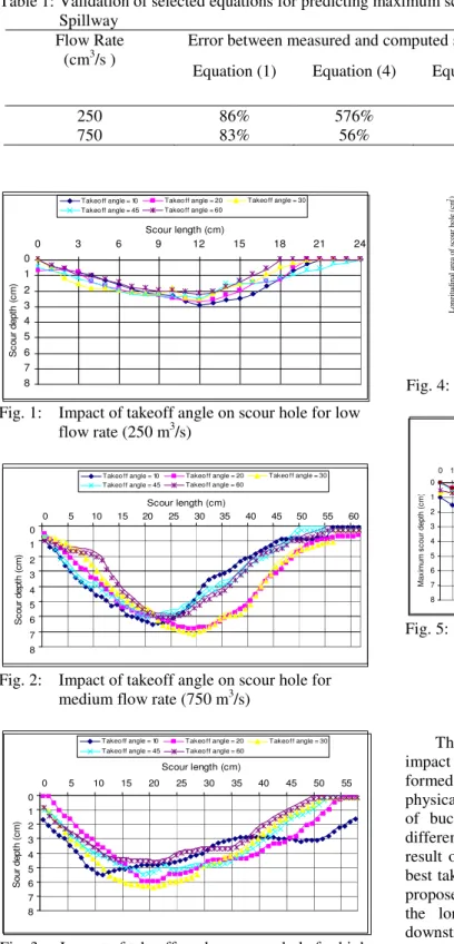
using flip bucket energy dissipater. So, for safety and stability of the structure, special attention must be given to monitor scour holes formed at downstream. The flip bucket type is dissipating energy by deflecting the flow upwards at a considerable angle to the horizontal and this angle called takeoff angle. Henderson recommended a takeoff angle of 45o to be used with flip buckets energy dissipaters but he did not give any basis for his recommendation [7]. So, takeoff angle may affect the scour hole and it is necessary to recommend the optimum angle that cause minimum scour hole at downstream of the flip bucket site. In this study, it is observed that the area of the longitudinal profile of scour hole changed with takeoff angle of the flip bucket and the flow arte. Figures 1,2, and 3 show the profiles of scour hole for different takeoff angles and flow rates. Figure 4 shows the effect of take off angle on the area of the scour hole for different flow rates. Small area of the profile of scour hole indicates that scouring at downstream of the flip bucket is not severe while big area indicates scouring at down stream is severe. For low flow, it is observed that the area is small for all tested angles. As a result, the impact of the takeoff angle on area of the profile of scour hole is not obvious. But for medium and high flow, the impact of the takeoff angle on the area of longitudinal profile of scour hole is obvious. It is also observed that there is a marginal difference ( 6%) between the areas of the longitudinal profile of scour holes which resulted from takeoff angles of 45o and 60o. This is attributed to the fact that high takeoff angle will have a retarding action to reduce the velocity and momentum. So, the energy of water jet for takeoff angles of 45o and 60o is less than the energy of jets for other smaller takeoff angles. However, the difference between the energy of water jets (for take off angles of 45o and 60o ) is small.
It can be seen from Figure 5 that all flip bucket models (with various takeoff angles) produced smaller longitudinal area for scour hole than the straight drop spillway model. This indicates that flip buckets spillway is more effective in dissipating water energy than the straight drop spillway.
The collected data from the experiments is used to validate selected equations for predicting scour depth at downstream of bucket type spillway. Equations (1),(4), (6),(7) and (8) have been tested as shown in Table1 and validation process revealed that the minimum percentage errors in predicting scour depth at downstream of the bucket type spillway are obtained from the application of Equation (8).
SCI-PUBLICATIONS
Author Manuscrip
Table 1: Validation of selected equations for predicting maximum scour depth downstream of bucket type Spillway
Error between measured and computed scour depths Flow Rate
(cm3/s )
Equation (1) Equation (4) Equation (6) Equation (7) Equation (8)
250 86% 576% 80% 68% 38%
750 83% 56% 77% 56% 28%
0 1 2 3 4 5 6 7 8
0 3 6 9 12 15 18 21 24
Scour length (cm)
S c o u r d e p th ( c m )
Takeo ff angle = 10 Takeo ff angle = 20 Takeo ff angle = 30 Takeo ff angle = 45 Takeo ff angle = 60
Fig. 1: Impact of takeoff angle on scour hole for low flowrate (250 m3/s)
0 1 2 3 4 5 6 7 8
0 5 10 15 20 25 30 35 40 45 50 55 60 Scour length (cm)
S c o u r d e p th ( c m )
Takeo ff angle = 10 Takeo ff angle = 20 Takeo ff angle = 30 Takeo ff angle = 45 Takeo ff angle = 60
Fig. 2: Impact of takeoff angle on scour hole for medium flow rate (750 m3/s)
0 1 2 3 4 5 6 7 8
0 5 10 15 20 25 30 35 40 45 50 55 Scour length (cm)
S o u r d e p th ( c m )
Takeo ff angle = 10 Takeo ff angle = 20 Takeo ff angle = 30 Takeo ff angle = 45 Takeo ff angle = 60
Fig. 3 : Impact of takeoff angle on scour hole for high flow rate (1500m3/s)
0 100 200 300 400
10 30 50 70
Takeoff angle (degree)
L o n g it u d in al a re a o f sc o u r h o le ( cm
2) Q=250 cm3/s
Q=750 cm3/s Q=1500 cm3/s
Fig. 4: Variation of the area of longitudinal profile of scour hole 0 1 2 3 4 5 6 7 8
0 1 2 3 4 5 6 7 8 9 10 11 12 13 14 15 16 17 18 19 20 21 22 23 24 Distance f rom structure (cm)
M a x im u m s c o u r d e p th ( c m )
Straight dro p Takeo ff angle = 10 Takeo ff angle = 20 Takeo ff angle = 30 Takeo ff angle = 45 Takeo ff angle = 60
Fig. 5: Comparison between flip bucket spillway models and straight drop spillway model at 250 cm3/s flow rate
SUMMARY AND CONCLUSIONS
The present study has been set out to test the impact of takeoff angle and flow rate on scour hole formed at downstream of bucket type spillway. A physical model simulating the scouring at downstream of bucket type spillway is employed. Among five different takeoff angles for the bucket type spillway, result obtained from the experiments revealed that the best takeoff angle is 45o. This is in agreement with the proposed takeoff given by Henderson [7]. The area of the longitudinal profile of scour hole formed at downstream of the bucket type spillway was found minimum when the takeoff angle is 45o. Validation for selected equations proposed to predict the maximum
Author Manuscrip
Am. J. Applied Sci., 5 (2): 117-121, 2008
scour depth at the scour hole is conducted and the average minimum error was found to be 33% which is obtained form applying Equation (8) [1] while the maximum error was found to be 84.5% and obtained form applying Equation (1). So, it is found that Equation (8) by Schoklitch [1] gave a minimum error.
REFERENCES
1. Breusers, H. N. C., and Raudkivi, A. J., 1991., Scouring Hydraulic Structures Design Manual Series, No 2, Taylor & Francis, pp. 116-121 2. Yildiz, D., and Uzucek, E., 1994. Prediction of
Scour Depth from Free Falling Flip Bucket Jets., Intl. Water Power and Dam Construction.
3. Mason, P.J. and Arumugam, K., 1985, Free Jet Scour Below Dams and Flip Buckets, Journal of Hydraulic Engineering, ASCE; 111(2) pp. 220-235 4. Martin, R.B.F., 1975. Scouring of Rocky River
Beds by Free Jet Spillway., Water Power and Dams Construction, pp. 152-153
5. Damle, P.M. et al., 1966. Evaluation of Scour Below Ski Jump Bucket of Spillways. Proc. Golden Jubilee Symp., Poona; pp. 154-164 6. Chain, M.W., 1973., Scour at Downstream End
Dam in Taiwan., Proc. IAHR Symp. On River Mechanics, Bangkok, paper A13
7. Henderson, F.M., 1966. Open Channel Flow.Macmillan Company, New York.