ISSN:2249-7838 IJECCT | www.ijecct.org
532
Analysis of Burst Assembly Modeling for Optical
Burst Switched Network
Bhumika Patel
Department of Computer Science Shrinathji Institute of Technical Education
Rajasthan Technical University Nathdwara, India
Ajay Dhabariya
Assistant Professor, Dept. of Computer Science Shrinathji Institute of Technical Education
Rajasthan Technical University Nathdwara, India
Abstract—In this paper, we have study the current state of
the technology, the Optical burst Switched (OBS) network is the most practical in all-optical architecture. Here we define how Burst Assembly will carried out and also here in the network architecture each node is consist of Core router and Edge router. Moreover we define challenges faced at practical implementation of OBS and proposed its unique solution at the node as Delay model.
Keywords- OBS Network; Burst Assembly; Core Router; Edge Router; Engset model; Delay Model.
I. INTRODUCTION
This OBS networks allow for a greater degree of statistical multiplexing and are better suited for handling bursty traffic than optical circuit-switched networks [1]. The user data is transmitted in variable size data packets, called bursts, which travel as an optical signal along the entire route. The control information for each burst is transmitted prior to its corresponding burst and it is electrically processed at each hop along the route. The dynamic nature of OBS allows for network adaptability and scalability, which makes it very suitable for the transmission of Internet traffic. In addition, this paper identifies a unique proposed technique to resolve all current challenges by carefully handling the burst assembly unit.
II. OPTICAL BURST SWITCHING
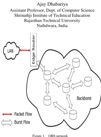
First, confirm that An OBS networks consist of core nodes and end devices interconnected by WDM fibers as shown in Figure 1. An OBS core node consists of an optical cross connect (OXC), an electronic switch control unit, and routing and signaling processors [3]. An OXC is a non- blocking switch that can switch an optical signal from an input port to output port without converting the signal to electronics. The OBS end- devices are equipped with an OBS interface and could be electronic IP routers, ATM switches, switches etc. Each OBS end-device is connected to an ingress OBS core node.
Figure 1. OBS network
The end-device collects traffic from various electronic networks (such as ATM, IP, frame relay, etc). It sorts the traffic per destination OBS end-device address and assembles it into larger variable-size units, called burst. For each burst, the end-device also constructs a control packet, which contains information about the burst, such as the burst length, burst destination address etc.
III. BURST ASSEMBLY UNIT
ISSN:2249-7838 IJECCT | www.ijecct.org
533
Figure 2. General Idea of offset timeThe Edge Router showing in figure 3, perform the function of pre-sorting packets, buffering packets, assembling packets into burst, and disassembling packets into its constituent packets. Different burst assembly policies, such as a threshold policy or a timer mechanism [1] can be used to aggregate bursty data packets into optical burst and to send the bursts into the network. Edge router consists of routing module, a burst assembler, and a scheduler [1]. Burst assembler separates traffic according to class and scheduler creates burst based on the any of assembling techniques.
Figure 3. Architecture of edge router
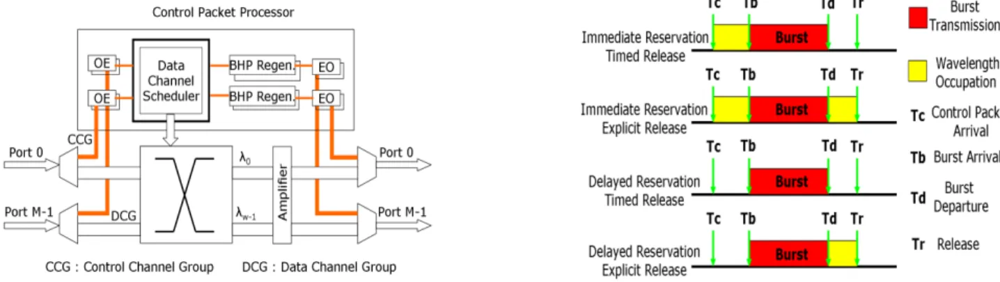
Architecture of core router shown in figure 4. In core node control packet is first converted in electronic form, control packet then reserve resource for burst through data channel scheduler. This electronic control packet is again converted back into optical form and then multiplexed together with the data.
Figure 4. Architecture of core router
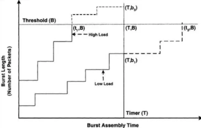
IV. RESERVATION AND RELEASE OF THE RESOURCES Upon receipt of a control packet, an OBS node processes the included burst information. It also allocates resources in its switch fabric that will permit the incoming burst to be switched out on an output port toward the destination. In [4] classify the resource reservation and release schemes in OBS based on the amount of time a burst occupies a path inside the switching fabric of an OBS node. There are two OBS resource reservation schemes, namely, immediate reservation and delayed reservation. In the immediate reservation scheme, the control unit configures the switch fabric to switch the burst to the correct output port immediately after it has processed the control packet. In the delayed reservation scheme, the control unit uses the offset parameter to calculate the time arrival
T
b of the burst at the node, and it configures the switch fabric atT
b.There are also two different resources release schemes, namely, timed released and explicit release. In the timed – release scheme the control unit uses the burst length information to calculate when the burst will completely go through the switch fabric. When this time occurs, it instructs the switch fabric to release the allocated resources. This requires knowledge of the burst duration. An alternative scheme is the explicit release scheme, where the transmitting end-device sends a release message to inform the OBS nodes along path of the bursts that it has finished its transmission. The control unit instructs the switch fabric to release the connection when it receives this message. Combining the two reservation schemes with the two release schemes results in the following four possibilities: immediate reservation and explicit release, immediate reservation and timed release, delayed reservation and explicit release and delayed reservation and timed release, see Figure 5. Each of these schemes has advantages and disadvantages. For example, when timed release is implemented the OBS core node knows the exact length of the burst. Thus, it can release the resources immediately upon burst departure. This result in shorter occupation periods and thus higher network throughput than in the explicit release. The difficulty, however, is that the timed-release schemes require complicated scheduling and their performance greatly depends on whether the offset estimates are correct. On the contrary, the immediate reservation/ explicit release scheme requires no scheduling. It is easier to implement, but it occupies the switching fabrics for longer periods than the actual burst transmission. Therefore, it may result in a high burst loss.
ISSN:2249-7838 IJECCT | www.ijecct.org
534
In the OBS literature, the three most popular OBS variantsare Just-In-Time (JIT) [11], Just-Enough-Time (JET) [10] and Horizon [12]. They mainly differ based on their wavelength reservation schemes. The JIT protocol utilizes the immediate reservation scheme while the JET protocol uses the delayed reservation scheme. The Horizon reservation scheme can be classified as somewhere between immediate and delayed. In Horizon, upon receipt of the control packet, the control unit scheduler assigns the wavelength whose deadline (horizon) to become free is closest to the time before the burst arrives.
Here the challenge how to reduce the high burst loss with JET and complicated scheduling with JIT as these scheme follows immediate reservation and delayed reservation respectively. In [12] they suggest horizon, which not only improve over the burst loss and heavy scheduling tasks but provide optimum solution in term of end to end delay and throughput. However, in [12] they suggest few more versions of horizon to ponder upon.
V. PROPOSED OPTIMIZED SOLUTION
Up till now, we have discussed different challenges at different levels like the implementation of different class of services through priority queue based techniques, the burst lost problem can be solved by fiber delay line and deflection routing, the effective routing problem can be addressed by the explicit routing and the wavelength assignment issue can be resolved by parallel wavelength reservation scheme in the OBS network.
Instead of resolving all the above challenges in the core OBS network frame work, I have proposed an optimized way of dealing with all the issues at the burst assembly unit (Ingress Node) itself. Just to illustrate the proposed solution, I have taken a delay problem in OBS network. Instead of using delay expensive and bulky FDLs in network; we can resolve the issue by controlling length of burst at the burst assembly unit at edge node [9].
TABLEI:DELAY OF DIFFERENT FIBER CAPACITY AND BURST LENGTH FOR
PROPOSED SOLUTION
Burst Length
Fiber Capacity with Delay (ms)
1.25 Gbps 2.25 Gbps 4 Gbps 5 Gbps
30 Kb 2.24 2.15 2.1 2.06
50 Kb 2.4 2.2 2.15 2.1
100 Kb 2.8 2.4 2.25 2.2
200 Kb 3.6 2.6 2.5 2.4
Above table I, shows different delays with different fiber capacity according to burst length. At the network level we knows the capacity of fiber lines and required delay to resolve the burst lost probability (contentions), we can directly set the burst length to fulfill the above constraints by suitably means of controlling the burst length at burst assembly unit at the edge node of OBS network.
For example if we have 4 Gbps of fiber lines in network, and the required delay for minimum burst blocking probability is 2.25ms, then burst length comes out to be 100kb which can be directly handle by the burst assembly unit at the ingress node, rather than inside the network by using FDL in the OBS network.
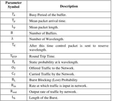
In figure 6 observe that for the lower traffic, the burst with fixed length takes longer time to assemble. Contrary to this assembly time for the same burst length at higher traffic is comparatively less. The selection of appropriate consideration of burst assembly time & burst length is necessary so as to keep the blocking probability low.
Figure 6. Effect of traffic on burst length & burst assembly time.
VI. MATHEMATICAL MODEL
A. Engset Model
For the calculation of burst blocking probability at edge router, we have considered Engset model [5]. For the edge
router served by λ wavelength channel and B buffer as shown
in figure 7, the capacity of buffers are such that it will prevent over flow. Packet in the buffer is aggregated and make burst.
When a packet arrives at an empty buffer, after a time
interval, a control packet is sent to reserve one of the λ
channels for the burst currently being assembled. The time interval is a design parameter controlling the burst assembly delay. If a channel is reserved, an acknowledgement is received by the edge router after a further round-trip propagation delay and the burst is sent via the channel. Only when the buffer is empty, a trailer packet is sent to release the reserved channel. Then, another packet may arrive and the assembly of a new burst will commence.
ISSN:2249-7838 IJECCT | www.ijecct.org
535
TABLEII:PARAMETER FOR THE ENGSET MODELParameter
Symbol Description
Busy Period of the buffer.
Mean packet arrival time.
Mean packet length.
B Number of Buffers. λ Number of Wavelength.
After this time control packet is sent to reserve wavelength.
Round Trip Time.
Static probability at k wavelength.
Offered Traffic to the Network.
Carried Traffic by the Network.
Burst Blocking (Lost) Probability
Rate at which traffic is input in network.
Output rate of traffic by network. Length of the Burst.
According to state of buffer we have main idle and busy periods denoted by and respectively. The busy period of the buffer, can be calculated using formula derived in [5], [6] and given here as equation (1). Since as in equation (2).
Now from the on-off model [7],[8] and is mean on and off times respectively. From
these times we can calculate variable α as in equation (3).
can be used to derive stationary probability for the number of busy channels as in equation (4).
With the help of stationary probability, the offered traffic load and carried traffic load can be calculated as shown in equation (5) and (6) respectively, based on this Burst Blocking (Lost) Probability will carried out as in equation (7).
Delay Model:
In a packet transport network larger burst having multiple packets may have longer delays due to queuing at node. The burst assembling delay [9] for the lower traffic can be expressed in equation (8). And with the higher traffic load the burst assembling delay can be expressed as in equation (9).
TABLE III :PARAMETERS FOR THE DELAY MODEL
Parameter Symbol Description
N Number of nodes
Fiber capacity
Round trip time
Length of the burst
Traffic load
X Constant
Y Constant Inversely proportional to fiber capacity ( ) & number of wavelength
ISSN:2249-7838 IJECCT | www.ijecct.org
536
Where the mean packet size in bits, λ is is the meanflow in packets/sec. So with the help of the delay at lower and higher traffic load shown in (8) and (9) respectively, the average delay T can be calculated as in equation (10).
ACKNOWLEDGMENT
I would like to express my gratitude and sincere thanks to Asst .prof. Mr. Ajay Dhabariya Dept. of Computer Science for allowing me to undertake this thesis work and for his guidelines during the review process. I am deeply indebted to my thesis supervisor Mr. Ajay Dhabariya for his constant guidance and motivation. He has devoted significant amount of his valuable time to plan and discuss the thesis work. Without his experience and insights, it would have been very difficult to do quality work. I wish to thank my friends of my class for their delightful company which kept me in good humor throughout the year. Last, but not the least, no words are enough to acknowledge constant support and sacrifices of my Husband and family members because of whom I am able to complete the degree program successfully.
REFERENCES
[1] Jason P. Jue, Vinod M. Vokkarane, “Optical Burst switched Networks,” Springer Science business Media, Inc, 2005.
[2] Y. Chen, C. Qiao “Optical Burst switching: A New Area in Optical Networking Research,” IEEE Network, May-June 2004.
[3] Yijun Xiong, M M. Vandenhoute, and H. Cankaya. Control architecture in optical burst-switched WDM networks. IEEE Journal on Selected Areas in Communications, 18(10):1838 -1851, October 2000. [4] Ilia Baldine, George Rouskas, Harry Perros, and Dan Stevenson.
Jumpstart: A just-in time signaling architecture for WDM burst-switched networks. IEEE Communications Magazine, 40(2):82 - 89, 2002. February.
[5] Zalesky, Eric W. M. Wong, M. Zukerman, Hai Le Vu, Rodney S. Tucker, “Performance Analysis of an OBS Edge Router,” IEEE Photonics Technology Letters, Vol. 16, No. 2, Feb. 2004.
[6] H. Takagi, “Queueing Analysis: A Foundation of PerformanceAnalysi,” New York: Elsevier, 1991, pt. 1, vol. 1, Vacation and Priority Systems. [7] M.Duser and P.Bayyel, “Analysis of a dynamically wavelength routed
optical burst switched network architecture,” J. Lightwave technol. Vol 20, p. 574-585, Apr. 2002.
[8] M.Duser and P.Bayyel, “Performance of a dynamically wavelength routed optical burst switched network,” IEEE Photon. Technol. Lett., vol. 14, pp. 239-241, Feb 2002.
[9] Das, P. Banerjee, “Performance Evolution in Optical Burst Switched Networks,” IEEE 2008.
[10] C. Qiao and M. Yoo. ”Optical burst switching (OBS)- a new paradigm for an Optical Internet”. Journal of High Speed Networks, 8(1):69-84, January 1999.
[11] D. Stevenson, I. Baldine, and et al. Just in time signaling definition (Jumpstart). Jumpstart, an NSA funded project, January 2002. [12] J. Turner. Terabit burst switching. Journal of High Speed Networks,