AN ALTERNATIVE APPROACH TO
DESIGN AND ANALYSIS OF
BROADBAND BEAMSPACE ADAPTIVE
ARRAYS
A. S. SRINIVASA RAO Professor
Dept. of Electronics and Communication Engineering College of Engineering, (AITAM), Tekkali, INDIA e-mail: [email protected], Tel: +91 9440121465
P. MALLIKARJUNA RAO Professor
Dept. of Electronics and Communication Engineering AUCE, Visakhapatnam,INDIA
E. JAYA Asst. Professor
Dept. of Electronics and Communication Engineering College of Engineering, (AITAM), Tekkali, INDIA
V. ASHOK KUMAR Assoc.Professor
Dept. of Electronics and Communication Engineering College of Engineering, (AITAM), Tekkali, INDIA
Abstract:
The beamwidth of a linear array depends on number of elements in the array and frequency of the input signal. At present designing of wideband antennas and beamformers became important, in the fields of microphone arrays intended for teleconferencing, in transmitting or receiving spread spectrum signals, crip signals etc. A beamspace adaptive planar array for broadband beamforming is proposed based on the filter – and - sum beamforming technique. A detailed design method was provided for both the linear arrays and the adaptive arrays and simulation results are provided for the proposed method. Our proposed method is used to demonstrate that the beam-space adaptive array can suppress interference signals having a wide fractional bandwidth and that the array has fast convergence.
Keywords: Antenna arrays; Linear arrays; Broadband antennas; Adaptive antennas; Constant beam width; Interference rejection; filter – and – sum beamformer.
1. Introduction
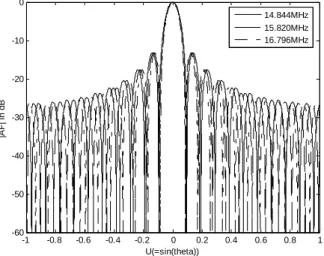
Arrays of broadband signals have been applied in sonar, radio, radar, acoustic imaging etc. These are often difficult to design because of highly frequency dependent array properties. Figure 3 shows the directivity pattern of a simple 21 element linear array. The figure shows, the mainlobe width decreases with increase in frequency. This causes, some signals to be received with distorted spectra, and also frequency – dependent null locations impair the ability to cancel broadband interference. Figure 4 shows the change in interference rejection capability of an adaptive array with input frequency.
delay elements are being replaced with digital filters. In the literature many authors carried out investigations on the design and analysis of broadband beamformers. A class arrays with frequency invariant beam patterns [4, 5, 7, 14, 16, 12], for which a systematic method has been proposed by Ward et.al [5] and can be applied to one – dimensional (1 – D), two dimensional (2 – D) and three – dimensional (3 – D) arrays. Thomas Chou [14] proposed a digital implementation of beamformer covering audio frequencies by using frequency nesting and filter – and – sum beamforming methods. The implementation of broadband beamformer at radio frequencies by using filter – and – sum beamformer was described by Srinivasa rao et.al [12].
The technique to design beamspace adaptive array antenna to suppress interference signals has been proposed by a number of authors [8 – 11]. Every design reported by authors had advantages one over the other and in common they require few adaptive weights compared to tapped – delay – line circuits.
In this paper, we propose a beamspace adaptive array designed by using simple digital filterers to suppress interference signals. Our proposed method is very simple to design, gives better Signal to Interference Rejection Ratio (SINR) and it has the property of much faster convergence.
2. Beamforming Theory
For a linear array, the far field response for an input frequency ω and incident angle θ (measured relative to broadside) is given by [7]:
(
)
∞
(
)
∞ −
−
= x Dx dx
c j
Pθ,ω exp ωsinθ ,ω
(1)
where cand θ are the propagation speed and angle of impinging signal and D
(
x,ω)
the frequency response with respect to the angular frequencyω
and location x. Obviously, in general P(
ω,θ)
is a function of bothω
andθ, while for a frequency invariant beamformer, we require that the beam pattern P(
ω,θ)
be independent ofω
.For a weighted linear array of2N+1 equally spaced omnidirectional elements, the far field response can be represented from the above equation (5):
(
)
(
)
(
) (
)
− = −
=
− =
− =
N
N n N
N n
x D jn
x D x c j
Pθ,ω exp ωsinθ ,ω exp ωτ0sinθ ,ω (2)
where, τ0 =d cis the interelement spacing divided by the speed of wave and D
(
x,ω)
is the response of the filter connected to antenna element at x.Inter null beamwidth of a uniformly excited linear array is given by [4]:
(
0)
01
4 2
sin
2 π ωτ π ωτ
θBW = M ≈ M
−
(3) where,M =2N+1. This expression clearly indicates that the beamwidth of an array was inversely proportional to frequency. It implies that an increase in either the number of elements or interelement spacing results in a decrease in the beamwidth as well.
3. Adaptive Array Antenna for Broadband Signals
3.1 Structure of the Beamspace Linear Array Antenna for Broadband Signals:
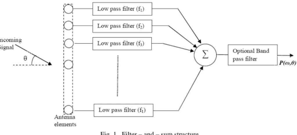
The frequency – variations within the octave are then controlled by the frequency – dependent element weights implemented by a filter – and – sum beamformer structure [14] as shown in the Figure 1.
Fig. 1. Filter – and – sum structure
3.1 Proposed Structure of the Beamspace Adaptive Array Antenna for Broadband Signals
Figure 2 shows the proposed beamspace adaptive array antenna for broadband signals. In this structure, a digital multibeam network that can pass the broadband signal and adaptive weights follow the beam selector to reject the interference signals.
Fig. 2. Proposed structure of the beamspace adaptive array antenna for broadband signals
3.2 Design Method
The following procedure was used to implement filters used in adaptive array:
Step 1: The linear array geometry has to be determined. Inter – element spacing must be at most 0
4f c
d= to avoid aliasing. Where cis speed of wave propagation and f0 is lower frequency of operation required for antenna array.
Step 2: A set of frequency values can be calculated as f1,f2,f3fKsuch that f1 = f0, fK =2f0, where K=
(
N+1)
2 and the remaining values are uniformly distributed in the range[
f0,2f0]
. So, the cutoff frequencies of filters connected to antenna elements on the array in the orderf1,f2,f3fK,f3,f2,f1.Step 3: For each element, many well – known FIR filter design methods were available to design the filters; for the frequency response constraints determined in step 2.
[ ]
[ ] [ ]
[ ]
[ ]
[ ]
[
n]
w[ ]
n x[ ] [ ]
n n wWeight
n y n d n e Error
n x n w n y
Output H
*
1 = +µ ε
+ − = =
(4)
where μ is a gain constant and control the rate of adaptation. The adaptive algorithm is not limited to the LMS, but in the paper LMS algorithm was used to generate computer simulations.
4. Simulations
4.1 Conditions of Simulation
We assume that antenna array was uniformly spaced and each antenna element has an omnidirectional pattern and no mutual coupling. Table 1 gives basic design parameters used for designing of the antenna. Table 2, gives the details of radio environment used in computer simulation.
Table 1. Basic design parameters
Number of Antenna elements 15
Gain constant μ 0.00015
Sampling frequency fc 200 MHz
Type of filter FIR Low pass filter
Order of the filter 100
Table 2. Radio environment used in computer simulation
Direction of arrival SNR/SINR Kind of signal Desired signals
MHz
f1=14.844 90º -- Sinusoidal
MHz
f2 =15.820 90º -- Sinusoidal
MHz
f3 =16.796 90º -- Sinusoidal
Interference signals
Case1 Case 2 Case 3
Interference 1 (I1) - 60 - 60 - 75 - 10 dB Gaussian
Interference 2 (I2) - 30 - 45 - 45 - 10 dB Gaussian
Interference 3 (I3) 30 30 45 - 10 dB Gaussian
Interference 4 (I4) 60 45 60 - 10 dB Gaussian
Noise -- - 10 dB Gaussian
4.2 Results
-1 -0.8 -0.6 -0.4 -0.2 0 0.2 0.4 0.6 0.8 1
-60 -50 -40 -30 -20 -10 0
U(=sin(theta))
|A
F
| i
n
d
B
14.844MHz 15.820MHz 16.796MHz
-80 -60 -40 -20 0 20 40 60 80 -100
-90 -80 -70 -60 -50 -40 -30 -20 -10 0
Theta (degrees)
R
e
s
p
ons
e i
n d
B
Response of 15 element narrowband adaptive antenna with interference signals at -60, -30, 30, 60 degrees
14.844MHz 15.820MHz 16.796MHz
Figure 4. Response of a narrowband adaptive array at interference signals [- 60º, - 30º, 30º, 60º]
-80 -60 -40 -20 0 20 40 60 80
-100 -90 -80 -70 -60 -50 -40 -30 -20 -10 0
Theta (degrees)
R
e
s
p
ons
e i
n d
B
Response of 15 element wideband adaptive antenna with interference signals at -60, -30, 30, 60 degrees
14.844MHz 15.820MHz 16.796MHz
Figure 5. Response of a wideband adaptive array at interference signals [- 60º, - 30º, 30º, 60º]
-80 -60 -40 -20 0 20 40 60 80
-100 -90 -80 -70 -60 -50 -40 -30 -20 -10 0
Theta (degrees)
R
e
s
p
ons
e i
n d
B
Response of 15 element narrowband adaptive antenna with interference signals at -60, -45, 30, 45 degrees
14.844MHz 15.820MHz 16.796MHz
-80 -60 -40 -20 0 20 40 60 80 -100
-90 -80 -70 -60 -50 -40 -30 -20 -10 0
Theta (degrees)
R
e
s
p
ons
e i
n d
B
Response of 15 element wideband adaptive antenna with interference signals at -60, -45, 30, 45 degrees
14.844MHz 15.820MHz 16.796MHz
Figure 7. Response of a wideband adaptive array at interference signals [- 60º, - 45º, 30º, 45º]
-80 -60 -40 -20 0 20 40 60 80
-100 -90 -80 -70 -60 -50 -40 -30 -20 -10 0
Theta (degrees)
R
e
s
p
ons
e i
n d
B
Response of 15 element narrowband adaptive antenna with interference signals at -75, -45, 45, 60 degrees
14.844MHz 15.820MHz 16.796MHz
Figure 8. Response of a narrowband adaptive array at interference signals [- 75º, - 45º, 45º, 60º]
-80 -60 -40 -20 0 20 40 60 80
-100 -90 -80 -70 -60 -50 -40 -30 -20 -10 0
Theta (degrees)
R
e
s
p
ons
e i
n d
B
Response of 15 element wideband adaptive antenna with interference signals at -75, -45, 45, 60 degrees
14.844MHz 15.820MHz 16.796MHz
-80 -60 -40 -20 0 20 40 60 80 -100
-90 -80 -70 -60 -50 -40 -30 -20 -10 0
Theta (degrees)
R
e
s
p
ons
e i
n d
B
Response of 15 element wideband adaptive antenna with interference signals at -60, -30, 30, 60 degrees for 100 iterations
14.844MHz 15.820MHz 16.796MHz
Figure 10. Response of a wideband adaptive array at interference signals [- 60º, - 30º, 30º, 60º] for iterations 100
-80 -60 -40 -20 0 20 40 60 80
-100 -90 -80 -70 -60 -50 -40 -30 -20 -10 0
Theta (degrees)
R
e
s
p
ons
e i
n d
B
Response of 15 element wideband adaptive antenna with interference signals at -60, -30, 30, 60 degrees for iterations 200
14.844MHz 15.820MHz 16.796MHz
Figure 11. Response of a wideband adaptive array at interference signals [- 60º, - 30º, 30º, 60º] for iterations 200
-80 -60 -40 -20 0 20 40 60 80
-100 -90 -80 -70 -60 -50 -40 -30 -20 -10 0
Theta (degrees)
R
e
s
p
ons
e i
n d
B
Response of 15 element wideband adaptive antenna with interference signals at -60, -30, 30, 60 degrees for iterations 500
14.844MHz 15.820MHz 16.796MHz
Table 3. Wideband adaptive antenna response for interference signals Interference rejection in dB
Case1 Case 2 Case 3
1
f f2 f3 f1 f2 f3 f1 f2 f3
Interference 1 (I1) -74.13 -67.73 -61.01 -79.41 -70.57 -58.15 -81.65 -67.93 -61.11
Interference 2 (I2) -71.85 -70.95 -57.2 -80.84 -67.93 -56.37 -76.28 -64.3 -68.51
Interference 3 (I3) -68.84 -62.92 -76.33 -73.65 -65.93 -57.61 -61.97 -60.75 -76.2
Interference 4 (I4) -66.22 -63.95 -74.01 -72.28 -71.69 -79.78 -55.21 -75.55 -68.62
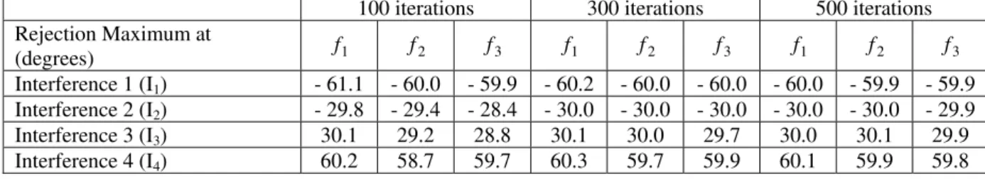
Table 4. Change in wideband adaptive antenna response with respect to no. of iterations
100 iterations 300 iterations 500 iterations Rejection Maximum at
(degrees) f1 f2 f3 f1 f2 f3 f1 f2 f3
Interference 1 (I1) - 61.1 - 60.0 - 59.9 - 60.2 - 60.0 - 60.0 - 60.0 - 59.9 - 59.9
Interference 2 (I2) - 29.8 - 29.4 - 28.4 - 30.0 - 30.0 - 30.0 - 30.0 - 30.0 - 29.9
Interference 3 (I3) 30.1 29.2 28.8 30.1 30.0 29.7 30.0 30.1 29.9
Interference 4 (I4) 60.2 58.7 59.7 60.3 59.7 59.9 60.1 59.9 59.8
5. Conclusions
In this paper, a new wide-band adaptive array processing structure was presented using the filter – and – sum beam forming method. We demonstrated by computer simulation the possibility of suppressing wideband interference signals as well as a much faster convergence speed, of our proposed method. Design examples considered in Table 3 and results presented in Figure 4 to 9, shows that it can achieve a satisfactory interference rejection and frequency invariant response over the frequency range of interest. From Table 4 and from Figure 10 to 12, it is observed that the desired interference rejection is obtained within less than 300 iterations and the null levels more than 55 dB lower than the main beam level.
References
[1] Applebaum Sidney P. (1976): Adaptive Arrays, IEEE Transactions on Antennas and Propagation, 24(5), pp. 585 – 598.
[2] Er M. H. and Cantoni A. (1985): On an Adaptive Antenna Array Under Directional Constraint, IEEE Transactions on Acoustics, Speech, and Signal Processing, 33(4), pp. 1326 – 1328.
[3] Gabriel William F. (1992): Adaptive Processing Array Systems, Proceedings of the IEEE, 80(1), pp. 152 – 162.
[4] Goodwin. M. M., Elko G. W. (1993): Constant beamwidth beamforming, in Proc. IEEE International Conference on Acoustics, Speech, and Signal Processing, Minneapolis, MN, USA, 1, pp.169 – 172.
[5] John H. Doles, III and Frank D. Benedict (1988): Broad-Band Array Design Using the Asymptotic Theory of Unequally Spaced Arrays, IEEE Transactions on Antennas and Propagation,36(1), pp. 27 – 33.
[6] Lamont Frost III O. (1972): An Algorithm for Linearly Constrained Adaptive Array Processing, Proceedings of the IEEE, 60(8), pp. 926 – 935.
[7] Liu W. and Weiss S. (2004): A new class of broadband arrays with frequency invariant beam patterns, in Proc. IEEE International Conference on Acoustics, Speech, and Signal processing, Montreal, Canada, 2, pp. 185 – 188.
[8] Liu W., Wu R. B. and Langley R. (2006): Analysis and a Novel Design of the Beamspace Broadband Adaptive Array, Progress In Electromagnetics Research Symposium, USA, pp. 368 – 373.
[9] Liu Wei, Wu Renbiao, and Langley Richard J. (2007): Design and Analysis of Broadband Beamspace Adaptive Arrays, IEEE Transactions on Antennas and Propagation, 55(12), pp. 3413 – 3420.
[10]Sekiguchi MiuraTakashi, Ryu and Karasawa Yoshio (1996): Beamspace Adaptive Array Antenna for Broadband Signals, Proceedings of ISAP, CHIBA, JAPAN, pp. 761 – 764.
[11]Sekiguchi T akashi and KarasawaYoshio (2000): Wideband Beamspace Adaptive Array Utilizing FIR Fan Filters for Multibeam Forming,” IEEE Transactions on Signal Processing, 48(1), pp. 277 – 2840.
[12]Srinivasa rao A. S., Mallikarjuna rao P., Muralidhar P. V. and Nayak S. K. (2010): Frequency Invariant beampatterns Using Fractional Fourier Transform, International J.of Multidispl. Research & Advcs. in Engg. (IJMRAE),2(II),pp.123-134. [13]Takao Kazuaki, Fujita Masaharu and Nishi Takashi (1976): An Adaptive Antenna array under Directional Constraint,” IEEE
Transactions on Antennas and Propagation, 24(5), pp. 662 – 669.
[14]Thomas Chou (1995): Frequency – Independent Beamformer with low response error, Proc. IEEE International Conference on Acoustics, Speech, and Signal Processing, Detroit, USA, 5, pp. 2995 – 2998.
[15]Widrow B., Mantey P. E., Griffiths L. J., and Goode B. B. (1967): Adaptive Antenna Systems, Proceedings of the IEEE, 55(12), pp. 2143 – 2159.
![Figure 4. Response of a narrowband adaptive array at interference signals [- 60º, - 30º, 30º, 60º]](https://thumb-eu.123doks.com/thumbv2/123dok_br/15716072.122192/5.892.273.604.109.381/figure-response-narrowband-adaptive-array-interference-signals-º.webp)
![Figure 8. Response of a narrowband adaptive array at interference signals [- 75º, - 45º, 45º, 60º]](https://thumb-eu.123doks.com/thumbv2/123dok_br/15716072.122192/6.892.270.602.422.695/figure-response-narrowband-adaptive-array-interference-signals-º.webp)
![Figure 10. Response of a wideband adaptive array at interference signals [- 60º, - 30º, 30º, 60º] for iterations 100](https://thumb-eu.123doks.com/thumbv2/123dok_br/15716072.122192/7.892.273.601.109.383/figure-response-wideband-adaptive-array-interference-signals-iterations.webp)