Mech. Sci., 7, 201–208, 2016 www.mech-sci.net/7/201/2016/ doi:10.5194/ms-7-201-2016
© Author(s) 2016. CC Attribution 3.0 License.
Configuration synthesis of generalized deployable units
via group theory
Tuanjie Li1, Jie Jiang2, Hangjia Dong1, and Lei Zhang1
1School of Electromechanical Engineering, Xidian University, Xi’an, 710071, China 2Engineering College, Honghe University, Mengzi, 661100, China
Correspondence to:Tuanjie Li ([email protected])
Received: 2 April 2016 – Revised: 28 May 2016 – Accepted: 9 September 2016 – Published: 15 September 2016
Abstract. The generalized deployable mechanism is composed of generalized links and generalized kinematic pairs. The generalized links include the flexible members, springs, and cables etc. The generalized kinematic pairs include the preloaded kinematic pairs and flexible hinges etc. The generalized deployable mechanism consists of generalized deployable units. Based on group theory, this paper presents a brief and effective con-figuration synthesis method for generalized deployable units which is composed of generalized links and gen-eralized kinematic pairs expressed by group. The permutation group is used to obtain all the permutation types of generalized kinematic pairs and generalized links. The configuration matrix of generalized deployable unit is established through combining permutation group, and the topological configurations of generalized deployable units are created. The combining rules of groups are developed. The method of isomorphism detection is used to ensure the uniqueness of configurations. The configurations of generalized deployable units including four and six generalized links are generated respectively.
1 Introduction
The deployable mechanism is proposed by Pinero in the 1960s (Pinero, 1962). Deployable mechanisms, also named as deployable structures (Pellegrino, 2001), can vary their shape automatically from a compact, packaged configuration to an expanded, operational configuration. The first properly engineered deployable structures were used as stabilization booms on early spacecraft. Later on, more complex struc-tures were devised for solar arrays, communication reflectors and telescopes (Li, 2014; Tibert, 2002; Mruthyunjaya, 2003). In other fields there have been a variety of developments, in-cluding retractable roofs for stadia, foldable components for cars, portable structures for temporary shelters and exhibi-tion displays. Obviously, the requirements that have to be met by a deployable mechanism in its operational configu-ration (e.g. providing shelter from rain, in the case of um-brella, or forming an accurate reflective surface, in the case of a deployable reflector antenna for telecommunications) are different from the requirements in the package configuration (usually, this should be as small as possible). But an
essen-tial requirement is that the deployment and retraction trans-formation process should be possible without any damage, and should be autonomous and reliable (Pellegrino, 2001). For this purpose, the deployable mechanisms are composed of same deployable units due to modular design. The deploy-able and folddeploy-able transformation of deploydeploy-able units depends on the elastic deformation of springs, flexible components or cable driven. Thus, the deployable unit not only includes the traditional rigid links and kinematic pairs, but also includes the flexible components, springs, cables and the preloaded kinematic pairs and flexible hinges etc, and thus defined as the generalized deployable unit which is composed of gen-eralized links and gengen-eralized kinematic pairs. The general-ized links include flexible members, springs, and cables etc. The generalized kinematic pairs include preloaded kinematic pairs and flexible hinges etc.
202 T. Li et al.: Configuration synthesis of generalized deployable units via group theory
been one of hotspot issues. The early configuration synthe-sis mainly depended on the experience and inspiration. Until the 1960s, the topological graph theory was introduced to describe the mechanisms and lots of configuration synthe-sis methods were advanced (Davies, 1966). For the deploy-able mechanisms, Gantes (1991) investigated the geometric modeling and design methodology of deployable structures featuring stable and stress-free states in both the deployed and the collapsed configurations. Warnaar and Chew (1995a, b) studied the generation of deployable truss modules with the aid of graph theory. Chen and You (2009) conducted lots of researches in the field of monocyclic constraint mecha-nisms on the basis of Bennett and Myard mechamecha-nisms, and generated some new space deployable mechanisms. Ding et al. (2013) proposed a novel deployable mechanism based on polyhedral linkages, and discussed the mobility and the sin-gularities. Lu et al. (2014) proposed a family of novel deploy-able prism mechanisms based on the Hoekens straight-line linkages. Lu et al. (2015) researched a network of type III Bricard linkages, and performed two methods of connecting linkages. As an expansion of traditional deployable mecha-nisms consisted of rigid links and kinematic pairs, the alized deployable mechanism, which is composed of gener-alized links and genergener-alized kinematic pairs, is a system that can vary their shape automatically from a compact, packaged configuration to an expanded, operational configuration. The generalized links, as the expansion of the traditional rigid links, contain all members which are capable to transform motions and forces, including the flexible members, springs, and cables etc. The generalized kinematic pairs, as the ex-pansion of the traditional pairs, contain all kinematic pairs which connect different links and offer motion constraints, including not only traditional prismatic pairs and revolute pairs but also preloaded prismatic pairs, preloaded revolute pairs, flexible hinges etc. The combination of different gen-eralized links and gengen-eralized kinematic pairs may generate all sorts of configurations with different performances. The structural complexity of generalized deployable mechanisms results in that the topological representation and configura-tion synthesis cannot be addressed by the existing methods. Proceeding from the generalized links and generalized kine-matic pairs, we develop the configuration synthesis of gener-alized deployable units based on the finite group theory. The configurations of generalized deployable units including four and six generalized links are created.
2 Graphical representation and configuration matrix of generalized deployable units
The generalized deployable units include cables, flexible components, and preloaded kinematic pairs etc. The adja-cent matrix of graph theory is often used to describe topo-logical relationship between links and kinematic pairs. Thus, the configuration matrix of generalized deployable units is
( )
×=
≠
⎧
⎪
=
⎨
=
⎪
⎩
0
⎡
⎤
⎢
⎥
⎢
⎥
=
⎢
⎥
⎢
⎥
⎣
⎦
ϕ
= →
=
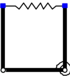
Figure 1.The four-link generalized deployable unit.
defined to describe the topological relationship between gen-eralized links and gengen-eralized kinematic pairs. The diagonal elements in configuration matrix represent the type of gener-alized links, and the nondiagonal elements represent the type of generalized kinematic pairs. The weighted values in the configuration matrix are defined to express the types of gen-eralized links and gengen-eralized kinematic pairs, as shown in Tables 1 and 2.
In order to express the relation between the generalized links and generalized kinematic pairs, the configuration ma-trix is introduced to describe the generalized deployable units. The configuration matrix and the generalized deploy-able unit are one to one correspondence. The diagonal el-ements of configuration matrix represent generalized links, and other elements represent the relation between two gener-alized links. We have
A= aij
n×n, (1)
where,Ais the configuration matrix of a generalized deploy-able unit,nis the number of generalized links, and
aij=
w1 Ifi6= j,the weighted value of generalized kinematic pair connecting two links.
w2 Ifi=j,the weighted value of generalized link. 0 Otherwise.
For example, a four-link generalized deployable unit is shown in Fig. 1, its configuration matrix is
A=
3 9 0 9
9 1 7 0
0 7 1 5
9 0 5 1.
3 Configuration synthesis method
T. Li et al.: Configuration synthesis of generalized deployable units via group theory 203
Table 1.Types of generalized links.
Generalized links Weighted values (w2) Graphical representation
Rigid link 1
Flexible link 2
Spring 3
Cable 4
Table 2.Types of generalized kinematic pairs.
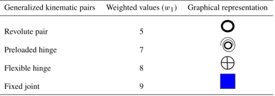
Generalized kinematic pairs Weighted values (w1) Graphical representation
Revolute pair 5
Preloaded hinge 7
Flexible hinge 8
Fixed joint 9
of non-main-diagonal elements of initial matrix constitute a vector called as the kinematic pairs generator b. The vec-tor groups of links and kinematic pairs are obtained from their generators by the defined generation relation. The ma-trix groups of links and kinematic pairs are established by the defined mapping relation. The configuration matrix groups are generated by combining the matrix groups of links and kinematic pairs. The generalized deployable units are cre-ated after removing the unreasonable configurations such as the locally rigid configurations, the unreasonable stress con-figurations and isomorphism concon-figurations.
3.1 Vector groups of links and kinematic pairs
The vector groups of links and kinematic pairs are estab-lished by the defined generation relation for the generators. All the elements of link generator are 1, which means all the links are rigid. All the elements of kinematic pair generator are 5, which means all the kinematic pairs are revolute pairs. The generation relation of links is defined as follows.
ϕ(i, h)= [1→i, h], i=1,2,3,4, (2)
where, idenotes as the generation relation number and the weighted values of links. Thehstands for thehth element in the generator. Equation (2) transforms the weighted value of thehth element in the generator from 1 (rigid link) toi(other type).
Similarly, the generation relation of kinematic pairs is de-fined as follows.
ψ(iY, h)= [5→iY, h], iY =5,7,8,9, (3)
where,iY represents the generation relation number and the weighted value of kinematic pairs.
For example, the generatora=[1,1,1] means that all the links are rigid. The operation ofϕ(2,4)→ameans the gen-eration relationϕ(2,4)= [1→2,4] is applied toa, andais then transformed into [1,1, 2]. That is, the four rigid links are transformed into three rigid links and one flexible link.
The vector subgroups of links and kinematic pairs can be obtained while the generation relations are operated for the generators which is realized with a recursive function. The vector subgroups of links are generated as follows:
G1=ϕ(i,1)→a (4)
Gk=ϕ(i, k)→Gk−1(h), k >1, (5)
wherekis the subgroup number.
The vector subgroups of kinematic pairs are generated as follows.
Y1=ψ(iY,1)→b (6)
Yk=ψ(iY, k)→Yk−1(h), k≫1. (7)
A series of subgroups of links and kinematic pairs are ob-tained in accordance with the above recursive functions. Ev-ery subgroup is a part of configurations, so all the configu-rations are the union of subgroups. The same configuration may exist in the different subgroups, which can be found by the intersection of subgroups. Thus, the vector groups of links and kinematic pairs are derived respectively as follows.
Gs= m [
k=1
Gk−
m(m−1) [
ℓ=1,δ=1,ℓ6=δ n
Gδ \
Gℓ o
(8)
Ys= n [
k=1
Yk−
n(n−1) [
ℓ=1,δ=1,ℓ6=δ n
Yδ \
Yℓ o
Figure 2.Configurations of 4-link generalized deployable unit.
where,mdenotes the number of link subgroups, andnmeans the number of kinematic pair subgroups.
The first items in right side of Eqs. (8) and (9) are the union of all subgroups, and the second items are the intersections of
any two subgroups. The subtraction of two items elimilates isomorphic configurations.
T. Li et al.: Configuration synthesis of generalized deployable units via group theory 205
Figure 3.Planar 6-bar frame structure.
links. A permutation group of a setAdenoted asS(A), is a set of permutations ofAthat forms a group under composition of functions (Kurzweil and Stellmacher, 2004; Richard, 2009). It is the full permutation of elements in a group. Thus, the full-permutation vector groups of links and kinematic pairs are derived respectively as follows:
G=S(Gs) (10)
Y =S(Ys). (11)
3.2 Configuration matrix groups of links and kinematic pairs
First, the two mapping relationships are defined as follows:
1. Ap=J[G(p)], the operatorJ means thepth vector of
Gis placed at the main diagonal of matrixAp, and the others elements of matrixApare zeros.
2. Bq=H[Y(q)], the operatorH means theqth vector of Yare placed the same location as the kinematic pairs of initial matrix, and the other elements of matrix Bq are zeros.
It can be noted that the dimension of matrixes Ap and Bq is the same as that of initial matrix. By the two mapping re-lationships, the full-permutation vector groups of links and kinematic pairs are transformed into the configuration matrix groups of links and kinematic pairs, respectively. They are AL=A1,· · ·,Ap,· · ·,Av andBK=
B1,· · ·,Bq,· · ·,Bw . The addition ofApandBqcan create a configuration matrix, that is
Cpq=Ap+Bq(p=1,· · ·, v; q=1,· · ·, w). (12)
Then, the configuration matrix group is generated as follows.
C=
C11,· · ·,C1q,· · ·,Cpq,· · ·,Cvw . (13)
It can be seen that an element of groupCcorresponds to a configuration matrix of a generalized deployable unit.
3.3 Removing the unreasonable configurations and isomorphism detection
The unreasonable configurations may exist in the configura-tion matrix group. In order to remove the unreasonable con-figurations, we propose some synthesis rules as follows.
1. The bars are replaced sequentially by flexible links, springs, or cables, respectively.
2. The rotational and cylindrical kinematic pairs are re-placed by the preloaded hinges, flexible hinges, or fixed joints, respectively.
3. The fixed joint cannot connect two bars.
4. The preloaded hinge is composed of a torsional spring and a pair, which can only connect two bars.
5. The flexible hinge can connect two bars, two flexible links, a bar and a flexible link, respectively.
6. The connections between two springs, two cables, or a spring and a cable cannot exist.
The above synthesis rules can be performed based on the in-formation of configuration matrix of generalized deployable units. In addition, Li et al. (2011) have proposed the method of the powers of the adjacency matrix for identifying the iso-morphism of topological graphs and weighted multicolored graphs conveniently, correctly and uniquely. Thus the powers of configuration matrix are used to identify the isomorphism configurations of generalized deployable units.
4 Configurations of 4-link and 6-link generalized deployable units
First, the proposed synthesis method is illustrated by the con-figuration generation of 4-link generalized deployable unit by taking the planar four-bar kinematic chain as the initial configuration.
The synthesis process is as follows:
1. The links generator isa= [1,1,1,1], and the kinematic pairs generator isb= [5,5,5,5].
2. The vector subgroups of generalized links can be ob-tained from Eqs. (4) and (5) as
G1= {[1,1,1,1],[2,1,1,1],[3,1,1,1],[4,1,1,1]} (14)
G2= {[1,1,1,1],[1,2,1,1],[1,3,1,1],[1,4,1,1],
[2,1,1,1],[2,2,1,1],[2,3,1,1],[2,4,1,1],
[3,1,1,1],[3,2,1,1],[3,3,1,1],[3,4,1,1],
[4,1,1,1],[4,2,1,1],[4,3,1,1],[4,4,1,1]}
· · · (15)
Meanwhile, the vector subgroups of kinematic pairs can be obtained from Eqs. (6) and (7) as
Y1= {[5,5,5,5],[7,5,5,5],[8,5,5,5],[9,5,5,5]} (16)
Y2= {[5,5,5,5],[5,7,5,5],[5,8,5,5],[5,9,5,5],
[7,5,5,5],[7,7,5,5],[7,8,5,5],[7,9,5,5],
Figure 4.Configurations of 6-link generalized deployable unit with the rigid peripheral four links.
[9,7,5,5],[9,8,5,5],[9,9,5,5]}
· · · (17)
3. The isomorphic configurations of generalized links and kinematic pairs can be eliminated according to Eqs. (8) and (9), and the vector groups of generalized links and kinematic pairs are obtained as follows.
Gs= {[1,1,1,1],[2,1,1,1],[3,1,1,1],[4,1,1,1],
[1,2,1,1],[1,3,1,1],[1,4,1,1],[2,1,1,1],
[2,2,1,1],[2,3,1,1],[2,4,1,1],[3,1,1,1],
[3,2,1,1],[3,3,1,1],[3,4,1,1],· · ·} (18)
Ys= {[5,5,5,5],[7,5,5,5],[8,5,5,5],[9,5,5,5], [5,7,5,5],[5,8,5,5],[5,9,5,5],
[7,7,5,5],[7,8,5,5],[7,9,5,5],
[8,7,5,5],[8,8,5,5],[8,9,5,5],· · ·}. (19)
4. The configuration matrix groups of links and kinematic pairs are established respectively, as
T. Li et al.: Configuration synthesis of generalized deployable units via group theory 207
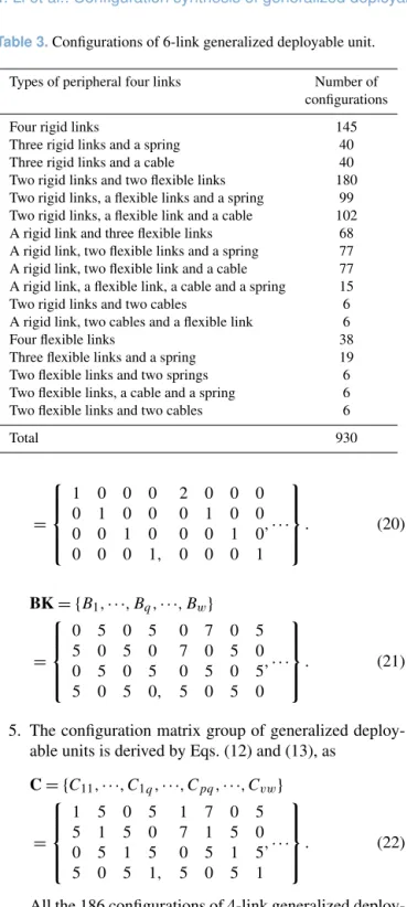
Table 3.Configurations of 6-link generalized deployable unit.
Types of peripheral four links Number of configurations
Four rigid links 145
Three rigid links and a spring 40 Three rigid links and a cable 40 Two rigid links and two flexible links 180 Two rigid links, a flexible links and a spring 99 Two rigid links, a flexible link and a cable 102 A rigid link and three flexible links 68 A rigid link, two flexible links and a spring 77 A rigid link, two flexible link and a cable 77 A rigid link, a flexible link, a cable and a spring 15 Two rigid links and two cables 6 A rigid link, two cables and a flexible link 6
Four flexible links 38
Three flexible links and a spring 19 Two flexible links and two springs 6 Two flexible links, a cable and a spring 6 Two flexible links and two cables 6
Total 930 =
1 0 0 0 2 0 0 0
0 1 0 0 0 1 0 0
0 0 1 0 0 0 1 0
0 0 0 1, 0 0 0 1
,· · · . (20)
BK= {B1,· · ·, Bq,· · ·, Bw}
=
0 5 0 5 0 7 0 5
5 0 5 0 7 0 5 0
0 5 0 5 0 5 0 5
5 0 5 0, 5 0 5 0
,· · · . (21)
5. The configuration matrix group of generalized deploy-able units is derived by Eqs. (12) and (13), as
C= {C11,· · ·, C1q,· · ·, Cpq,· · ·, Cvw}
=
1 5 0 5 1 7 0 5
5 1 5 0 7 1 5 0
0 5 1 5 0 5 1 5
5 0 5 1, 5 0 5 1
,· · · . (22)
All the 186 configurations of 4-link generalized deploy-able unit are created, as shown in Fig. 2.
Then, the planar 6-bar frame structure, as shown in Fig. 3, is regarded as the initial configuration. All the 930 configu-rations of 6-link generalized deployable unit are created, as shown in Table 3 according to the types of peripheral four links. If the peripheral four links are rigid, the number of configurations is 145, as shown in Fig. 4. Some potential ap-plications of synthesized configurations need to develop in the future. Obviously, the second configuration in Fig. 4 can be assembled into the deployable mechanism of Astromesh antenna (Thomson, 1999).
5 Conclusions
The paper proposes a configuration synthesis method of gen-eralized deployable units composed of gengen-eralized links and generalized kinematic pairs based on the group theory. The permutation group of generalized kinematic pairs and gen-eralized links are established and the topological configu-rations of generalized deployable units are generated. The configurations of generalized deployable units including four and six generalized links are created. The proposed method can also be applied to generate the other configurations of generalized deployable units, which will provide the enough configurations for the innovate design of large deployable mechanisms. The networking method of generalized deploy-able units will become keystone of research in the future.
Acknowledgements. The authors gratefully acknowledge the support of the National Natural Science Foundation of China (grant no. 51375360).
Edited by: X. Ding
Reviewed by: two anonymous referees
References
Chen, Y. and You, Z.: Two-fold symmetrical 6R foldable frame and its bifurcations, Int. J. Solids Struct., 46, 4504–4514, 2009. Davies, T. H. and Crossley, F. E.: Structural analysis of plane
link-ages by Franke’s condensed notation, J. Mechanisms, 1, 171– 183, 1966.
Ding, X. L., Yang, Y., and Dai, J. S.: Design and kinematic analysis of a novel prism deployable mechanism, Mech. Mach. Theory, 63, 35–49, 2013.
Gantes, C.: A design methodology for deployable structures, Ph.D. Thesis, Massachusetts Institute of Technology, 1991.
Kurzweil, H., Stellmacher, B.: The theory of finite groups: An in-troduction, Springer-Verlag, 1–92, 2004.
Li, T. J.: Deployable analysis and control of deployable space an-tenna, Aerosp. Sci. Technol., 18, 42–47, 2014.
Li, T. J., Cao, W. Q., and Yan, T. H.: Applications of graph theory in mechanism analysis, in: Emerging topics on differential geome-try and graph theory, edited by: Lucas, B. and Francois, R., New York, Nova Science Publishers, 1–34, 2011.
Lu, S. N., Zlatanov, D., Ding, X. L., and Molfino, R.: A new family of deployable mechanisms based on the Hoekens linkage, Mech. Mach. Theory, 73, 130–153, 2014.
Lu, S. N., Zlatanov, D., Ding, X. L., Zoppi, M., and Guest, S. D.: A Network of Type III Bricard Linkages, ASME 2015 International Design Engineering Technical Conferences and Computers and Information in Engineering Conference, Boston, Massachusetts, USA, Paper No. DETC2015-47139, 2015.
Mruthyunjaya, T. S.: Kinematic structure of mechanisms revisited, Mech. Mach. Theory, 38, 279–320, 2003.
Pellegrino, S.: Deployable structures, Springer, 1–36, 2001. Pinero, E. P.: Expandable space framing, Progressive Architecture,
Richard, A. B.: Introductory combinatorics, 5th ed., Pearson, New York, 1–52, 2009.
Thomson, M. W.: The Astromesh deployable reflector, IEEE An-tennas Prop., 3, 1516–1519, 1999.
Tibert, G.: Deployable tensegrity structures for space applications, Ph.D. Thesis, Sweden, Royal Institute of Technology, 2002.
Warnaar, D. B. and Chew, M.: Kinematic synthesis of deployable-foldable truss structure using graph theory, part 1: graph genera-tion, J. Mech. Design, 117, 112–116, 1995a.