Simulation and Implementation of
Γ
-
Z Source Inverter
G.V.Sreekanth Reddy*, J.N.Chandrasekhar**
*(M.Tech, Department of EEE, Sri Venk ateswara university College of Engineering , Tirupati
** (Assistant Professor, Department of EEE,Sri Venk ateswara university College of Engineering, Tirupati
ABSTRACT
This venture "Simulation and Implementation of Γ-Z-Source Inverters" is made out of Voltage-sort Γ-Z source inverters are proposed in this letter. They utilize a remarkable Γ-mo lded impedance arrange for boosting their yield voltage notwithstanding their standard voltage buck conduct. Contrasting them and different topologies, the proposed inverters utilize lesser parts and a coupled transformer for delivering the high-pick up and regulation proportion all the wh ile . The got pic k up can be tuned by changing the turns proportion γΓZ of the transformer inside the limited scope of 1 < γΓZ ≤ 2. This prompts to lesser twisting turns at high pick up, as compared to other related topologies.
Keywords
-
Embedded-Z-source, quasi-Z-source, T-source, Trans-Z-source, Z-
source, Γ-Z-source inverters.I.
INTRODUCTION
Advanced power electronic applications, particularly those specifically associated with the fra me work, norma lly require some voltage boosting. Customary voltage-source inverters (VSIs) are along these lines not palatable since they can just stride down voltages. To include support usefulness, dc–dc help converters can be put before the VSIs. Then again, single-stage buck-support inverters can be utilized like the Cuk, SEPIC, and other comparative dc–ac inverters found in [1] and [2]. These inverters however don't have escalated follow-up research. Despite what might be expected, explore in another buck-help inverter, named as the Z-source inverter [3], has developed quickly with its balance, dynamics, control, and measuring considered in [4]– [7]. Its applications to engine drives [8], sunlight based era [9], and electric vehic les [10] have additionally been endeavored utilizing a similar fundamental Z-source impedance organize found in [3].Changes to the essential system just surface in [11]–[14], where their separate upgraded systems are named as improved,quasi-, and inserted Z-source systems. In spite of the fact that named in an unexpected way, these systems are firmly comparable with [15] cla rifying that they contrast just in their source positions. The three systems can in the long run be converged into a solitary non specific system without any progressions acquainted with the quantity of LC co mponents
Z-Source and Trans -Z-Source Inver ters
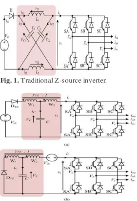
The ma in Z-source inverter proposed in [3] is appeared in Fig. 1, where a one of a kind X-mo lded impedance system can obviously be seen. This additional system permits changes from a similar stage leg to be turned ON all the while without bringing on damages. Instead, the shoot-through state made causes the inverter yield to be
helped without twisting on the off chance that it is utilized legitimately with the other eight Nonshoot-through dynamic and invalid states. The subsequent e xpressions for figuring the system capacitor voltage VC , crest dc-connect voltage vˆi amid the Nonshoot-through state, and top air conditioning yield voltage vˆac can accordingly be determined and
Fig. 1. Traditional Z-source inverter.
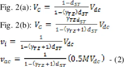
Fig. 2. Trans-Z-source inverters with source placed in series with (a) diode or(b) VSI b ridge written in the following equation:
= ; =
= =
Where Vd c, M , and dST represent the input voltage, modulation rat io, and fractional shoot-through time, respectively.
The boost factor fro m (1) is hence e xp ressed as B= 1Z/ (1 − 2dST ). Setting its denominator to be greater than zero then results in the operating range of 0 ≤ dST < 0.5.
Fig. 2(a):
Fig. 2(b):
- (2)
Since the shoot-through state must be set inside an invalid interim to abstain from presenting volt-sec blunder, relat ionship amongst M and dST can further
be composed as M ≤ 1.15(1 − dST ). To deliver a high-voltage support, M should henceforth be brought down.
Fig. 3.Г-Z-source inverters with source placed in series with (a ) diode or (b) VSI bridge.
Bring down M how-ever pro mpts to high-voltage worries over the segments and poor unearthly exh ibitions. To keep a way fro m these limitat ions, T-source or trans-Z-source inverters are proposed [19], [20]. In like manner, the trans -Z-source inverters appeared in Fig. 2 utilize just a single trans-previous with turns proportion γTZ = W1/W2 and one capacitor. They contrast just in their source situations, whose impact is to differ VC yet not alternate voltages. This can unmistakably be seen from (2), where e xp ressions for processing VC
, vˆi , and vˆac for the trans-Z-source inverters are introduced [20]
Co mparing the denominators of (1) and (2), it is clear that the trans-Z-source gain can be raised above the traditional Z-source gain if γT Z
is set greater than one (γT Z ≥ 1). Fro m (2), the new limits for dST can also be determined as 0 ≤ dST < 1/(γT Z + 1), after setting the denominator of (2) to be greater than zero. Clearly, the upper limit of dST can be reduced by using a higher γT Z for gain boosting. The lower dST then leads to a higher modulation ratio since M ≤1.15(1 − dST).
II. Γ-Z-SOURCE INVERTERS For the trans-Z-source inverters, high pick up is gotten by expanding their regular transformer turns proportion γTZ , which is in concurrence with established transformer hypotheses. Contingent upon the inevitable voltage pick up requested, the raised γTZ may on occasion be over the top for acknowledgment. On account of this, Γ-Z-source inverters attracted Fig. 3 are p roposed in this letter as alternatives. The proposed inverters utilize an indistinguishable parts from the trans -Z-source inverters, however with various transformer situation. This distinction causes the Γ-Z-source pick up to be raised by lowering, and not e xpanding, the transformer turns proportion γΓZ . Scope of γΓZ can in reality be resolved as 1 < γΓZ≤ 2, as showed in the accompanying segment
A. Ste ady-State Expressions
Shoot-Through State: framed by turning ON two changes from a similar stage leg at the same time to short the dc-interface voltage vi to zero. In the meantime, input diode DΓZ blocks, hence offering ascend to the equal circuit appeared in Fig. 4(a).Using this proportional circu it, the accompanying circuit conditions can be written:
Fig. 3(a): ;
(3)
Fig. 3(a):
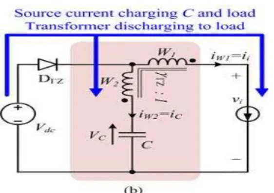
Fig. 4. Equivalent circuits of the Г-Z-source inverter in Fig. 3(a ) when in(a) shoot-through and (b) non-shoot-through states.
Nonshoot-Through State: Shoot-Through State: fra med by turning ON t wo changes from a similar stage leg at the same time to s hort the dc-interface voltage vi to zero. In the meantime, input diode DΓZ blocks, hence offering ascend to the equal circuit appeared in Fig. 4(a ).Using this proportional circuit, the accompanying circuit conditions can be written:
Fig. 3(a): (5)
Fig. 3(b): (6)
Performing state-space averaging on either winding W2 or W1 then leads to the following two e xpressions for computing capacitor voltage VC:
(7)
(8)
Using (7) and (8), the peak dc-link voltage vˆi during the Nonshoot-through interval and peak ac output voltage vˆac can be determined as (9) and (10) for the two inverters shown in Fig. 3
(9)
(10)
These equations are closely similar to those of the trans-Z-source inverters listed in (2). They are in fact the same if their respective turn’s ratios are set according to the following equation:
or (11)
Producing a gain higher than the traditional Z-source inverter shown in Fig. 1 would hence require γTZ to be greater than 1 (γTZ ≥ 1) for the trans-Z-source inverters, and γΓZ to be reduced from 2 to 1 for the Γ-Z-source inverters (1 < γΓZ ≤2). At high gain, γTZ might hence be excessive (γTZ → ∞ in the ideal case), while γΓZ approaches 1. The former might result in more turns for the trans -Z-source inverters especially when sufficient number of turns is needed for their low voltage W2 winding for ma intaining tight coupling. The proposed Γ -Z-source inverters, on the other hand, can have their
transformer wound on a core with high nH/t2 (t stands for turns) to keep their wind ing turns low [21]. These possibilities and ratio tuning range (1 < γΓZ ≤ 2) of the Γ-Z-source inverters have so far not been identified by other researchers.
B. Tr ansient Expressions
The prior inferred e xpressions are for registering the inverter reactions in the enduring state. To process their transient reactions, little flag investigation exhibited in [22] is connected first to locate the nonstop capacitor voltage variety V ̃C when bothered by an adjustment in shoot -through time D ̃ST in the Laplace space . The subsequent e xpression for the inverters in Fig. 3 is given as
(12)
III. DIFFER ENT APPROACHES B Y US ING DIFFER ENT CONTROLLERS Here various sorts of methodologies are fin ished by utilizing diverse kind of controllers .Here first the outcomes are watched for the open circle circuit which Rise time and Settling time is high,then the circuit is utilized with various controllers like PI controller and Fuzzy controller are utilized and the Output speed,voltage ,speed and Torque wave structures are observed.The out put aftereffects of various controllers are given underneath by utilizing distinctive controllers the change or the distinction in the execution of the fra me work in various cases is seen from this we can watch that the out put is better in shut circle PI controller utilized circuit when contrasted and open circ le fra mewo rk .The circuit in whch we utilized FLC has great yield speed and torque comes about than PI controller
The Rise time,Settling time in various cases will give a thought regarding the execution utilizing distinctive controllers
Here the above wave forms are output speed and
torque wave forms of open loop system
Simulink model of the closed l oop system with PI contr oller:
OUTPUT VOLTAGE WAVEFORM
OUTPUT CURRENT WAVEFORM
SPEED WAVEFORM
TORQUE WAVEFORM
Simulink model of the closed loop system wi th FLC:
OUTPUT VOLTAGE WAVEFORM
SPEED WAVEFORM
TORQUE WAVEFORM COMPARISON TABLE
Controllers Rise T ime(s) Settling Time(s)
Steady state error(rmp)
Open loop 1.25 1.3 -
PI Controller 0.3 0.35 30
FLC 0.25 0.26 -
IV. CONCLUS ION
This venture has exhib ited the methods for the limit and controller outline of the Γ-Z-Source Inverters frame work. Working addition and balance proportion of the Γ-Z-source inverters have been ended up being the same as the trans -Z-source inverters, and thus higher than those of the conventional Z-source inverter. In any case, not at all like the trans -Z-source inverters, pick up increment of the Γ-Z-source inverters is accomplished by dimin ishing, and not expanding, their turns proportion in the scope of 1 < γΓZ ≤ 2. Transformers required by the Γ-Z-source inverters may in this way be littler fo r high-pic k up applications.
The Basic c ircuit and altered circuit components are co mposed utilizing applicable conditions. The reproduction circuits are created utilizing components of Simulink library. The Simu lation is effective ly done and open circle/shut circ le with PI controller and FLC reenact ment results are exhib ited. The Simulat ion comes about agree with the hypothetical outcomes.
REFERENCES
[1] J. Kikuchi and T. A. Lipo, ―Three phase PWM boost -buck rectifiers with power regenerating capability,‖ IEEE T rans. Ind. Appl., vol. 38, no. 5,pp. 1361–1369, Sep./Oct. 2002.
[2] G. Moschopoulos and Y. Zheng, ―Buck-boost type ac-dc single-stage converters,‖ in Proc. IEEE Int. Symp. Ind. Electron., Jul. 2006, pp. 1123–1128.
[3] F. Z. Peng, ―Z-source inverter,‖ IEEE Trans. Ind. Appl., vol. 39, no. 2,pp. 504–510, Mar./Apr. 2003. [4] P. C. Loh, D. M. Vilathgamuwa, Y. S. Lai, G. T .
Chua, and Y. W. Li,―Pulse-width modulation of Z-source inverters,‖ IEEE Trans. Power Electron., vol. 20, no. 6, pp. 1346–1355, Nov. 2005.
[5] J. Liu, J. Hu, and L. Xu, ―Dynamic modeling and analysis of Z-source converter—Derivation of ac small
signal model and design-oriented analysis,‖ IEEE Trans. Power Electron., vol. 22, no. 5, pp. 1786–1796, Sep.2007.
[6] G. Sen and M. E. Elbuluk, ―Voltage and current -programmed modes in control of the Z-source converter,‖ IEEE Trans. Ind. Applicat., vol. 46,no. 2, pp. 680–686, Mar./Apr. 2010.
[7] S. Rajakaruna and L. Jayawickrama, ―Steady-state analysis and designing impedance network of Z-source inverters,‖ IEEE Trans. Ind. Electron.,vol. 57, no. 7, pp. 2483–2491, Jul. 2010.
[8] F. Z. Peng, A. Joseph, J. Wang, M. Shen, L. Chen, Z. Pan, E. Ortiz-Rivera,and Y. Huang, ―Z-source inverter for motor drives,‖ IEEE Trans. Power Electron., vol. 20, no. 4, pp. 857–863, Jul. 2005.
[9] M. Hanif, M. Basu, and K. Gaughan, ―Understanding the operation of a Z-source inverter for photovoltaic application with a design example,‖IET Power Electron., vol. 4, no. 3, pp. 278–287, Mar. 2011. [10] F. Z. Peng, M. Shen, and K. Holland, ―Application of
Z-source inverter for traction drive of fuel cell— Battery hybrid electric vehicles,‖ IEEE Trans. Power Electron., vol. 22, no. 3, pp. 1054–1061, May 2007. [11] Y. Tang, S. Xie, C. Zhang, and Z. Xu, ―Improved Z
-source inverter with reduced Z--source capacitor voltage stress and soft -start capability,‖ IEEE Trans. Power Electron., vol. 24, no. 2, pp. 409–415, Feb. 2009.
[12] J. Anderson and F. Z. Peng, ―A class of quasi-Z-source inverters,‖ in Proc. IEEE Ind. Appl. Soc., Oct. 2008, pp. 1–7.
[13] P. C. Loh, F. Gao, and F. Blaabjerg, ―Embedded EZ -source inverters,‖ IEEE Trans. Ind. Appl., vol. 46, no. 1, pp. 256–267, Jan./Feb. 2010.
[14] [14] F. Gao, P. C. Loh, F. Blaabjerg, and C. J. Gajanayake, ―Operational analysis and comparative evaluation of embedded Z-Source inverters,‖ in Proc. IEEE Power Electron. Spec. Conf., Jun. 2008, pp. 2757–2763.
[15] D. Li, F. Gao, P. C. Loh, M. Zhu, and F. Blaabjerg, ―Hybrid-source impedance networks: Layouts and generalized cascading concepts,‖ IEEE Trans. Power Electron., vol. 26, no. 7, pp. 2028–2040, Jul. 2011. [16] M. Zhu, K. Yu, and F. L. Luo, ―Switched inductor Z
-source inverter,‖ IEEE Trans. Power Electron., vol. 25, no. 8, pp. 2150–2158, Aug. 2010.
[17] M. Zhu, D. Li, P. C. Loh, and F. Blaabjerg, ―Tapped -inductor Z-source inverters with enhanced voltage boost inversion abilities,‖ in Proc. IEEE Int. Conf. Sustainable Energy Technol., Dec. 2010, pp. 1–6. [18] M. Adamowicz, ―LCCT-Z-source inverters,‖ in Proc.
Int. Conf. Environ. Elect. Eng., May 2011, pp. 1–6. [19] R. Strzelecki, M. Adamowicz, N. Strzelecka, and W.
Bury, ―New type T-source inverter,‖ in Proc. Compat.
Power Electron.’09, May 2009, pp. 191–195. [20] W. Qian, F. Z. Peng, and H. Cha, ―Trans-Z-source
inverters,‖ IEEE Trans. Power Electron., vol. 26, no. 12, pp. 3453–3463, Dec. 2011.
[21] Selection table for Molypermalloy Powder (MPP)
cores, Magnetics. (2013). [Online].
Available:http://web2.spangen.prod.bridgelinesw.net/p roducts/powder-cores/mpp-cores
[22] P. C. Loh, D. M. Vilathgamuwa, C. J. Gajanayake, Y. R. Lim, andC. W. Teo, ―Transient modeling and analysis of pulse-width modulated Z source inverter,‖