Tribology
in
Industry
www.tribology.fink.rsDetermination
of
Optimum
Compression
Ratio:
A
Tribological
Aspect
L. Yüksek
a, O. Özener
a,(. Kaleli
aaYıldızTechnicalUniversity,MechanicalEngineeringDepartment,Beşiktaş, İstanbul,Turkey.
Keywords:
Compressionratio Frictionloss Enginetribology
In‐cylinderpressureanalysis
A B S T R A C T
Internalcombustionenginesaretheprimaryenergyconversionmachinesboth inindustryandtransportation.Moderntechnologiesarebeingimplementedto
engines to fulfil today’s low fuel consumption demand. Friction energy
consumed by the rubbing parts of the engines are becoming an important
parameterforhigherfuelefficiency.Rateoffrictionlossisprimarilyaffectedby slidingspeedandtheload actinguponrubbingsurfaces.Compressionratiois themainparameterthatincreasesthepeakcylinderpressureandhencenormal loadoncomponents.
Aimofthisstudyistoinvestigatetheeffectofcompressionratioontotalfriction lossofadieselengine.AvariablecompressionratioDieselenginewasoperated at four different compression ratios which were “12.96”, “15.59”, “18.03”, “20.17”.Brake power andspeed waskept constant atpredefinedvalue while measuring the in‐cylinder pressure. Friction mean effective pressure (FMEP) datawereobtainedfromtheincylinderpressure curvesforeachcompression ratio. Ratiooffrictionpower toindicatedpoweroftheenginewasincreased from22.83%to37.06%withvaryingcompressionratiofrom12.96to20.17. Considering the thermal efficiency, FMEP and maximum in‐cylinder pressure
optimum compression ratio interval of the test engine was determined as
18.8÷19.6.
© Published by Faculty of Engineering Corresponding author:
LeventYÜKSEK
YıldızTechnicalUniversity,
MechanicalEngineering
Department,Beşiktaş, İstanbul,Turkey
E‐mail:[email protected]
1. INTRODUCTION
There has been an increasing demand for reducing fuel consumption of the internal combustion engines )CE . On the other hand, tail‐pipe emission regulations force engine developers to dramatically cut toxic pollutants [ ]. A proper engine calibration for balancing the fuel consumption and exhaust emission has to be maintained [ ]. An optimization is required from the very beginning of the design which comprises the selection of materials, exact
determination of main design parameters, proper component selection and computer based modelling process [ ‐ ]. Developments both in spark ignition S) and compression ignition engines lead to better fuel economy but the limits of further improvements are drawn by the rules of thermodynamic and the science of material [ , ]. Effective heat of fuel is relatively small, unused energy is transferred to coolant as heat or expelled with the combustion products to atmosphere. )mproving the conversion efficiency of fuel by
optimizing the engine operation and design parameters is a substantial issue [ , ]. Compression ratio is an important structural parameter which significantly affects thermal efficiency [ ‐ ]. (igh compression ratios are favourable for S) engines at part load conditions while the cold start improvement is proved for diesel engines [ , , ]. Literature offers significant amount of studies on compression ratio and effects on engine parameters [ ‐ ]. On the other hand, friction is one of the main contributors of the energy loss in )CE where the heat generated from the rubbing surfaces is transferred to the engine lubricant and coolant [ ]. Reduction of engine friction has already have a great potential for
reducing fuel consumption where the
improvements made on combustion science and thermodynamics have almost been reached to limits [ ]. Friction force is a function of normal load and lubrication regime. )n order to reduce friction torque of the )CE without modifying the lubrication system, normal load acted on rubbing surfaces has to be decreased. Normal load acting upon bearings, piston and rings is created by the in‐cylinder pressure and linearly related with the compression ratio of the engine. )n actual engine conditions, the increase of normal load affects the lubrication regime related to Stribeck curve as shown in Fig. [ , ].
Fig.1.Definition of various lubrication regimes with
Stribeck curve.
The higher the compression ratio the more the energy converted to effective work, both in S) and diesel engines theoretically. (owever in actual engine conditions it is rather different than theory due to the detonation phenomena in S) engines and the increase of friction and wear in diesel engines. With considering the up‐coming EU‐ legislative, in‐cylinder peak temperature of modern diesel engines has to be reduced due to lower nitrogen oxides demand [ ]. One possible way to obtain this is to decrease structural compression ratio of the engine, which also leads
to a reduction of friction torque but possible penalty of thermal efficiency has to be considered. Main aim of this study is to investigate the effect of compression ratio on engine friction power at various compression ratios. Secondary objective of this work is to optimize compression ratio with considering the brake power, friction loss and thermal efficiency. A single cylinder research engine with variable compression ratio system was equipped, engine friction, brake power and specific fuel consumption was measured.
2. EXPERIMENTALSETUP
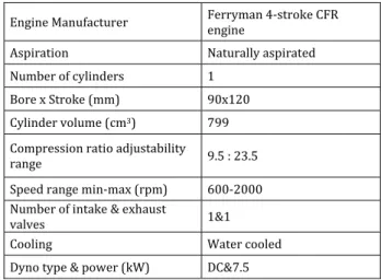
The test bed consisted of a research engine and a direct‐current dynamometer; the test engine can operate as an S) or compression ignition principles, thanks to its variable compression ratio apparatus. Detailed information about the test bed is listed in Table .
Table1. Technical details of test bed and engine.
Engine Manufacturer Ferryman ‐stroke CFR engine Aspiration Naturally aspirated Number of cylinders
Bore x Stroke mm x Cylinder volume cm
Compression ratio adjustability
range . : . Speed range min‐max rpm ‐ Number of intake & exhaust
valves & Cooling Water cooled Dyno type & power kW DC& .
Engine clearance volume can be adjusted by the piston which assembled into cylinder head. Piston movement is driven by a screw type bushing assembly as can be seen in Fig. .
Engine brake torque was measured via a load cell. The fuel consumption was measured with a gear‐type flow meter and the engine coolant temperature was measured with K‐type thermocouples. An incremental encoder with . degree crank angle resolution used for monitoring the engine speed and top dead
center TDC pick up. Kistler B
piezoelectric pressure transducer, Kistler B charge amplifier and LeCroy Wave surfer Xs
channel digital oscilloscope were utilized for measurement and acquisition of the in‐cylinder pressure data. Schematic of the test system is illustrated in Fig. .
Fig.3.Test system.
Engine compression ratio was varied for each test condition. )n order to obtain comparable results, engine speed and brake power were kept constant for all compression ratios. A tabulated data of test conditions are listed in Table .
Table2. Test conditions.
Friction losses of the engine were determined by using in‐cylinder pressure data. )ndicated power of the engine was calculated in post‐mortem analysis. )ndicated work of the system was
calculated with using equation where the differentiation of cylinder volume and pressure are inputs. )nstantaneous cylinder volume of the engine was determined with incremental encoder.
Wind=ɸ pdV
Equation was used to calculate indicated power of the test engine.
ind ind n
W N
P
R
Pfricion=Pind ‐ Pbrake
n friction
d
P
R
FMEP
V N
The difference between indicated power and the measured power is the friction energy consumed by the rubbing parts. Relative friction performance of the engine can easily be compared with the literature by the means of friction mean effective pressure definition FMEP which stated in equation . Auxiliary power consumers on the engine are cooling water pump and fuel pump, which are not affected by the compression ratio and hence it was not necessary to make a change.
Steady‐state test conditions were facilitated for the measurements. Fifty consecutive cycles were logged and then averaged to minimize the effect of cyclic variations.
3. RESULTSANDDISCUSSIONS
Compression ratio is a geometrical design parameter which affects several parameters including construction dimensions, maximum in‐ cylinder pressure, thermal efficiency, tail‐pipe emissions and effective work. )ncreasing compression ratio results higher peak in‐cylinder pressure and hence higher bulk temperature of the charge. Due to stricter nitrogen oxides legislations, lower temperature peaks are required. Additionally, higher end of compression stroke pressure leads to higher thermal efficiency theoretically. )n case of engine tribology, compression ratio induced higher in‐cylinder pressure lead to an increase of the ring‐ liner contact pressure which results higher friction and wear. This phenomenon is one of the main reason that limiting the increase of compression ratio in compression ignition engines.
Compression
Ratio Brake power Generated kW
Engine speed rpm
Brake mean effective pressure
Bars . .
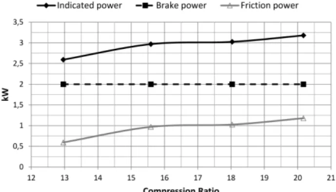
Figure shows the indicated power, brake power generated and the friction power consumed by the test engine. According to pre‐ determined test conditions brake power was kept constant and hence the effect of compression ratio itself exhibited clearly.
Fig. 4. Variation of brake power with respect to
compression ratio.
Almost linear trend was observed both in indicated power and friction power. Ratio of friction power to indicated power of the engine was increased from . % to . % with varying compression ratio from . to . . Additionally thermal efficiency of the test engine was also increased with the increase of compression ratio as illustrated in Fig. .
Fig. 5. Variation of engine thermal efficiency with
respect to compression ratio.
Considering the Figs. and , it can be concluded as the results are in harmony with published literature [ , ]. On the other hand, determining for an optimum compression ratio range with only considering the thermal efficiency would not be so effective. Also, the range has to be investigated from the view of tribological perspective.
Figure shows the in‐cylinder pressure curves depending on the test points. )n spite of equal brake power output, higher component load is
distinct. )n terms of durability, ring‐pack and journal bearing load which directly affected by the in‐cylinder pressure has to be taken into consideration. Friction power curve in figure indicates significant increase when compression ratio varied from . to . which can be related with the lubrication regimes of mentioned components. Also, fluid film thickness was not measured.
Fig.6.)n‐cylinder pressure curves of test points.
)n order to evaluate the frictional loss of the engine, normalized FMEP is calculated with using in‐cylinder pressure data. Optimum compression ratio determination is a multi‐ variable investigation which must comprises thermal efficiency and the component load as input data. Normalized thermal efficiency, FMEP and load acting upon tribological systems are concerned together in Fig. .
Fig. 7. Parameters acting upon the determination
process of optimum compression ratio.
region represents the ideal operation condition for the components while red region indicates the possibility of higher wear. A compromise between high component load and the reduction in thermal efficiency is required, and hence the dashed region in Fig. can be chosen for the range of optimum compression ratio. Primary
criteria while selecting this area is the %
friction reduction corresponds to % thermal efficiency loss which is a good balance point for the initialization of the range. Further increase of compression ratio leads % component load reduction for % thermal efficiency loss, beyond this point, equal reduction in mentioned quantities are observed and hence further increase of compression ratio is not feasible.
From this point of view, compression ratio of a newly designed engine can be adjusted according to the data obtained from the in‐ cylinder pressure. This approach can also be used to limit the peak combustion pressure of new generation supercharged engines.
4. CONCLUSIONS
The aim of this study is to investigate an optimum compression ratio by considering the friction loss and thermal efficiency of an engine. A single cylinder research engine with variable compression ratio was equipped for the tests. Engine brake power and speed was kept constant for all compression ratio experiments. According to test results, with increasing the compression ratio, indicated power and friction power of the test engine was increased linearly. On the other hand, with considering the thermal efficiency, FMEP and maximum in‐cylinder pressure optimum compression ratio interval of the test engine was determined as . ÷ . .
REFERENCES
[ ] T.V. Johnson: VehicularEmissionsinReview, SAE
‐ ‐ , .
[ ] D. Siano, F. Bozza, M. Costa: Reducing Fuel
Consumption, Noxious Emissions and Radiated
NoisebySelectionoftheOptimalControlStrategy
ofaDieselEngine, SAE ‐ ‐ , .
[ ] E.P. Becker: Trendsintribologicalmaterialsand enginetechnology, Tribol )nt,. Vol. , No. , pp.
‐ , .
[ ] K. Gotoh, J. Ceppi, N. Sabatier, Y. Tsuchida: Multi AttributeOptimization:FuelConsumption,Emissions
andDriveability, SAE ‐ ‐ , .
[ ] C.D. Rakopoulos, E.G. Giakoumis: Second‐law analyses applied to internal combustion engines operation, Prog Energ Combust., Vol. , No. , pp. ‐ , .
[ ] B. Saerens, J. Vandersteen, T. Persoons, J. Swevers, M. Diehl, E. Van den Buick:
Minimization of the fuel consumption of a
gasolineengineusingdynamicoptimization, Appl Energ. Vol. , No. , pp. ‐ , .
[ ] J.A. Caton: OperatingCharacteristicsofaSpark‐
Ignition Engine Using the Second Law of
Thermodynamics:EffectsofSpeedandLoad, SAE
‐ ‐ , .
[ ] ).E. Fox: Numericalevaluationofthepotential for fueleconomyimprovementduetoboundaryfriction reduction within heavy‐duty diesel engines, Tribol )nt., Vol. , No. , pp. ‐ , .
[ ] V. Rabhi, J. Beroff, F. Dionnet: Study of a Gear‐
Based Variable Compression Ratio Engine, SAE
‐ ‐ , .
[ ] M. Roberts: Benefits and Challenges of Variable
CompressionRatio(VCR), SAE ‐ ‐ , .
[ ] J.B. (eywood: Internal Combustion Engine
Fundamentals, McGraw‐(ill, .
[ ] F. Mallamo, M. Badami, F. Millo: Effect of
Compression Ratio and Injection Pressure on
Emissions and Fuel Consumption of a Small
Displacement Common Rail Diesel Engine, SAE
‐ ‐ , .
[ ] R.A. Sobotowski, B.C. Porter, A.D. Pilley: The DevelopmentofaNovelVariableCompressionRatio,
DirectInjectionDieselEngine, SAE , .
[ ] M. Tsukahara, Y. Yoshimoto: Reduction of NOx,
Smoke,BSFC,andMaximumCombustionPressure
by Low Compression Ratios in a Diesel Engine
FuelledbyEmulsifiedFuel, SAE , .
[ ] M. Alsterfalk, Z.S. Filipi, D.N. Assanis: The Potential of the Variable Stroke Spark‐Ignition
Engine, SAE , .
[ ] O.A. Kutlar, (. Arslan, A.T. Calik: Skip cycle
system for spark ignition engines: An
experimentalinvestigationofanewtypeworking strategy, Energ Convers Manage. Vol. , No. , pp. ‐ , .
[ ] M. Eberle, R. Marcordes, D. Jaeger, R.A. Perala, A. Plumer, (. Schwarz: LightningProtectionDesign Methodology foraVeryLargeNonRigidAirship,
SAE ‐ ‐ , .
[ ] R. (iyoshi, S. Aoyama, S. Takemura, K. Ushijima, T. Sugiyama: AStudy ofaMultiple‐linkVariable
Compression RatioSystem for Improving Engine
[ ] S. Jindal, B.P. Nandwana, N.S. Rathore, V. Vashistha: Experimental investigation of the effectofcompressionratioandinjectionpressure in a direct injection diesel engine running on Jatrophamethylester, Appl Therm Eng., Vol. , No. , pp. ‐ , .
[ ] K. Moteki, S. Aoyama, K. Ushijima, R. (iyoshi, S. Takemura, (. Fujimoto, T. Arai: A Study of a VariableCompressionRatioSystemwithaMulti‐
LinkMechanism, SAE ‐ ‐ , .
[ ] (. Raheman, S.V. Ghadge: Performanceofdiesel
engine with biodiesel at varying compression
ratio andignition timing, Fuel., Vol. , No. , pp. ‐ , .
[ ] P.A. Rosso, J. Beard, J.R. Blough: A Variable
Displacement Engine with Independently
Controllable Stroke Length and Compression
Ratio,SAE ‐ ‐ , .
[ ] C.D. Rakopoulos, D.T. (ountalas, A.P. Koutroubousis, T.C. Zannis: Application and Evaluation of aDetailed FrictionModel ona DI
Diesel Engine with Extremely High Peak
CombustionPressures, SAE ‐ ‐ , .
[ ] Y. (ori: Hydrodynamic Lubrication, Springer, New York, .
[ ] M. Priest, C.M. Taylor: Automobile engine tribology ‐ approaching the surface, Wear. Vol.
, No. , pp. ‐ , .
[ ] European Council, Regulation (EC) No 715/2007, .
[ ] C.R. Ferguson; Internal Combustion Engines:
AppliedThermosciences, J. Wiley, .
NOMENCLATURE
ƒ coefficient of friction
µ viscosity of the lubricant Pa.s
nR number of crank revolutions per stroke N engine speed revolution per minute P journal load Pa
Pind indicated power kW
Pbrake brake power kW
Pfriction friction power kW
U circumferential velocity of the journal /s Vd displaced cylinder volume m