UV-VISIBLE DIGITAL IMAGING OF SPLIT INJECTION
IN A GASOLINE DIRECT INJECTION ENGINE
by
Simona Silvia MEROLAa,*, Adrian IRIMESCUa, Cinzia TORNATOREa, Stefano VALENTINIa, Gregor KRUZEKb, Andrzej SZLEKb,
and Wojciech ADAMCZYKb
aMotors Institute, National Research Council, Naples, Italy bSilesian University of Technology, Gliwice, Poland
Original scientific paper DOI: 10.2298/TSCI141121071M
Ever tighter limits on pollutant emissions and the need to improve energy conver-sion efficiency have made the application of gasoline direct injection feasible for a much wider scale of spark ignition engines. Changing the way fuel is delivered to the engine has thus provided increased flexibility but also challenges, such as higher particulate emissions. Therefore, alternative injection control strategies need to be investigated in order to obtain optimum performance and reduced envi-ronmental impact. In this study, experiments were carried out on a single-cylinder gasoline direct injection optical engine fuelled with commercial gasoline in lean-burn conditions. The single-cylinder was equipped with the head of a commer-cial turbocharged engine with similar geometrical specifications (bore, stroke, compression ratio) and wall guided fuel injection. Optical accessibility was en-sured through a conventional elongated hollow Bowditch piston and an optical crown, accommodating a fused-silica window. Experimental tests were performed at fixed engine speed and injection pressure, whereas the injection timing and the number of injections were adjusted to investigate their influence on combustion and emissions. The UV-visible digital imaging was applied in order to follow the com-bustion process, from ignition to the late comcom-bustion phase. All the optical data were correlated with thermodynamic analysis and measurements of exhaust emis-sions. Split injection strategies (i. e. two injections per cycle) with respect to single injection increased combustion efficiency and stability thanks to an improvement of fuel air mixing. As a consequence, significant reduction in soot formation and ex-haust emission with acceptable penalty in terms of HC and NOxwere measured. Key words: spark ignition engine, gasoline direct injection, fuel injection
splitting, optical investigations
Introduction
Direct injection (DI) systems are being more often used in the automotive industry, be-cause of several significant advantages over port fuel injection (PFI) [1]. Among these, im-proved control of the fuel mass entering the combustion chamber, better transient response (no manifold fuel film), more precise air-to-fuel ratio control (faster cold-start), and enhanced
tential for system optimization. On the other hand, DI systems maintain higher costs and in-creased particulate emissions compared to the extensively used PFI strategy [2]. In order to take advantage of improved fuel conversion efficiency realized by DI, optimization of the combus-tion process should be performed. To this end, homogenous and stratified air-fuel mixture are basically the two injection strategies followed. Homogenous charge operation is more readily available and easier to apply, given that injection pressure is lower and thus implementation costs can be significantly reduced. Stratified operation requires special air motion control and injection systems [3, 4]. Fixing the homogenous air-fuel mixture as injection mode, interest in multiple injections realized by wall guided systems is growing. Split- or double-injection can re-duce jet impingement on the piston crown and cylinder liner, in order to avoid the formation of fuel film [5, 6]. This is considered as the main cause of soot emission at DI spark ignition (SI) engines exhaust [7, 8]. In fact, two mechanisms have been identified to contribute to the forma-tion of soot in gasoline direct injecforma-tion (GDI) engines. Firstly, stratificaforma-tion of the charge leads to rich-burning zones in the fuel jet that produce soot particles and secondly fuel spray that strikes the piston will form liquid films and the resulting pool fires produce significant amounts of particulate matter (PM) and HC [8, 9]. Co-ordinated use of thermodynamic analysis and opti-cal diagnostics represents a direct and key tool for the development of sustainable energy sys-tems, in particular of internal combustion engines [10-13].
The present work constitutes a further example showing how a synergic approach to a complex problem may be useful for mitigating the shortcomings of each individual technique and identifying, even by parametric analyses, optimal control strategies [13-15]. Specifically, in this paper the effect of split injection on combustion processes of a GDI engine has been investi-gated. Multiple injections make use of high-pressure GDI system's capability of controlling the delivery of even small fuel amount in order to improve air-fuel mixing and optimise combustion efficiency. Most of the works on the topic are featured by numerical simulation and thermody-namic analysis of the engine cycle under multiple injections [6, 16, 17]. Few works investigate the physical aspects of fuel atomization [14] and combustion process through optical diagnos-tics [13, 18]. In this work UV to visible flame visualization was applied in an optically accessi-ble DISI engine featuring wall guided air-fuel mixture formation with a side mounted injector. Optical results were correlated with in-cylinder pressure related data and exhaust gas emission measurements. The aim of the work is an improved understanding of global and local phenom-ena that occur in the combustion chamber of GDI engines as a result of applying advanced fuel injection strategies.
Experimental apparatus and methodology
Research engine
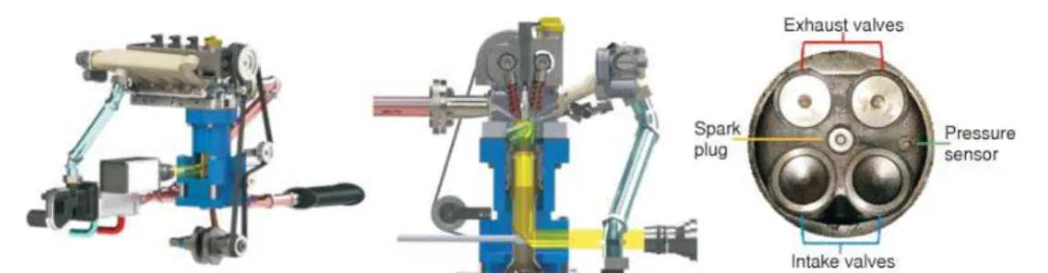
Measurements were performed on an optically accessible single cylinder engine (tab. 1). It is equipped with the cylinder head of a commercial power unit with a centrally located spark plug and side mounted six hole wall-guided injector. For this study, a surface discharge spark plug was used (fig. 1). In-cylinder pressure was measured with an accuracy of±0.5% using a quartz piezo-electric sensor flush-installed with the combustion chamber. Ambient pressure was around 1 atm and air temperature was in the 300-310 K range. Coolant and lubricant temper-ature was maintained between 320 and 340 K using an external conditioning unit.
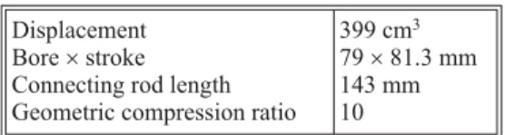
Table 1. Engine specifications Displacement
Bore´stroke Connecting rod length Geometric compression ratio
All trials were performed with commercial gasoline (95 octane number) at 2000 rpm and wide open throttle, fixing the injection pressure at 100 bar. Fuel delivery was performed as single injection (reference case strategy) and divided into two separate events (split injection), with equal values of opening time for the solenoid driven metering valve. The first injection oc-curred at 300 crank angle degrees (CAD) before top dead center (bTDC) for all conditions, whereas second injection timing was changed in the range of 140-150 CAD bTDC. Relative air-fuel ratiolwas maintained around 1.15 and was monitored with an accuracy of±1% using a wide band O2sensor fitted at the exhaust.
The CO and unburned HC exhaust gas concentrations were determined by a NDIR gas analyzer. For the analysis of NOxemissions, an electrochemical analyzer was used. Accuracy was around±3% with a reading resolution of 0.01% for the first component and 1 ppm for the other two species.
Optical set-up
The optical access to the combustion chamber was ensured by a fused-silica window (circular shape of diameter 68.5 mm and 18 mm of thickness) fitted onto an elongated hollow Bowditch piston. Self-lubricating teflon-bronze composite piston rings were used instead of a conventional lubrication system in the optical section, because of oil leakage and a consequent fouling of the quartz window.
The radiative emission induced by the combustion passed through the quartz window, then it was reflected by a 45° inclined elliptical mirror (50´75 mm) located inside the cavity of the piston and finally the emission was collected by the optical acquisition system (fig. 1). This was constituted by a UV-Nikon (78 mm focal length) objective coupled with an intensified CCD camera (matrix size of 1024´1024 pixels with a pixel size of 13´13mm, 16-bit pixel digitali-zation, and 1 MHz frequency). Optical methods based on chemiluminescence were used in the wavelengths range from ultraviolet (UV) to visible (VIS) to follow flame growth from the SI up to the opening of exhaust valves, with particular interest in the early stage of combustion pro-cess. Sequential and repetitive gating modes were used for the ICCD camera, allowing one frame per cycle detection rate with fixed gate width and with variable (sequential) and fixed (re-petitive) delay with respect to the trigger that corresponded to falling edge of the ignition coil charge signal. Optical data were recorded for 100 consecutive cycles, at a step of 1 CAD (83ms), with an exposure time of 42ms.
Image processing
In order to obtain quantitative information from the combustion visualization, macro-scopic parameters related to flame morphology were evaluated through image processing
oped in 2011 NI Vision [19]. ICCD detected flame emission sequences, as a first step, a circular mask was applied to select a region of interest corresponding to the combustion chamber area and to cut stray light and spurious signals from reflections at the boundaries of the piston crown. Then, images were converted in 8-bit (0-255) grey-level by extracting the intensity plane and look-up table transformations were employed to reach the best balance between contrast and brightness. In particular, after the application of a logarithmic function on pixel intensity, brightness was fixed at 136, contrast at 50.6, and the gamma value at 1.22. At this step of the procedure, thresholding was performed to obtain binarized images. In particular, a manual threshold type was used fixing 39 (on 0-255 scale) as the minimum intensity value. This proce-dure segmented the image in two regions, particle area and background, respectively, associat-ing intensity equal to 0 for all those pixels with an intensity lower than the threshold and 1 for the rest. In order to fill holes and remove small border objects, morphological transformation func-tions were applied.
Image processing allowed to evaluate the flame area for each binarized image by sum-ming up the pixels of the projected in-cylinder enflamed area. Moreover, it was possible to eval-uate the Waddel disk diameter,i. e.diameter of a disk with the same particle area, and the Hey-wood circularity factor. The latter parameter was calculated as the flame front perimeter divided by the circumference of a circle with the same area. The closer the particle shape is to a disk, the closer the Heywood circularity factor is to 1. Flame motion was studied through the position of the images' centroid that corresponded to (x, y) co-ordinates of the geometric center of each binarized flame image. Flame front propagation was followed up to the optical limit correspond-ing to~86.7% of the cylinder bore.
Thermodynamic analysis
Net indicated mean effective pressure (IMEP), its coefficient of variation (COV) and combustion related parameters were evaluated based on pressure data averaged over 200 con-secutive fired cycles, in order to minimize the influence of noise and cyclic variations. Given that only a brief investigation was intended, the simplified heat release approach was employed [20], ignoring heat transfer and blow-by losses:
dQ= p V V p
- +
-g
g 1 g
1 1
d d (1)
whereQ[J] is heat measured in,g– the ratio of specific heats,p[Pa] – the pressure,V [m3] – the
cylinder volume, and the working fluid considered as a mixture of ideal gases [21]. The specific heats ratio was calculated on the basis of approximation equations provided by NASA database [22], with bulk gas temperature calculated using the ideal gas law and assuming no changes in gas mass within the combustion chamber during the closed valves part of the cycle. Mass frac-tion burned (MFB) was calculated using the Rassweiler-Withrow [23] model,
MFB p V p V
p V p
n n n = -1 1 1 / / / ignition ignition EOC EOC ignition1/n Vignition
(2)
While the simplified approach does not provide a detailed analysis, the results can still be considered as valid for relative comparison between different injection strategies. This is fur-ther justified by the reduced influence of fluid properties, seen that only gasoline was used, as opposed to multi-fuel operation [24]. Also, given that the pressure traces feature comparable values, heat transfer and blow-by losses should influence in roughly the same way the calculated heat release and MFB for different injection strategies.
Results and discussion
Performance and combustion parameters
Previous numerical and experimental investigations demonstrated that the optimal single injection strategy for the selected DISI engine was realized by fixing the start of injection (SOI) at 300 CAD bTDC [25]. Further, preliminary studies about split injection fixing the first injection at 300 CAD bTDC and changing the second start of injection (SOI2) up to 90 CAD bTDC showed that the strategies with more delayed SOI2 featured numerous slow burn cycles and even misfires, most likely due to the fact that the fuel was not properly vaporized before ig-nition. For these reasons, the present work was focused on the analysis of optimal SOI2 in lean mixture conditions (1.15 air-fuel ratio) in the range 140-150 CAD bTDC.
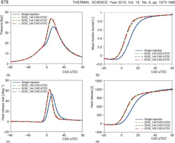
Figures 2-4 show the effects of SOI2 on engine performance and stability. Even if the gain in IMEP at maximum brake torque by employing split injection was below 4% fig. 2(a), the positive effect on combustion stability (evaluated through the coefficient of variation, COV) re-sulted significant fig. 2(b). It should be noted that the presented data refer to the average of 200 consecutive fired cycles.
In order to detail the effect of fuel injection strategy on the combustion process, spark timing was fixed at 20 CAD bTDC, a value that ensured comparable IMEP values for all the se-lected operative conditions. A more detailed analysis of pressure traces, related heat release and MFB values, fig. 3(a-d), revealed that modifications in combustion phasing were the reason for the observed changes in engine performance when employing split injection. It should be noted that negative MFB values in the first phases of combustion are due the simplifications associ-ated with the application of the Rassweiler-Withrow [23] model. Also, when comparing these results with optical data, the ratio of burned-unburned gas density should be considered;
theless, a good correlation between volume fraction burned and flame area was observed [26]. Single injection resulted in lower heat release values and it also featured delayed start of self-sustaining flame. All split injections sped up the initial phase of combustion with almost identical development among them. The peak pressure of single injection was strongly delayed. One possible reason for slower flame development and earlier and accelerated combustion for the alternative control strategy is that the split injection operated in more homogenous fuel-air mixture (most likely due to less wall impingement [27]).
As shown in fig. 4(a), split fuel delivery allowed to achieve higher combustion pres-sure compared to single injection, with a slight increase in the peak value when advancing SOI2. The coefficient of variation of the maximum pressure plotted in fig. 4(b) demonstrated higher repeatability of the combustion phenomena occurring inside the cylinder switching from single to split injection with SOI2_150 CAD bTDC as the most suitable injection strategy.
In agreement with previous results, the initial phase of combustion fig. 4(c) was shorter for double injection although the difference between those cases is within the resolution of the crank angle encoder. A more consistent difference was observed for the main combustion phase fig. 4(d) showing for the SOI2 at 150 CAD bTDC case the shortest period of bulk charge burning, while combustion duration increased as the second injection timing was delayed to-wards the top dead centre (TDC).
Optical analysis
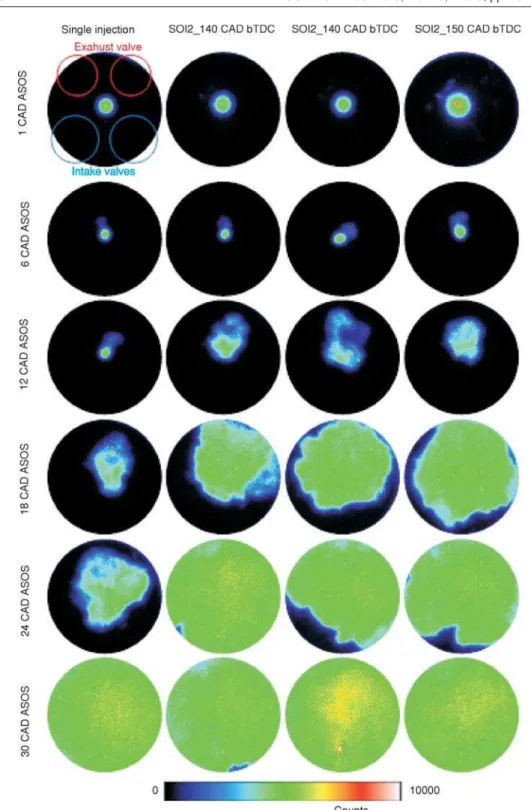
Following the results obtained through thermodynamic analysis of in-cylinder pres-sure traces, optical investigations were carried out to provide a more complete understanding of split injection effects on the combustion process. The sequential crank angle-resolved UV-visi-ble flame emission recorded during combustion (fig. 5), (with the abbreviation ASOS referring to after start of spark) showed that for all fuel injection strategies the flame front initiated in the spark plug region and evolved roughly in the same way until reaching the optical limit. The first CAD after ignition were characterized by high brightness induced by the plasma formed be-tween the spark plug electrodes [28]. The flame kernel was evident at around 4 CAD ASOS and at 6 CAD ASOS it was well resolved. The shape of burned and reacting gas volume did not show significant differences in the early stage of combustion until 10 CAD ASOS. From 12 CAD ASOS faster flame development was observed switching from single to split injection. A pre-ferred direction towards the exhaust valves was noticed for all conditions. The flame evolved with different velocity towards the intake and exhaust valves due to local gradients of tempera-ture and of air-fuel ratio, and to fluid motion (such as tumble). At a fixed CAD ASOS, the flame area was larger for the split injection conditions as shown in fig. 5. This indicates that injection splitting determined an increase in flame speed.
Figure 5. Selection of UV-visible flame emission images
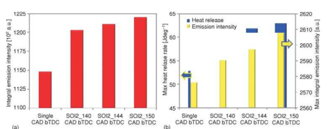
Regarding flame luminosity, it resulted comparable for all the conditions. On the other hand, the integral value (calculated by summing the emission intensity of each pixel within the combustion chamber for the entire combustion process), was higher for split injection. Further-more, as shown in fig. 6(a), integral luminosity increased at advancing SOI2. Since the luminos-ity in the UV-visible wavelength range was related to the radiative emissions of exothermal re-actions that occurred in the combustion chamber, the integral luminosity and heat release rate resulted correlated in terms of highest value fig. 6(b) and crank angle evolution (fig. 7). In par-Figure 6. Integral luminosity measured in the combustion chamber evaluated during the entire combustion process (a) and comparison between maximum integral luminosity and peak of heat release rate (b)
ticular, the optical data trend was similar to the rising part of the heat release rate curve, follow-ing exactly much of the combustion process. The emission intensity trends differed only in the late combustion stage.
It should be noted, that, in agreement with thermodynamic data, split injection determined a lower cyclic variation of flame emission and as a consequence of the combustion process, in particular in the early stages. Figure 8 shows the coefficient of variation related to the integral optical signal detected at 15 CAD ASOS on 150 consecutive engine cycles for all the settings.
The COVoptwas evaluated by the ratio between the standard deviation and the mean value of integral luminosity.
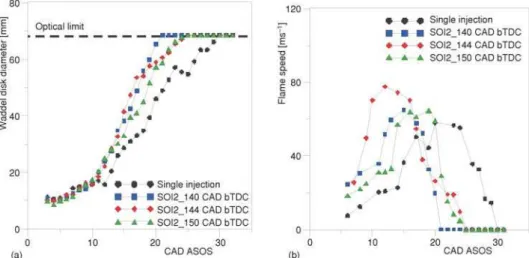
Application of image processing allowed to fol-low the flame evolution trough the Waddel disk di-ameter fig. 9(a) and related rate fig. 9(b) that corre-sponded to an equivalent flame speed. Split injection featured higher values for both these pa-rameters in the first phase of combustion up to the optical limit around 20 CAD ASOS. The SOI2 144 resulted faster in the early combustion stage (until 15 CAD ASOS) in agreement with the thermody-namic data (10% MFB). Image processing also al-lowed to evaluate the effect of fuel injection on flame shape through the Heywood factor (HF) (fig. 10).
Figure 8. Coefficient of variation of integral luminosity measured in the combustion chamber at 15 CAD ASOS for all the settings
Figure 9. Evolution of Waddel disk diameter (a) and flame speed (b)
Obviously, a circular shape was recorded after the flame reached the optical limit (i. e. HF equals unity). Split injection induced less distorted flame front more evident in the ap-proaching to the combustion chamber walls. This was a further confirmation of better air-fuel mixing realized by the split injection that reduced the amount of fuel deposits on piston surface and in particular in the intake valves region near the injector. These deposits formed fuel rich zones that slowed down the flame front propagation and distorted it [29]. As a consequence, a different flame path was evaluated trough the luminous center evolution. Figure 11 shows (x , y) of centroid co-ordinates from the spark timing until the flame reached the optical limit. As previ-ously observed, in the early stage of combustion the flame moved preferably towards the ex-haust valves with comparable behaviour for the selected conditions. Then a clockwise flow trend for both single and split injection strategies was observed. The path resulted slightly wider for split injection condition, suggesting that flame front progression was dominated by the cou-pling between the in-cylinder flow and the fuel concentration field.
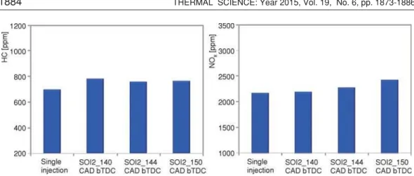
Concerning the pollutant emissions at the exhaust, the variation of CO and CO2 switching from single to split injection resulted comparable with the measurement uncertainty. On the other hand, as shown in fig. 12, a slight increase in unburned HC and NOx concentra-tion at the undiluted exhaust was measured. The results related to the smoke were more signifi-cant. The split injection allowed to reduce the exhaust opacity up to 20% with respect to single injection, as reported in fig. 13.
Specifically, the improvement of air-fuel mixing decreased the number and area of fuel rich zones due to fuel deposition in the combus-tion chamber. This decrease induced a reduc-tion in soot amount at the exhaust thanks to the reduction of diffusive flames due to the fuel deposits burning [29]. The effect can be well appre-ciated in fig.14 by comparing the flame images detected in the late combustion phase (80 CAD ASOS) in all the selected engine conditions.
Figure 12. The HC and NOxemissions at the exhaust for single and split injection
Figure 13. Opacity measured at the exhaust for single and split injection
Figure 14. Flame emission detected in the late combustion phase (80 CAD ASOS)
Conclusions
The paper presented results from detailed thermodynamic and optical analysis of dou-ble injection in comparison to single injection strategy in a DISI engine fuelled with commercial gasoline in lean burn conditions. Crank angle resolved in-cylinder pressure and UV-visible flame chemiluminescence images were post-processed to derive heat release rate, mass fraction burned, IMEP, circularity factor, and emission intensity for each test case. The split injection strategy showed better repeatability of combustion processes and more stable work output of the engine cycle. Moreover, combustion was overall faster, with a more rapid flame-development stage and quicker propagation during the main phase. The differences between the multiple in-jection cases were low. Nonetheless, there is a tendency indicating that earlier SOI2 leads to more favourable engine parameters values. Furthermore, the single injection strategy is charac-terized by higher flame wrinkling and slower flame growth in comparison to double injection. Interestingly all setups showed an overall tendency for flame centroid motion primarily towards the exhaust side of the combustion chamber first before expanding onto a central position, with a clockwise direction. Concerning the exhaust gas analysis, the double injection strategy shows a slight increase in HC, NOxemissions and significant reduction of smoke and soot production due to better fuel-air mixing and higher combustion efficiency.
References
[1] Alagumalai, A., Internal Combustion Engines: Progress and Prospects,Renew. Sust. Energ. Rev., 38
(2014), Oct., pp. 561-571
[2] Zhao, F.,et al., Automotive Spark-Ignited Direct-Injection Gasoline Engines,Progress in Energy and Combustion Science, 25(1999), 5, pp. 437-562
[3] Baumgarten, H.,et al., Vehicle Application of a 4-Cylinder Characteristics in a Spray-Guided DISI En-gine, SAE technical paper 2001-01-0735, 2011
[4] Oh, H.,et al., Effect of the Multiple Injection on Stratified Combustion Characteristics in a Spray-Guided DISI Engine, SAE technical paper 2011-24-0059, 2011
[5] Seo, J.,et al., Numerical Investigation of the Combustion Characteristics and Wall Impingement with De-pendence On Split-Injection Strategies from a Gasoline Direct-Injection Spark Ignition Engine, Proceed-ings of the Institution of Mechanical Engineers,part D: Journal of Automobile Engineering, 227(2013), 11, pp. 1518-1535
[6] Piock, W.,et al., Strategies Towards Meeting Future Particulate Matter Emission Requirements in Homo-geneous Gasoline Direct Injection Engines,SAE Int. J. Engines, 4(2011), 1, pp. 1455-1468
[7] Etheridge, J.,et al., Modelling Soot Formation in a DISI Engine,Proceedings of the Combustion Institute, 33(2011), 2, pp. 3159-3167
[8] Bonatesta, F.,et al., Part-Load Particulate Matter from a GDI Engine and the Connection with Combustion Characteristics,Applied Energy, 124(2014), Jul., pp. 366-376
[9] Qi, J., Q., Reitz, R. D., Modeling Soot Emissions from Wall Films in a Direct-Injection Spark-Ignition En-gine, on livetirst,International Journal of Engine Research(2014), doi: 10.1177/1468087414562008 [10] Drake, M. C., Haworth, D. C., Advanced Gasoline Engine Development using Optical Diagnostic and
Nu-merical Modeling,Proceedings of the Combustion Institute, 31(2007), 1, pp. 99-124
[11] Soid, S., Zainal, Z. A., Spray and Combustion Characterization for Internal Combustion Engines using Optical Measuring Techniques – a Review,Energy, 36(2011), 2, pp. 724-741
[12] Sick, V., 10- Optical Diagnostics for Direct Injection Gasoline Engine Research and Development, in:
Ad-vanced Direct Injection Combustion Engine Technologies and Development (Ed. H. Zhao), ISBN:
978-1-84569-389-3, 2010, pp. 260-286
[13] Dahlander, P., Hemdal, S., High-Speed Photography of Stratified Combustion in an Optical GDI Engine for Different Triple Injection Strategies, SAE technical paper 2015-01-0745, 2015
[14] Li, T.,et al., An Insight Into Effect of Split Injection on Mixture Formation and Combustion of DI Gaso-line Engines, SAE technical paper 2004-01-1949, 2004
[16] Fan, Q.,et al., Effect of the Fuel Injection Strategy on First-Cycle Firing and Combustion Characteristics during Cold Start in a TSDI Gasoline Engine,International Journal of Automotive Technology, 13(2012), 4, pp. 523-531
[17] Wislocki, K.,et al., Thermodynamic Aspects of Combustion in Gasoline Engines Fitted with a Multiple Fuel Injection,Journal of KONES, 18(2011), 4, pp. 543-553
[18] Serras-Pereira, J.,et al., An Analysis of the Combustion Behavior of Ethanol, Butanol, Iso-Octane, Gaso-line, and Methane in a Direct-Injection Spark-Ignition Research Engine.,Combustion Science and Tech-nology, 185(2013), 3, pp. 484-513
[19] Parker, J. R., Algorithms for Image Processing and Computer Vision, John Wiley and Sons, New York, USA, 2010
[20] Heywood, J. B., Internal Combustion Engine Fundamentals, McGraw-Hill, New York, USA, 1988 [21] Irimescu, A., Comparison of Combustion Characteristics and Heat Loss for Gasoline and Methane Fueling
of a Spark Ignition Engine,Proc Rom Acad Ser A, 14(2013), 2, pp. 161-168
[22] McBride, B. J., Gordon, S. I., Analysis, in Computer Program for Calculation of Complex Chemical Equi-librium Compositions and Applications, vol. 1311 NASA Reference Publication, NASA Lewis Research Center, NASA, Cleveland, O., USA,1994
[23] Rassweiler, G., Withrow, L., Motion Pictures of Engine Flames Correlated with Pressure Cards, SAE technical paper 380139, 1938
[24] Irimescu, A., Working Fluid Properties Variation during Combustion in Premixed Charge Hydrogen En-gines, SAE technical paper 2012-01-1646, 2012
[25] Costa, M.,et al., Study of Mixture Formation and Early Flame Development in a Research GDI (Gasoline Direct Injection) Engine through Numerical Simulation and UV-Digital Imaging., Energy, 77(2014), Dec., pp. 88-96
[26] Irimescu, A.,et al., Evaluation of Different Methods for Combined Thermodynamic and Optical Analysis of Combustion in Spark Ignition Engines, Energy Conversion and Management, 87(2014), Nov., pp. 914-927
[27] Serras-Pereira, J.,et al., Imaging and Heat Flux Measurements of Wall Impinging Sprays of Hydrocarbons and Alcohols in a Direct-Injection Spark-Ignition Engine,Fuel, 91(2012), 1, pp. 264-297
[28] Merola, S. S.,et al., UV-Visible Optical Characterization of the Early Combustion Stage in a DISI Engine Fuelled with Butanol-Gasoline Blend, SAE technical paper 2013-01-2638, 2013
[29] Merola, S. S.,et al., Effect of the Fuel Injection Strategy on the Combustion Process in a PFI Boosted Spark-Ignition Engine,Energy, 35(2010), 2, pp. 1094-1100