E
NERGY AND
E
NVIRONMENT
Volume 3, Issue 2, 2012 pp.305-322
Journal homepage: www.IJEE.IEEFoundation.org
Endoreversible Meletis-Georgiou cycle
Chang Liu, Lingen Chen, Fengrui Sun
College of Naval Architecture and Power, Naval University of Engineering, Wuhan 430033, P. R. China.
Abstract
An endoreversible Meletis-Georgiou (MG) cycle model with constant specific heat of working fluid is established and the analytical formulae of performance parameters including working fluid temperatures, work output and efficiency are derived using the finite time thermodynamic theory. The performance of the endoreversible MG cycle is analyzed and optimized. The characteristics of the work output versus compression ratio, efficiency versus compression ratio, and work output versus efficiency are obtained, respectively, by detailed numerical examples, and the effects of changeover ratio, over-expansion ratio, heating value of fuel, heat transfer loss coefficient, initial temperature of working fluid, and the transferred volume ratio on the relationship mentioned above are also discussed. The maximum work output and the corresponding optimal compression ratio, changeover ratio, over-expansion ratio as well as the maximum efficiency and the corresponding optimal changeover ratio and over-expansion ratio are obtained by taking the cycle work output and efficiency as the optimization objectives, respectively. Moreover, the effects of the parameters such as the heating value of fuel, heat transfer loss coefficient, initial temperature of working fluid, and the transferred volume ratio on the maximum work output, the maximum efficiency and the corresponding optimal ratios are analyzed. The results may provide guidelines for the optimal design of practical MG engine.
Copyright © 2012 International Energy and Environment Foundation - All rights reserved.
Keywords: Finite time thermodynamics; Meletis-Georgiou cycle; Performance analysis and optimization.
1. Introduction
under the condition of variable temperature heat sources. Hou [31] compared the difference of performance between Otto and Atkinson cycle considering the heat transfer loss. Al-Hinti et al. [32] studied the performance of Diesel cycle considering the new heat transfer loss model.
Vane Rotary engine concepts are nearly as old as the reciprocating engine. Although the former hasn’t evolved into a widespread commercial application, new inventions are patent regularly [33-36] in recent years. The representative one is Meletis-Geogiou vane rotary invented by Meletis and Geogiou, which awarded a patent [34] in 1998. Vane rotary concept was applied in the Meletis-Geogiou (MG) engine, which exhibits two advantages against the conventional reciprocating engines. Firstly, a larger number of thermodynamic cycles implemented per shaft rotation in vane rotary engine. Secondly, the configuration of the engine is radial symmetry, which leads to radial force balance and runs smoothly. Recently, Geogiou et al. [37] performed a classical thermodynamic analysis for the ideal MG cycle without considering any irreversibility in the cycle. Based on it, this paper will establish a model of endoreversible MG cycle with consideration of the heat transfer loss using finite-time thermodynamic theory [1-20], and analyze and optimize the performance of the endoreversible cycle.
2. Cycle model
Figure 1 shows a two-lobe rotor MG vane rotary engine [37]. It consists of two parts: a circular stator and a rotor. Various chambers such as the inlet chamber VIN, the compression one VC, the expansion one
E
V , and the exhaust one VEX are formed when the engine runs. These chambers are produced by the rotor outer surface, the stator inner surface, the diaphragms moving radially and the two end plates.
Figure 1a shows two chambers with VT. They are the maximum volume created by the stator and the rotor. When the rotor rotates, the diaphragms are inserted into the cavity, so that their tips are in contact with the rotor surface. The entrance of the diaphragms separates two chambers into four new chambers which are shown in Figure 1b. An additional chamber is fixed on the stator, called combustion chamber
CC
V . On the each side of the combustion chamber is a diaphragm. At any moment only one of the two is entered and keeps contact with the rotor. These diaphragms divide the left chamber VT into the compression chamber VC and the expansion chamber VE. The diaphragm 3 separates the right chamber
T
V into the inlet chamber VIN and the exhaust chamber VEX, each of the two communicates with the atmosphere through a port. Initially, the combustion chamber is connected to the expansion one, filling it with high-pressure working fluid. At this stage diaphragm 1 entered inside, while diaphragm 2 remains inside the stator and separate from the rotor. On the left of diaphragm 1 is the compression chamber VC, which compressed the air as the rotor turns. At a certain angular position shown in Figure 1c, diaphragm 1 is lifted, while diaphragm 2 is entered inside the cavity and contacts the rotor surface. The changeover makes combustion chamber VCC and the section of the expansion volume between diaphragm 1 and 2 (∆V ) become part of the compression volume. The rest working fluid in the expansion chamber continues to expand until the rotor tip uncovers the exhaust port. At this point, the expansion chamber VE becomes the exhaust chamber VEX. The process mentioned above takes place rotationally in the device. The working process of MG engine is described below:
(1) Initially, the rotor lobe covers the port leading to the combustion chamber. Constant volume heating takes place.
(2) As the rotor turns, the combustion chamber discharges high-pressure working fluid into the expansion one, doing work on the rotor. The starting volume of expansion chamber is VE =VCC =V5 =V4. The volume of working fluid at state i is Vi. At the same time, compression process is implemented inside the compression chamber as soon as the rotor covered the inlet port. The exhaust process starts in the chamber on the right side.
Figure 1. Cross section of MG engine [37]
T−s and P V− diagrams for the MG cycle are shown in Figures 2 and 3. Process 1→2 is an isentropic compression. In process 2→3, the working fluid at state 2 is mixed with part of the expanding working fluid at state 6 due to the changeover of diaphragms 1 and 2. Process 3→4 is an isentropic compression. Process 4→5 is an isochoric heating. Process 5→6 is an isentropic expansion. Process 6→7
corresponds to the changeover process, as a result, volume and mole number are reduced, and the temperature, the pressure, and the entropy of the working fluid remain the same. Process 7→8 is an isentropic expansion. The heat rejections are an isochoric process8→9 and an isobaric process9→1. Since the finite size of the ports, part of the VT can not be employed in the compression- expansion processes. A parameter κ=V9/VT is defined as the maximum exploitable section of VT. The other parameters rE =V9/V1, over-expansion ratio and λ= ∆V V/ T, transferred volume ratio, are also defined. So the following volume restrictions are [37]:
9 T E 1 8
V =κV =r V =V (1)
6 7 3 2 CC 4 T
V −V =V −V =V + ∆ =V V +λV (2)
6 T 4 2
V =V +V −V (3)
5 4
V =V (4)
The ratios r=V V1/ 4 and rC=V V1/ 2 are compression and changeover ratios. The volumes at the corresponding cycle state points are:
2 (1 / C) 1
V = r ⋅V (5)
3 [ ( E/ ) 1 / 1 / C] 1
V = λ r κ + r+ r ⋅V (6)
4 5 (1 / ) 1
V =V = r V⋅ (7)
6 (E / 1 / 1 / C) 1
V = r κ+ r− r V (8)
(
)
7 {[ 1 E / ] 1 / C} 1
8 9 E 1
V =V = ⋅r V (10)
The volume transfer in the processes 2→3 and 6→7 make the mole number of the working fluid during the processes 3→ → →4 5 6 is larger than that during the processes 7→ → → →8 9 1 2. The relations are obtained based on the law of mass conservation:
1 2 7 8 9
M =M =M =M =M (11)
3 4 5 6
M =M =M =M (12)
Since the temperature and the pressure of working fluid remained same during process 6→7, the mole number ratio is:
3/ 2 6/ 7 6/ 7
M M =M M =V V (13)
For the isentropic compression process 1→2, one has:
1 1
2 ( 1/ 2) 1 C 1
T = V V γ−T =rγ−T (14)
The parameter γ is the ratio of specific heats. In process 2→3, the working fluid at state 2 is mixed with the part of the expanding working fluid at state 6 due to the changeover of diaphragms 1 and 2. Hence, the compression volume changes from 2 to 3, while the expansion one is reduced from 6 to 7. As a result of the mixing, the temperature, the pressure, the volume, and the mole number of working fluid change during the process 2→3. According to the law of energy conservation and the perfect gas assumption, one has:
3 3 2 2 6( 3 2)
vm vm vm
C T M =C T M +C T M −M (15)
The parameter Cvm is the specific heat with constant volume. So, T3 can be written as:
3 ( 2/ 3) 2 [1 ( 2/ 3)] 6
T = M M T + − M M T (16)
For the isentropic compression process 3→4, one has,
1 1
4 ( 3/ 4) 3 [( E / ) 1 / C] 3
T = V V γ−T = λr r κ + +r r γ−T (17)
For an ideal-cycle model, there are no irreversible losses [37]. However, for a real cycle, the heat-transfer irreversibility between the working fluid and the engine wall is not negligible. One can assume that the heat loss through the engine wall is proportional to the average temperature of both working fluid and the engine wall and the wall temperature is constant. The heat added to the working fluid by combustion is given in the following linear relation [21]:
3{ [( 4 5) / 2 0]} 3[ ( 4 5)]
in
Q =M A′−B T′ +T −T =M A−B T +T (18)
where A′ is the heating value of the fuel, B′is the heat leakage coefficient of the wall, T0 is the ambient temperature, and A=A′+B T′ 0 and B=B′/ 2 are two constants related to the combustion heating value of the fuel and heat transfer loss of the wall. The heat added to the working fluid by combustion can also be given as:
3 ( 5 4)
in vm
5
T can be obtain from equations (18) and (19):
5 [ ( vm ) ] / (4 vm )
T = A+ C −B T C +B (20)
For the isentropic expansion 5→6, one has,
1 1
6 ( 5/ 6) 5 [( C) / (E C C)] 5
T = V V γ−T = κr r r r−κr+κr γ−T (21)
Figure 2. T−s diagram for MG cycle model [37]
Figure 3. P V− diagram for MG cycle model [37]
3. Work output and thermal efficiency
Temperatures T3, T4, T5 and T6 at each state point can be obtained from equations (16), (17), (20) and (21):
(
)(
)
(
)
[
]
(
) (
)(
)
[
]
1 1
2 3 1 7 6
3 1
7 6
/ 1 / / ( )
1 / ( ) / ( )
vm C C E C C
vm vm E C C E C C
C B M M r T A M M r r r r r r T
C B C B M M r r r r r r r r r r
γ γ
γ
κ κ κ
λ κ κ κ κ
− −
−
+ + − − +
=
+ − − − + + − + (22)
[
]
(
) (
)(
)
[
]
1
2 3 1
1 7 6
4 1
7 6
( )( / )( / ) (1
/ ) ( ) / ( )
1 / ( ) / ( )
vm E C C
E C C E C C
vm vm E C C E C C
C B M M r r r r r T A
M M r r r r r r r r r r
T
C B C B M M r r r r r r r r r r
γ
γ
γ λ κ
λ κ κ κ κ
λ κ κ κ κ
− − − + + + + − + + − + =
(
)
[
]
1
2 3 1
5 1
7 6
( / )( / ) / ( )
( ) / ( ) 1 / ( ) / ( )
E C C vm
vm vm E C C E C C
M M r r r r r T A C B
T
C B C B M M r r r r r r r r r r
γ
γ λ κ
λ κ κ κ κ
−
−
+ + + −
=
+ − − − + + − + (24)
(
)
(
)(
)
1
2 3 1
6 1 1
7 6
/ ( / ) / ( )
( ) / ( ) / / 1 1 / / 1 /
E C C vm
vm vm E C E C
M M r r r r r T A C B
T
C B C B r r r r M M r r r r
γ
γ γ
λ κ
κ λ κ
−
− −
+ + + −
=
+ − − + − − + + (25)
For process 6→7, the volume and the mole number of the working fluid are reduced since the separation, meanwhile, the temperature, the pressure, and the entropy remain the same:
7 6
T =T (26)
For the isentropic expansion process 7→8, one has
[
]
{
[
]
}
(
)
{
[
]
}
1 1
8 7 8 7 7
1
2 3 1
1
1 7 6
( / ) [(1 ) / 1 / ( )]
( / )( / ) / ( )
( ) / ( ) ( ) / (1 )
1 / ( ) / (1 )
E C
E C C vm
vm vm E C C E E C
E C C E E C
T V V T r r T
M M r r r r r T A C B C B C B r rr r r r r r
M M r r r r r r r r
γ γ γ γ γ λ κ λ κ
κ κ λ κ
λ κ κ λ κ
− − − − − = = − − + + + − = + − − + − − − − + + − − (27)
For the isochoric heat rejection process 8→9, the pressure of the working fluid is reduced to the atmospheric pressure, one has
9 ( 9/ 8) 8 ( 8 1 9) / 1 1 E 1
T = P P T = V T P V P =r T (28)
The work produced in the cycle includes
56 3 vm( 5 6)
W =M C T −T (29)
78 1 vm( 7 8)
W =M C T −T (30)
The work consumed in the cycle includes
12 1 vm( 2 1)
W =M C T −T (31)
34 3 vm( 4 3)
W =M C T −T (32)
91 9( 1 9) 1 vm 1( 1)(E 1)
W =P V −V =M C T γ− r − (33)
Thus, the net work output of the endreversible MG cycle is
56 78 12 34 91
1 1
3 1 3 1
1
1 3 1 1 3
1
3
{ [ / ( )] ( ) (1 / ) }{[( /
) ( / ) / ( )] / {( ) / ( ) (1 / )
[( ) / ( )] }} [1 ( / 1
/
vm C E C C E E C
C vm vm vm
E C C E C C vm E
W W W W W W
C M r r r r r r M M M r r r r r
r r M M T A C B C B C B M M
r r r r r r r r r r C M r r
r r
γ γ
γ
γ
κ κ κ λ κ
κ λ κ κ κ λ κ
− − − − = + − − − = + − + − − + + + − + − − − × + + − + + − +
+ 1 1
1 3 1 1 3
1
1 3
1 1
1 1
) ]{{( )( / ) (1 / )[ / (
)] } / {( ) ( )(1 / )[( ) / (
)] }} [( 1)( 1) ]
C vm C C E C
C vm vm E C C E C
C vm E C
C B M M r T A M M r r r r r
r C B C B M M r r r r r r r r
r r C M T r r
γ γ
γ
γ γ
κ κ
κ λ κ κ
κ κ γ
− − − − − + + − − + + − − − + + − + + − − − (34)
1 1
3 1 3 1
1
1 3 1 1 3
1 1
3
/
{ [ / ( )] ( ) (1 / ) }{[( /
) ( / ) / ( )] / {( ) / ( ) (1 / )[(
) / ( )] }} [1 ( / 1 / ) ]{{(
)
in
vm C E C C E E C
C vm vm vm E C
C E C C vm E C vm
W Q
C M r r r r r r M M M r r r r r r
r M M T A C B C B C B M M r r r
r r r r r r r C M r r r r C
B
γ γ
γ
γ γ
η
κ κ κ λ κ
λ
κ κ κ κ λ κ
− − − − − = + − + − − + + + − + − − − + + − + + − + + + = 1 1
1 3 1 1 3
1
1 3 1 1
1
1
3 2 3 1
( / ) (1 / )[ / ( )] } / {( )
( )(1 / )[( ) / ( )] }}
[( 1)( 1) ]
{ {[2 ( / )( / ) 2 / ( )] / {(
C C E C C vm
vm E C C E C C vm
E C
vm E C C vm vm vm
M M r T A M M r r r r r r C B
C B M M r r r r r r r r r r C M T
r r
M A B C M M r r r r r T C A C B C
γ γ
γ
γ
γ
κ κ κ
λ κ κ κ κ
γ λ κ − − − − − + − − + + − − − + + − + + × − − − − + + + − 1 7 6 )
( vm )(1 / )[( E C C ) / (E C C)] } / ( vm )}}
B C B M M λr r r κr κr r r r κr κr γ− A C B
+
− − − + + − + − −
(35)
According to the feasibility of the engine cycle, state point 9 lies between state points 8 and 1. The maximum over-expansion ratio is reached when T9 =T8. So substituting T9 =T8 into (28) yields T8 =r TE 1. Combining T8 =r TE 1 with Eqs. (26) and (27) gives:
1
6 1
[(1 ) / 1 / (r rE C)] T r TE
γ
λ κ −
− − = (36)
For the fixed r , T1 and the parameters κ, λ and rC, T2 can be derived from Eq. (14). Substituting T2 into Eq. (16) and combining Eqs.(17), (20), (21) with (36) yields the maximum over-expansion ratio
max
( )rE . The variation range of rE is:
min max
1=( )rE ≤rE ≤( )rE (37)
The heat rejection process is an isochoric one when rE =( )rE min =1. The heat rejection process is an isobaric one when rE =( )rE max. The relation between ( )rE max and r is shown in Figure 4 with the parameter set according to Ref. [37]. The range of ( )rE max is from 1.6 to 3 when the compression ratio varies from 2 to 20.
Figure 4. The maximum of over-expansion ratio versus compression ratio characteristic
4. Performance analyses
According to Ref. [37], the following parameters are used in the calculations: r=10, rC =2, rE =1.2,
0.15
λ = , κ =0.9, and T1=288K. The range of A is 95000∼105000 /J mol, the range of B is
20∼30 / (J mol K⋅ ), 5
1 1.57 10
M = × − kmol, Cvm=20.78 / (J mol K⋅ ), γ =1.4. In the regions of parameters
compression ratio, as well as the work output versus efficiency are obtained by detailed numerical examples, and the effects of the changeover ratio rC, the over-expansion ratio rE, the heating value A of fuel, heat transfer loss coefficient B, initial temperature of working fluid T1, and the transferred volume ratio λ on the performance of the endoreverisble MG cycle are discussed.
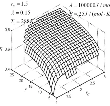
Figures 5-7 show the effect of changeover ratio rC on the cycle performance. One can see that for any given rC, the work output versus compression ratio characteristic is parabolic-like curve, the efficiency increases with the increase of compression ratio, and the work output versus efficiency characteristic is parabolic-like curve. For any given r, the work output versus changeover ratio and the efficiency versus changeover ratio characteristics are parabolic-like curves.
Figure 5. Influence of changeover ratio on work output versus compression ratio characteristic
Figure 7. Influence of changeover ratio on work output versus efficiency characteristic
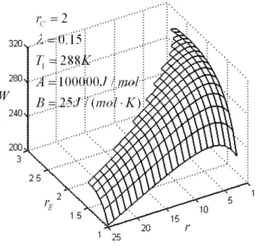
Figures 8-10 show the effect of over-expansion ratio rE on the cycle performance. One can see that the range of compression ratio decreases with the increase of rE. For any given rE, the work output versus compression ratio characteristic is a parabolic-like curve, the efficiency increases with the increase of compression ratio, and the work output versus efficiency characteristic is a parabolic-like curve. For any given r varies from 1 to 20, the work output versus expansion ratio and the efficiency versus over-expansion ratio characteristics are parabolic-like curves. For any given r varies from 20 to 25, the characteristics of work output versus compression ratio and the efficiency versus compression ratio are monotonic increasing functions since the range of over-expansion ratio rE decreases when compression
r
ratio increases.Figure 9. Influence of over-expansion ratio on efficiency versus compression ratio characteristic
Figure 10. Influence of over-expansion ratio on work output versus efficiency characteristic
increase of the transferred volume ratio λ, the range of compression ratio decreases, the efficiency increases, and the work output does not change obviously.
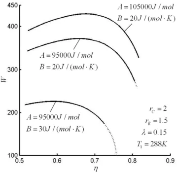
Figure 11. Influences of the heating value of fuel and heat transfer loss coefficient on the work output versus efficiency characteristic
Figure 12. Influences of initial temperature of working fluid and the transferred volume ratio on work output versus efficiency characteristic
5. Performance optimization
The maximum work output Wopt and the corresponding optimal compression ratio W opt
r , changeover ratio
,
W C opt
r , over-expansion ratio ,
W E opt
r as well as the maximum efficiency ηopt and the corresponding optimal changeover ratio rC opt,
η
and over-expansion ratio rE opt, η
as the heating value of fuel, heat transfer loss coefficient, initial temperature of working fluid, and the transferred volume ratio on the maximum work output, the maximum efficiency and the corresponding optimal ratios are analyzed by detailed examples.
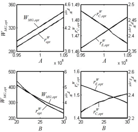
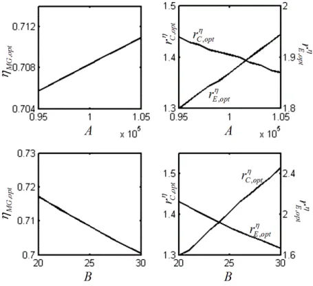
Figures 13 and 14 show the effects of the heating value (A) of fuel and heat transfer loss coefficient (B) on the maximum work output, the maximum efficiency and the corresponding optimal ratios. In Figures 13a, 13b, 14a and 14b, the parameters used are: λ=0.15, T1=288K and B=25 / (J mol K⋅ ). In Figure 13c, 13d, 14c and 14d, the parameters used are: λ=0.15, T1 =288K, A=100000 /J mol. One can see that
opt
W , ηopt, W opt
r , ,
W C opt
r , and rE opt, η
increase, and ,
W E opt
r and rC opt, η
decrease with the increase in A or the decrease in B.
Figures 15 and 16 show that the effects of initial temperature of working fluid and the transferred volume ratio λ on the cycle performance. In Figures 15a, 15b, 16a and 16b, the parameters used are: λ =0.15,
100000 /
A= J mol and B=25 / (J mol K⋅ ). In Figures 15c, 15d, 16c and 16d, the parameters used are:
1 288
T = K, A=100000 /J mol and B=25 / (J mol K⋅ ). One can see that Wopt, ηopt, W opt
r , ,
W E opt
r , and rE opt, η
decrease and W, C opt
r and rC optη, increase with the increase in T1. Wopt, ηopt, W, C opt
r , rC optη, , and W, E opt
r increase, and rE opt,
η
and W opt
r decrease with the increase in λ.
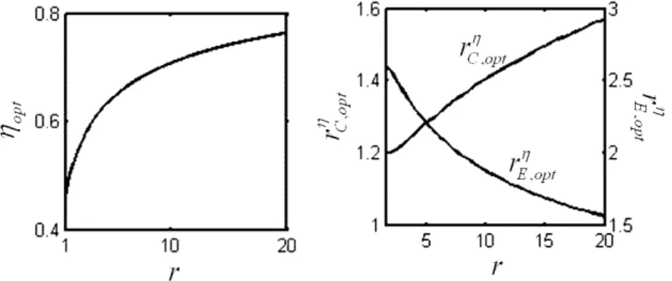
Figure 17 shows that the effect of compression ratio r on the cycle performance. The parameters used are: λ =0.15, T1=288K, A=100000 /J mol, and B=25 / (J mol K⋅ ). One can see that ηopt and rC opt,
η
increase, and rE opt, η
decrease with the increase in r.
Figure 14. Influence of the heating value of fuel and heat transfer loss coefficient on the maximum efficiency and the corresponding optimal changeover ratio, over-expansion ratio
Figure 15.Influence of initial temperature of working fluid and the transferred volume ratio on the maximum work output and the corresponding optimal compression ratio, changeover ratio,
Figure 16. Influence of initial temperature of working fluid and the transferred volume ratio on the maximum efficiency and the corresponding optimal changeover ratio, over-expansion ratio
Figure 17. Influence of compression ratio on the maximum efficiency and the corresponding optimal changeover ratio, over-expansion ratio
6. Conclusion
An endoreversible Meletis-Georgiou (MG) cycle model considering heat transfer loss is established and the analytical formulas of the work output and efficiency of the cycle are derived. The effects of the heating value of fuel, heat transfer loss coefficient, initial temperature of working fluid, the transferred volume ratio on the cycle performance are analyzed by detailed numerical examples. The maximum work output and the corresponding optimal compression ratio, changeover ratio, over-expansion ratio, as well as the maximum efficiency and the corresponding optimal changeover ratio and over-expansion ratio are obtained by taking the cycle work output and efficiency as the optimization objectives, respectively. Moreover, the effects of design parameters on the on the maximum work output, the maximum efficiency and the corresponding optimal ratios are analyzed. Based on the analyses, one can conclude:
parabolic-like curve. For any given compression ratio, the work output versus changeover ratio and the efficiency versus changeover ratio are parabolic-like curves.
(2) The range of compression ratio decreases with the increase of over-expansion rE. For any given rE, the work output versus compression ratio is a parabolic-like curve, the efficiency increases with the increase of compression ratio, the work output versus efficiency characteristic is a parabolic-like curve. For any given compression ratio, the work output versus over-expansion ratio and the efficiency versus over-expansion ratio characteristics are parabolic-like curves.
(3) With the increase of the heating value of fuel A or the decrease of heat transfer loss coefficient B, the range of compression ratio decreases, the maximum work output Wopt and the maximum efficiency
opt
η increase, the optimal compression ratio W opt
r and the optimal changeover ratio ,
W C opt
r corresponding to the maximum work output increase, the optimal over- expansion ratio ,
W E opt
r corresponding to the maximum work output decreases, the optimal changeover ratio rC opt,
η
corresponding to the maximum
efficiency decreases, the optimal over- expansion ratio rE opt, η
corresponding to the maximum efficiency increases.
(4) With the increase of the initial temperature T1, the range of compression ratio decreases, the maximum work output Wopt and the maximum efficiency ηopt decrease, the optimal compression ratio
W opt
r and the optimal over-expansion ratio W, C opt
r corresponding to the maximum work output decrease, the optimal changeover ratio ,
W C opt
r corresponding to the maximum work output decreases, the optimal changeover ratio rC optη, corresponding to the maximum efficiency increases, and the optimal over-expansion ratio rE opt,
η
corresponding to the maximum efficiency decreases.
(5) The influence of the transferred volume ratio λ on the work output and the efficiency is slight. With the increase of the transferred volume ratio λ, the range of compression ratio decreases, the maximum work output Wopt and the maximum efficiency ηopt increase, the optimal compression ratio
W opt
r
corresponding to the maximum work output decreases, the optimal changeover ratio ,
W C opt
r and the optimal over-expansion ratio ,
W E opt
r increase, the optimal changeover ratio rC opt,
η corresponding to the
maximum efficiency and the optimal over-expansion ratio rE opt, η
corresponding to the maximum efficiency decrease.
(6) With the increase of compression ratio r, the maximum efficiency ηopt and the corresponding optimal changeover ratio rC opt,
η
increase, and the optimal over-expansion ratio rE opt, η
corresponding to the maximum efficiency decreases.
The results mentioned above may provide some guidelines for the optimal design of practical MG engine.
Acknowledgements
This paper is supported by The National Natural Science Foundation of P. R. China (Project No. 10905093), The Program for New Century Excellent Talents in University of P. R. China (Project No. NCET-04-1006) and The Foundation for the Author of National Excellent Doctoral Dissertation of P. R. China (Project No. 200136).
References
[1] Andresen B, Berry R S, Ondrechen M J, Salamon P. Thermodynamics for processes in finite time. Acc. Chem. Res., 1984, 17(8): 266-271.
[2] Bejan A. Entropy generation on minimization: The new thermodynamics of finite-size device and finite-time processes. J. Appl. Phys., 1996, 79(3): 1191-1218.
[3] Feidt M. Thermodynamique et Optimisation Energetique des Systems et Procedes (2nd Ed.). Paris: Technique et Documentation, Lavoisier, 1996.
[4] Berry R S, Kazakov V A, Sieniutycz S, Szwast Z, Tsirlin A M. Thermodynamic Optimization of Finite Time Processes. Chichester: Wiley, 1999.
[6] Chen L, Sun F. Advances in Finite Time Thermodynamics: Analysis and optimization. New York: Nova Science Publishers, 2004.
[7] Chen L. Finite-Time Thermodynamic Analysis of Irreversible Processes and Cycles (in Chinese). Beijing: High Education Press, 2005.
[8] Muschik W, Hoffmann K H. Endoreversible thermodynamics: A tool for simulating and comparing processes of discrete systems. J. Non-Equilib. Thermody., 2006, 31(3): 293-317.
[9] Feidt M. Optimal use of energy systems and processes. Int. J. Exergy, 2008, 5(5/6): 500-531. [10] Sieniutycz S, Jezowski J. Energy Optimization in Process Systems. Oxford: Elsevier, 2009.
[11] Feidt M. Thermodynamics applied to reverse cycle machines, a review. Int. J. Refrigeration, 2010, 33(7): 1327-1342
[12] Feng H, Chen Li, Sun F. Finite time exergoeconomic performance optimization for an irreversible universal steady flow variable-temperature heat reservoir heat pump cycle model. Int. J. Energy and Environment (IJEE), 2010, 1(6): 969-986.
[13] Li J, Chen L, Sun F. Ecological performance of a generalized irreversible Carnot heat engine with complex heat transfer law. Int. J. Energy and Environment (IJEE), 2011, 2(1): 57-70.
[14] Kan X, Chen L, Sun F, Wu F. Finite time exergoeconomic performance optimization of a thermoacoustic heat engine. Int. J. Energy and Environment (IJEE), 2011, 2(1): 85-98.
[15] Li J, Chen L, Sun F. Finite-time exergoeconomic performance of an endoreversible Carnot heat engine with complex heat transfer law. Int. J. Energy and Environment (IJEE), 2011, 2(1): 171-178.
[16] Chen L, Yang B, Sun F. Exergoeconomic performance optimization of an endoreversible intercooled regenerated Brayton cogeneration plant. Part 1: thermodynamic model and parameter analyses. Int. J. Energy and Environment (IJEE), 2011, 2(2): 199-210.
[17] Yang B, Chen L, Sun F. Exergoeconomic performance optimization of an endoreversible intercooled regenerated Brayton cogeneration plant. Part 2: heat conductance allocation and pressure ratio optimization. Int. J. Energy and Environment (IJEE), 2011, 2(2): 211-218.
[18] Ding Z, Chen L, Sun F. Performance characteristic of energy selective electron (ESE) heat engine with filter heat conduction. Int. J. Energy and Environment (IJEE), 2011, 2(4): 627-640.
[19] Ma K, Chen L, Sun F. Optimization of a model external combustion engine for maximum work output with generalized radiative heat transfer law. Int. J. Energy and Environment (IJEE), 2011, 2(4): 723-738.
[20] Xia D, Chen L, Sun F. Endoreversible four-mass-reservoir chemical pump with diffusive mass transfer law. Int. J. Energy and Environment, 2011, 2(5): 909-920.
[21] Klein S A. An explanation for observed compression ratios in internal combustion engines. Trans ASME J. Eng Gas Turbine Pow., 1991, 113(4):511-513.
[22] Wu C, Blank D A. The effect combustion on a work—optimized endoreversible Otto cycle. J Energy Inst., 1992, 65(1):86-89.
[23] Blank D A, Wu C. Optimization of the endoreversible Otto cycle with respect to both power and mean effective pressure. Energy Convers. Manage., 1993, 34(12):1255-1209.
[24] Chen L, Wu C, Sun F. Heat transfer effects on the net work output and efficiency characteristics for an air standard Otto cycle. Energy Convers. Manage., 1998, 39(7): 643-648.
[25] Chen L, Zen F, Sun F, Wu C. Heat transfer effects on the net work output and power as function of efficiency for air standard Diesel cycle. Energy, Int. J., 1996, 21(12): 1201-1205.
[26] Lin J, Chen L, Wu C, Sun F. Finite-time thermodynamic performance of Dual cycle. Int. J. Energy Res., 1999, 23(9): 765-772.
[27] Hou S S. Heat transfer effects on the performance of an air standard Dual cycle. Energy Convers. Manage., 2004, 45(): 3003-3015.
[28] Sahin B, Kesgin U, Kodal A, Vardar N. Performance optimization of a new combined power cycle based on power density analysis of the Dual cycle. Energy Convers. Manage., 2002, 43(15): 2019-2031.
[29] Al-Sarkhi A, Akash A B, Jaber J O, Mohsen M S, Abu-Nada E. Efficiency of Miller engine at maximum power density. Int. Comm. Heat Mass Transfer, 2002, 29(8): 1159-1157.
[31] Hou S S. Comparison of performances of air standard Atkinson and Otto cycles with heat transfer considerations. Energy Convers. Manage., 2007, 48(5): 1683-1690.
[32] Al-Hinti I, Akash B, Abu-Nada E, Al-Sarkhi A. Performance analysis of air-standard Diesel cycle using an alternative irreversible heat transfer approach. Energy Convers. Manage., 2008, 49(11): 3301-3304.
[33] Penn J P. Radial Vane Rotary Engine. USA Patent Office, no 5,540,199, 30-07-1996.
[34] Meletis E, Georgiou D P. Vaned Rotary Engine with Regenerative Preheating. WPO, no 98/10172, 12-03-1998.
[35] Yamashina C, Miyakawa S. Vane Type Rotary Machine. European Patent Office, no 1113175, 03-09-1999.
[36] Akmandor I S, Ersoz N. Rotary Vane Engine and Thermodynamic Cycle. WPO, no 2004/022919, 18-03-2004.
[37] Georgiou D P, Theodoropoulos N G, Milidonis K F. Ideal thermodynamic cycle analysis for the Meletis-Georgiou vane rotary engine concept. J. Thermodyn, 2010(2010), Article ID 130692, DOI: 10.1155/2010/130690.
Chang Liu received his BS degree from the University of South China, P R China in 2009. He is
pursuing for his MS in power engineering and engineering thermophysics of Naval University of Engineering, P R China. His work covers topics in finite time thermodynamics and technology support for propulsion plants. He is the author of over 3 peer-refereed papers.
Lingen Chen received all his degrees (BS, 1983; MS, 1986, PhD, 1998) in power engineering and
engineering thermophysics from the Naval University of Engineering, P R China. His work covers a diversity of topics in engineering thermodynamics, constructal theory, turbomachinery, reliability engineering, and technology support for propulsion plants. He has been the Director of the Department of Nuclear Energy Science and Engineering, the Director of the Department of Power Engineering and the Superintendent of the Postgraduate School. Now, he is Dean of the College of Naval Architecture and Power, Naval University of Engineering, P R China. Professor Chen is the author or co-author of over 1200 peer-refereed articles (over 510 in English journals) and nine books (two in English).
E-mail address: [email protected]; [email protected], Fax: 83638709 Tel: 0086-27-83615046
Fengrui Sun received his BS degree in 1958 in Power Engineering from the Harbing University of
![Figure 1. Cross section of MG engine [37]](https://thumb-eu.123doks.com/thumbv2/123dok_br/16339099.188751/3.892.109.785.96.435/figure-cross-section-of-mg-engine.webp)
![Figure 3. P V − diagram for MG cycle model [37]](https://thumb-eu.123doks.com/thumbv2/123dok_br/16339099.188751/5.892.251.643.595.870/figure-p-v-diagram-for-mg-cycle-model.webp)