Abstract— The objective of this paper is to propose and analyze an Adaptive MIMO-Coding-Modulation (MCM) System, which through the using of Adaptive Modulation and Coding (AMC), Pre-coding and Antenna Subset Selection schemes, fulfills the requirements for an ultra-high speed service. With the simulation results, we show how the proposed system achieves the best throughput performance along the entire SNR range, and improves the throughput-SNR tradeoff.
Index Terms — AMC, Antenna Subset Selection, MIMO, OFDM, Precoding.
I. INTRODUCTION
The improvement of the data throughput performance is one of the hot issues regarding the next generation of mobile communication systems. In order to fulfill the need of an ultra-high speed service, several techniques have been in progress, such as AMC, Orthogonal Frequency Division Multiplexing (OFDM), Multiple Input Multiple Antenna (MIMO) and so on. Among these techniques, MIMO and OFDM schemes are key techniques for the next generation mobile communication systems.
After analyzing and comparing several MIMO [1~7] and OFDM [8] schemes, we selected OFDM STBC 4x2 and OFDM Layered 4x2 as the ideal systems to perform our simulations. In order to get the optimal throughput performance, we also added pre-coding and Antenna Subset Selection to the selected systems; then, we combined them with the Adaptive-MCM scheme to create a system where the modulation scheme, the channel coding rate, and also the MIMO scheme change adaptively, according to the channel conditions. Finally, we analyze the performance of the Adaptive-MCM System, which aims to improve the throughput-SNR tradeoff in 4G systems.
The remaining of this paper is organized as follows: Section 2 introduces each one of the schemes applied, their basic definition and characteristics. In Section 3, we analyze the BER and throughput result for each simulation. Finally, in
This research was supported by the MKE(The Ministry of Knowledge Economy), Korea, under the ITRC(Information Technology Research Center) support program supervised by the NIPA(National IT Industry Promotion Agency)" (NIPA-2010-C1090-1011-0008)
All Authors are in Dept. of Electronics and Computer Engineering, Chonnam National University(phone : +(82)625300654, fax : +(82)625300659)
Insik Cho(email : [email protected]) Changwoo Seo(email : [email protected]) Gilsang Yoon(email : [email protected]) Jeonghwan Lee(email : [email protected]) Sherlie Portugal(email : [email protected]) Intae Hwang(email : [email protected])
Section 4, we make our conclusions and give our final comments.
II. BASICDEFINITIONANDCHARACTERISTICSOF EACHSCHEME
Following, we present the definition and characteristics of the schemes used in this paper.
A. MIMO scheme
The MIMO scheme improves the transmission power efficiency under a limited frequency resource by using multiple antennas. This scheme is divided into three categories: MIMO diversity, MIMO multiplexing and Hybrid MIMO. The selection of the scheme depends on the purpose of the system and the desired gain type, e.g. transmission reliability or throughput improvement.
1) MIMO diversity scheme
In this scheme, copies of the same symbols are transmitted using several antennas. MIMO Diversity improves the transmit reliability, and the diversity gain is equal to the number of transmit antennas by the number of receive antennas. The Diversity Schemes applied to our system are: Space Time Transmit Diversity (STTD), proposed by Alamounti, and Orthogonal Space Time Block Code (OSTBC), proposed by Tarokh. STTD is equivalent to STBC [1][2][3].
2) MIMO multiplexing scheme
Different symbols are transmitted using several antennas. The throughput can be improved without the addition of frequency allocation or the increasing in the transmit power. The MIMO Multiplexing scheme that we used is called Layered MIMO. Layered MIMO is subdivided in two types: Diagonal- Bell Laboratories Layered Space Time (D-BLAST) and Vertical-Bell Laboratories Layered Space Time (V-BLAST). D-BLAST is hard to implement due to its complexity. Therefore, we decided to use V-BLAST.
First, the sequential input data stream is arranged in parallel according to the number of transmit antennas, and then modulated, coded and transmitted, each symbol through its respective antenna. At the receiver, we use Minimum Mean-Squared Error (MMSE) and Zero Forcing (ZF) as detection techniques.
Improvement of the Throughput-SNR Tradeoff
using a 4G Adaptive MCM system
3) Hybrid MIMO scheme
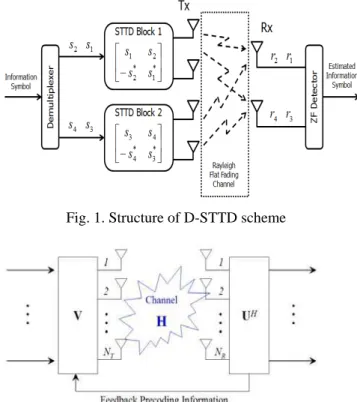
Double - Space Time Transmit Diversity (D-STTD), a scheme suggested by Texas Instruments Corporation, combines MIMO diversity and MIMO multiplexing to get the benefits of both schemes. A D-STTD system is composed by two STTD blocks connected in parallel as depicted in Fig. 1. Each STTD block has two transmit antennas. This parallel structure, which is in essence a diversity scheme, acquires multiplexing characteristics with the combination of the four transmit antennas [6][7].
Fig. 1. Structure of D-STTD scheme
Fig. 2. Basic structure of SVD
B. OFDM scheme
OFDM works very efficiently in multipath fading channels, what makes it a suitable technique for high speed data transmission. OFDM divides the entire frequency selective fading channel can be viewed as many narrow independent flat fading subchannels through which the high-bit-rate data is transmitted in parallel. Thus, OFDM has a better performance than a single carrier system in multipath fading channel conditions. In addition, despite an OFDM signal that is a summation of truncated complex exponential functions with different frequencies, its orthogonality property prevents Interchannel Interference (ICI), and does not undergo Inter symbol Interference (ISI) due to the long symbol duration. At the transmitter, OFDM modulation can be implemented with an N-size Inverse Discrete Fourier Transform (IDFT) on a block of N information symbols. In practice, the IDFT is replaced by the computationally efficient Inverse Fast Fourier Transform (IFFT). At the receiver, the OFDM signal can be demodulated by applying FFT. [8].
C. Pre-coding scheme
At the transmitter, the Pre-coding technique uses the estimated channel information calculated at the mobile station to improve the performance. After operating the weighted vector that can remove the channel interference factor at the transmitter in advance, the signal will be transmitted. So, received signals are only detected as operating the weighted vector simply without the complex detection techniques at the receiver.
1) Pre-ZF and Pre-MMSE detection techniques
As Pre-ZF and Pre-MMSE detection techniques are regarded as Pre-Equalization, ZF and MMSE detection techniques that are used at the receiver in conventional system change to at the transmitter and those techniques are used the same algorithm. Because of that reason, the complexity at the receiver can be reduced [9][10].
2) SVD technique
Once we know the influence of the channel, it is possible to eliminate it using the Singular Value Decomposition (SVD) technique. Since SVD multiplies an orthogonal matrix to the transceiver, unlike Pre-ZF and Pre-MMSE, it does not have to consider the transmit power. Fig. 2 shows the basic structure of SVD, where V is a weighted vector made by feedback information and U is a vector used to recover the original signal (1) [10].
(1)
D. Antenna Subset Selection scheme
The Antenna subset selection scheme increases the number of transmit antennas and secures several channels. MIMO is applied only after estimating the channel that has the best condition. Thereby, the system uses the best channel each time, getting as a result, the optimal BER and throughput performance. There are various methods to estimate the channel condition when using Antenna subset selection. Normally, the channel condition is estimated using the minimum value of SNR. This method is known for having the best performance [11].
E. AMC scheme
The data from the transmitter is coded, modulated, and then transmitted through the channel. The receiver uses the received signal to estimate the condition of the channel and send this information back to the transmitter. The transmitter uses the SNR to makes the channel estimation, and based on that estimation, chooses the level of the Modulation and Coding Scheme (MCS) and adapts the channel coding, interleaving, as well as the modulation structure.
If the channel condition is favorable, a high order modulation and code rate is used. Otherwise, a low order modulation and code rate is chosen.
F. Adaptive-MCM
Through the appropriate MCS level, AMC promotes quality and guarantees the optimal throughput-BER tradeoff according to the channel condition.
G. Adaptive MCM scheme
Adaptive-MCM can be explained using the same description made for the AMC scheme. Nonetheless, in the Adaptive-MCM case, not only the channel coding and
Fig. 3. Block diagram of a MIMO-OFDM system
Fig. 4. The block diagram of the MIMO-OFDM modulation change according to channel condition, but also the MIMO scheme.
H. MIMO-OFDM scheme
Fig. 3 shows the block diagram for a MIMO-OFDM system. At the transmitter, we apply OFDM modulation after the data is passed through channel coding, modulation and MIMO encoding. The OFDM signal goes through the channel and reaches the receiver, which performs the opposite process of the transmitter. Using this system, we can get the diversity and throughput gain provided by MIMO as well as the OFDM’s robustness against frequency selective fading.
I. MIMO-OFDM adaptive-MCM system
In this section, we describe our proposed MIMO-OFDM Adaptive MCM System. Fig. 4 shows its structure using a block diagram.
The Adaptive-MCM System can achieve optimal throughput performance if we apply Pre-coding [9][10] and Antenna Subset Selection [11]. Therefore, we have added those schemes to our system.
III. SIMULATION RESULTS
A. MIMO-OFDM MCM scheme levels and simulation parameters
Table 1 shows the specific combination of MIMO scheme, coding rate and Modulation scheme corresponding to each MCM level. This levels are based on the threshold detection rule i.e., where the throughput has its best performance.
Table 2 shows the simulation parameters for the MIMO-OFDM systems.
1) Performance of the MIMO-OFDM systems
In this section, we analyze the performance of different MIMO-OFDM systems using the parameters in table 2. In Fig. 5 we can see that OFDM OSTBC 4x2, which has the biggest diversity gain, has the best performance. At a BER equal to 10-3, the SNR value is about 5dB. On the other hand, OFDM Layered MIMO 2x2, which is a pure multiplexing scheme, has the worst BER performance. At the same BER, the SNR value is about 30dB. Since, Layered MIMO has no diversity gain; its performance under a fading channel is very close to OFDM 1x1.
The Throughout performance for the different MIMO-OFDM systems is depicted in Fig. 6, where the throughput is measured in Kbps. OFDM D-STTD 4x2 and OFDM Layered MIMO 2x2 have the highest throughput
TABLE2
THE SIMULATION PARAMETERS
PARAMETER VALUE
MIMO
STBC 2x2, OSTBC 4x2, D-STTD 4x2
Layered MIMO 2x2
Channel coding No coding, Turbo 1/2, Turbo 1/3 Modulation QPSK
Channel condition Rayleigh Flat Fading System bandwidth 9MHz
Sampling frequency 10MHz Sampling duration 100nsec
FFT size 1024
Subcarrier spacing 9.765625KHz Occupied symbol time 102.4us Multipath channel tab 12 Maximum delay time 5us
Detection technique Linear ZF, Linear MMSE, Pre-ZF, Pre-MMSE Antenna Subset
Selection Standard : SNRmin
TABLE1
MIMO-OFDM MCM LEVELS
MCM
LEVEL
MIMO
SCHEME
CODE
RATE MODULATION THROUGHPUT
1 STBC 4x2 1/3 QPSK 160 Kbps
performance; about 960Kbps; near twice than OFDM 1x1, which does not apply any MIMO scheme. Nonetheless, OFDM D-STTD 4x2 reaches its maximum throughput at a lower SNR than OFDM Layered 2x2 does. The reason is that OFDM D-STTD has both, diversity and multiplexing gain. As for the other systems, the maximum throughput of OFDM STBC 2x2 is the same as OFDM 1x1, but, as a result of the diversity gain, OFDM STBC 2x2 reaches the maximum throughput with a lower SNR compared to OFDM 1x1; a difference of approximately 15 dB. The system with the better throughput performance at low SNR is OFDM OSTBC 4x2; however, its maximum throughput is only half of the one for OFDM 1x1.
Fig. 5. BER performance of each MIMO-OFDM system
Fig. 6. The throughput of each MIMO-OFDM system
2) Performance of the MIMO-OFDM Adaptive MCM systems
Fig. 7 shows the throughput performance using the parameters corresponding to each MCM level in table 1.
In the case of MCM level 1, the maximum data rate is 160 Kbps; reached at an SNR equal to 0dB. Thereby, if a system uses the values for MCM level 1, such system would get a maximum throughput in the low SNR range; however, the maximum throughput will not surpass 160Kbps.
For MCM level 6 the combination parameters are: OFDM Layered MIMO 4x2, Turbo Code 1/2 and 64QAM modulation. This system has the highest throughput among the six MCM levels: 1440Kbps; nevertheless, to get this value we need a SNR of about 18dB and above, which is very
high in comparison with the other MCM levels. This means that a system that uses the parameters for MCM level 6 has to guarantee enough SNR for its proper operation.
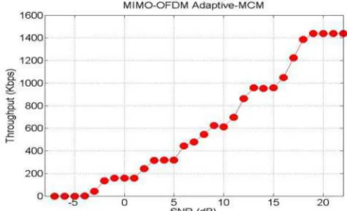
The throughput performance of our proposed system, MIMO-OFDM Adaptive-MCM, is shown in fig.8. We can observe that for a given SNR, the throughput coincides with the system which has the best performance in fig.7 i.e., as SNR increases, the system corresponding to the MCM level with the best throughput performance is used. This is a substantial improvement to the throughput-SNR trade-off and the average data rate compared to a Non Adaptive-MCM system.
IV. CONCLUSION
The MIMO-OFDM Adaptive MCM System changes MIMO scheme, channel coding rate, and modulation scheme, adaptively, according to the channel conditions. And the addition of Pre-coding and Antenna Subset Selection assures a better performance and higher data rate.
Fig. 7. The throughput of each combined MIMO-OFDM level on the Non Adaptive-MCM scheme
Fig. 8. Throughput of combined MIMO-OFDM on the Adaptive-MCM scheme
The MIMO-OFDM Adaptive MCM System achieves a better average throughput performance than a Non Adaptive-MCM system; as SNR increases, the throughput increases almost linearly.
a feasible solution for improving the throughput-SNR tradeoff in the next generation of mobile communication systems.
REFERENCES
[1] S.M. Alamounti, " A simple transmit diversidty scheme for wireless communucarions," IEEE J. Select. Areas Commun., vol. 16, no. 8, pp. 1451-1458, Oct. 1998
[2] V. Tarokh, H. jafrakhani, and A.R. Calderbank, "Space-time block codes from orthogonal designs," IEEE Trans. Inform. Theory, vol. 45, no. 5, pp. 1456-1467, July 1999
[3] V. Tarokh, N. Seshadri, and A. R. Calderbank, "Space-time codes for high data rate wireless communications : performance criterion and code construction," IEEE Trans. Inform. Theory, vol. 44, pp. 744-765, Mar. 1998.
[4] G. J. Foschini, "Layered space-time architecture for wireless communication in a fading environment when using multiple antennas," Bell Labs Tech. J., nol. 1, pp. 41-59, Autumn 1996. [5] E. Bigliery, G. Taricco, and A. Tulino, " Decoding space-time codes
with BLAST architectures," IEEE Trans. Signal Processing, Vol. 50, pp. 2547-2552, Oct. 2002.
[6] E.N. Onggosanusi, A. G. Dabak, and T. A. Schmidl, "High rate space-time block coded scheme : performance and improvement in correlated fading channels," in Proc. IEEE Wireless Communications and Networking Conference, vol. 1, pp. 194-199, Mar. 2002. [7] Texas Instruments, "Double-STTD scheme for HSDPA systems with
four transmit antennas : Link Level Simulation Results," TSG-R WG1 documendt, TSGR1#20(01)0458, Busan, Korea, May, 2001 [8] S.B. Weinstein, " Data transmission by frequency division
multiplexing using the discrete fourier transform," IEEE Trans. Commu. Technol., Vol. COM-19, no. 5, pp. 628-634, Oct. 1971. [9] Michael Joham,, "Linear Transmit Processing in MIMO
Communications Systems" IEEE Trans. on signal processing., Vol. 53, No. 8, August 2005
[10] I. Emre Telatar, "Capacity of Multi-antenna Gaussian Channels" [11] Robert W. Heath, “Antenna Selection for Spatial Multiplexing Systems