3D MESH AUTOMATIC BLANKING AND SPLIT TECHNOLOGY IN URBAN
PLANNING
Hao Feng a, Hong Fan a, Wei Dingb, Zhongbin Zhub, Xiaoming Chenb, Changhua Zhangb
a
The State Key Laboratory of Information Engineering in Surveying, Mapping and Remote Sensing (LIESMARS) of Wuhan Univ., 129 Luoyu Road, Wuhan, China, 430079
b Zunyi Company of China Tobacco, Zunyi
[email protected],[email protected]
KEY WORDS: building model, model segmentation, shape description, visualization, mesh
ABSTRACT:
In 3D digital urban planning applications, a model file may contain multiple building models, however, a single model or model component are very often needed to be used and operated independently. This paper studies 3D model segmentation and blanking technology in 3D urban planning. Three kinds of blanking and segmentation methods are in detail discussed. Finally, a 3D planning prototyping system is developed that include blanking and segmentation functions of the model. The experiment and their results verify the feasibility and efficiency of the method this paper proposed.
1. INTRODUCTION
With the continuous development of spatial information technology and three-dimensional GIS, information, data management and application are transformed from two-dimensional to three-two-dimensional. And with the mature of 3D technology and theory, three-dimensional GIS is also transformed from for show to for a particular area by professionals. Three-dimensional GIS applications also expand. Because of the advantages of three-dimensional GIS – real, intuitive, better visualization, three-dimensional GIS has a good prospect of application in the field of urban planning and decision support.
As the basic element of 3D urban planning, three-dimensional model has a pivotal role in the planning system. Due to the diversity of ways of three-dimensional models, modelling standards are not unique, resulting in poor reusability of 3D models. Since translation, scaling, emphasis are needed for model planning, model hiding is also needed for plans comparison, and model blanking is needed for high-precision models , and area-based blanking is also needs in high-precision planning , model blanking and split technology is very important for urban planning. Therefore, real-time translation, scaling, blanking, and split has become an indispensable part of the three-dimensional urban model planning .The current mainstream 3D real-time rendering API has full support for real time translation, scaling, and emphasis , but cannot support a real time blanking and split. In this paper, varies of real-time three-dimensional model blanking and segmentation techniques for the demand for 3D urban planning are discussed.
2. BLANKING AND SPLIT TYPES
Based on the different functions of the entire city planning system and applicable on different occasions, three-dimensional
model blanking function is divided into the following three categories:
1, overall model blanking 2, subset model blanking
3, partial model blanking (vertex blanking) These three cases are described as follows:
2.1 Overall model blanking
Overall model blanking is used in the following cases: 1) When urban planning system draws the entire scene, as users roaming on the scene, old models will continue to move away from the visible range, new models will enter the user's perspective, when the original models which are within sight removed from the scene, in order to save the resource of the system, they will have an overall blanking.
2) When users clear an area, all models in the cleaning area will be removed, an overall model blanking will be executed. 3) When users operated on a specified area, one model or models will be replaced or hided, they will also have an overall blanking.
Overall model blanking handling methods:
There are two different overall model blanking strategies in this paper based on different functions and blanking situations. For those never re-rendered models, a dispose action will carry on, and they will erase from the memory. For those may re-rendered models, they will not be rendered at first, and they will not be erased from the memory (The meshes and textures are still in the memory), but in the render thread, those models will not have a render action. If after a period of time (Several thread circle), those models are never be rendered, or those models are too far from the frustum (Bigger than a tolerance), those model will be erased from the memory, such as replaced models and far away models. For those NOT needed models, of course, they will be disposed ASAP, so that resources will be released, and
International Archives of the Photogrammetry, Remote Sensing and Spatial Information Sciences, Volume XL-7/W2, 2013 ISPRS2013-SSG, 11 – 17 November 2013, Antalya, Turkey
This contribution has been peer-reviewed.
for those temporally NOT needed models, they will be stayed at memory, it can reduce the IO operation, and make the system smoother. Different conditions and situations of overall model blanking is shown in table 1:
Table1: Different conditions and situations of overall model blanking
Model type Blanking Time
Blanking strategy
Reload needed
Models for remove
Users apply remove action
Dispose from memory, stop rendering
NO
Models out of frustum temporally
Models out of frustum when browsing
Stop rendering but models are
still in
memory
After dispose and re-enter frustum , reload happens Multiple plans
models
Users switch the plan
top rendering but models are
still in
memory
When users
apply reload action
2.2 Subset model blanking
When carrying on urban planning, after a whole plan (Also after the Overall model blanking) , users will carry on a detail planning and processing for some important areas. But only hide, transform or scale actions are not enough, so model blanking based on subset is needed.
A mesh is composed of several subsets, and a subset is a group of triangles which used same attributes (textures, materials and render state). Normally, different model part uses different attribute. Figure 2 shows a mesh of a house, and it is split for several subsets. A model blanking method based on subset can have a partial model hide without changing the model mesh, so that a more meticulous mesh operation can be carried on.
House
Subset0:Floor Triangles render
by floor’s
attribute
Subset1:Wall Triangles render
by wall’s
attribute
Subset2:Roof Triangles render
by roof’s
attribute
Subset3:Window Triangles render
by window’s
attribute
Figure 2 A house is split for several subsets
Users can hit the model or marquee a subset and pick it, hide it or emphasize it. The planning system will render the subsets of the model according on the users’ settings, so that emphasize and hide can be carried on.
2.3 Partial model blanking (vertex blanking )
When subset model blanking cannot meet users’ commitment, it means system will split a subset of a model; a tinier hiding element is needed. So we choose a triangle as the hiding element. This is vertex blanking.
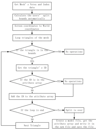
The process of vertex blanking is showed in figure 1:
Get Mesh’s Vetex and Index
data
Calculate the users’ split
bounds automatically
Screen coordinates to World coordinates
Loop triangles of the mesh
If the loop is end Split is over
Add the ID to the attribute array If the triangle is in the
bounds
Next Triangle
No operations
NO
NO
NO
Yes
Create a model file, get the attribute array and write it in
the new file and save the file
Get the triangle’s ID
If the ID is in the
attribute array YES No operations
YES
Vertex blanking needs a boundary; it can be a line, a rectangle or a polygon. This boundary need to be projected onto a plane in order to clear if the model is divided. In this paper, we use a model orthographic to split the model. If the system determines that a model in the planning process, stacked or covered, the system will automatically calculate the segmentation range, if users need to manually determine the partition boundaries, they can also manually click the boundary.
After the boundary is determined, a model partial split based on model index changing will be carried on. We’ll discuss this method in detail. In order to do a model partial split, model’s attributes are needed. Table2 shows the needed attributes.
Table2 Needed attributes for model partial split
Model Info Gather method Gather purpose
Vetex Buffer GetVertexBuffer Gather Vetex info, an get coordinates and texture info from Vertex buffer
Index Buffer GetIndexBuffer Gather model index info, get every triangle info
Attribute Table
GetAttributeTable Gather model attributes, and get every subset's attributes Subset
Number
GetSubSetNum Gather the subset number of the model, since subset split is based on subset, it is a preparation for the next step of blanking
Vertex format
GetFVF Gather the format of the
vertex, incluing coordinates, texture , etc
Vertex Number
GetNumVertices Gather the number of vertex, for index calculation
Bytes per
vertex
GetNumBytesPerVertex Gather how many bytes a vertex needs
Face Number GetNumFaces Gather face number of a
model, so that users can loop them
Split index
and Split
temp index
Split1Index Split2Index
For vertex for render and for vertex for hide
Source Index SourceIndex For rearranged vertex
Split index NumSplitIndex Split vertex boundary
International Archives of the Photogrammetry, Remote Sensing and Spatial Information Sciences, Volume XL-7/W2, 2013 ISPRS2013-SSG, 11 – 17 November 2013, Antalya, Turkey
This contribution has been peer-reviewed.
number
Is Index
Changed
bIndexChanged If index rearrangement is
over , it is TRUE, otherwise it is FALSE
After gathering all the information of the model in the table, we will have a model index rearrangement.
1, Apply storage space for rearranged vertex index based on subset number, and give them a initial value -1;
2, Loop for all the vertex based in subset, and rearrange every vertex of a subset.
3, In a subset, loop every vertex, three vertex one time(one triangle). During the loop, judge the triangle's position of the boundary, and note the vertex number of triangles and vertex within the boundary. The vertex number is the boundary number of the subset.
4, Loop the subset again, rearrange the index and use the temp space. Put the vertex which will be rendered in front of the index, and put the vertex which will be blanked in back of the index.
5, Loop the step 1-4 and rearrange every subset of a model, and set bIndexChanged to TRUE. This is the end of a model's rearrangement.
Figure 3 shows the whole blanking process.
Subset0 render vertex
Subset0 hide vertex
Subset1 render vertex
Subset1 hide vertex
Subset2 render vertex
Subset2 hide vertex
… … Subset n
render vertex
Subset n hide vertex Subset0 Vertex
Index
Subset1 Vertex Index
Subset2 Vertex
Index …
Subset n Vertex Index
Render vertx
Hide vertex
Render vertex
Hide vertex
Rearrange vertex
Original vertex index
Vertex rearrangemen
t
Calculate a index boundary
Render
Figure3 The whole blanking process
After rearranging the vertex based on split boundary, the model will be rendered according to the split boundary, and based on subset. It means that every subset, only the vertex before the split index boundary will be rendered, and those vertex behind the split index boundary(NOT in the split boundary) will N be rendered, In this way a model is blanked.
3. BLANKING AND SPLIT PROCESS IN DETAIL
Since the automatic model blanking and split technology is a part of 3D urban planning, we will have a introduction of blanking and split process in detail, as figure 4.
Model Blanking
Subset blanking Overall blanking
Partial blanking
User browse Hit the model and blank
Hit a subset and blank Blank a subset automatically
Users set bound and blank Auto bound and blank cal
Model split and
save Figure 4 Blanking and split process in detail
The blanking and segmentation of the model are event driven. With the rotation of the lens when the user is planning, the removed part of the model needs to be overall blanking. When users need to hide a building, the user clicks, the system will call the overall blanking of the model. Similarly, when users need to hide a part of the model, based on the difference of the
user invokes the input (may select a subset or click on a polygon range), the system will call the part of the blanking based on a subset of vertices rearrangement. The most common situation is that the user to import a new model during the adjustment of the model, the new model will collide with the original imported model, that is the intersection of the scope of the model, this time, the surface projection of the model are adjusted, the system will automatically calculate the blanking area of the polygon, the first imported model will have a blanking, thus avoiding the model overall blanking bring the observation incomplete. When users choose to save the planning, the system will automatically need to partially blanking model is divided save, which would call model segmentation and save module.
4. EXPERIMENTS AND RESULTS
In order to verify the automatic blanking and segmentation techniques of the three-dimensional model in urban planning, we developed a 3D planning system based on the above described technologies. Through the planning system, users can easily achieve the following six levels of planning, adjusting, query, display: Planning system (System) -> project (Project) -> plan (Plan) -> model (Model) -> subset (Subset) -> metadata (Metadata).
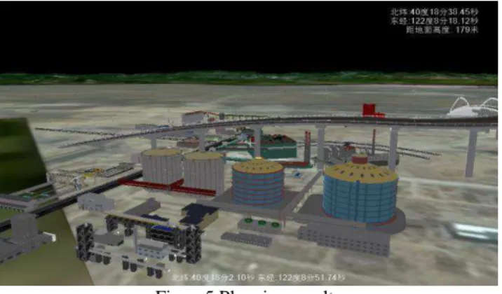
Through systematic planning function, users can easily achieve: set planning region, creating a new planning, import model into a planning, query model details and other operations. Meanwhile, in order to facilitate the user operation, navigation, highlighting, query operations are implemented at every level. Figure 5 is a steel factory’s planning result. This planning results used 71 three-dimensional model, the total number of triangles in all models is up to 300,000. On ordinary PC(including portables computer), this system can run smoothly, to achieve system 's full frame (the system has limited to the 30 frames per second). The system can automatically be based on user browsing perspective and position of the model to conduct the whole blanking. Asynchronous loading technique of the model is also adopted, effectively reducing the waiting feeling of the model loading, and also make the overall user experience more fluid and natural.
Figure5 Planning result
Meanwhile, in order to test and demonstrate blanking and segmentation technology, we have developed a complete model blanking and segmentation platform, which provide the friend UI to allow users to easily conduct segmentation, blanking, and stressing of the model.
Figure 6 shows a model composed of multiple building, before lanking fore and after blanking emphasis display division section separation effect.
International Archives of the Photogrammetry, Remote Sensing and Spatial Information Sciences, Volume XL-7/W2, 2013 ISPRS2013-SSG, 11 – 17 November 2013, Antalya, Turkey
This contribution has been peer-reviewed.
Figure6 Multi-building model blanking
Figure 6, the upper part is the original status of the entire model, the middle part is the results that a part of model is blanking due to the user clicking. The lower part is a emphasis display of the model, where the blue part stands for blanking parts, the red part stands for retained parts.
This model contains 14483 vertices, 24317 triangles, vertex index-based automatic segmentation and blanking technology are used to complete cutting and blanking real-time in 0.01 seconds.
Finally, the segmentation platform functionalities are integrated into the planning system, which completed automatic blanking and segmentation function of the model in the planning system that include the support of user-defined model's blanking and segmentation.
5. CONCLUSION
Three-dimensional model of blanking and segmentation is an essential part of three-dimensional urban planning, three different types of model blanking and segmentation strategies in the field of urban planning process involved in building models are analyzed and designed. Some experiment results are given to verify the methods. Although these methods are specially designed for the three-dimensional digital model urban planning. They also have potential application value in other 3D applications.
6. ACKNOWLEDGEMENTS
This work was supported by the National High Technology Research and Development Program of China (Grant No. 2012AA121401),
7. REFERENCE
[1] Ray casting [EB/OL].
http://en.wikipedia.org/wiki/Ray_casting
[2] Qing Zhu .3D GIS development[J].GIS World, 2004-6:31-33
[3] Qing Zhu, Yurong Gao. GIS 3D Model Building [J],
Wuhan University of Technology (Information Science Edition); 2003,03:283-287
[4] Frank D Luna, DirectX 9.0 3D Game Programmer Guide, Tsinghua university press, Beijing, March 2007.
[5] Rettmann M E,Hart X,Prince J L.Automated sulcal segmentation using Watersheds on the cortical surface. Neuro Image,2002,l 5(2):329-344.
[6] Microsoft, DirectX Document, Microsoft, Microsoft DirectX development kit, June 2010
[7] Vincent L、Soille P.Watersheds in digital spaces:An efficient algorithm based on immersion simulation[J]. IEEE Transactions on Pattern Analysis and Machine Intelligence,
1991,13(6),583-598.
[8] Lazarus F、Verroust A. Level set diagrams of polyhedral objects[J]. Proceedings of the 5th Symposium on Solid Modeling and Applications,1999,130-140.
[9] BischoffS 、 KobbeltL. Ellipsoid composition of 3D models[J]. Proceedings of International Symposium on 3D data Processing Visualization and Trancmission,New York,IEEE Computer Society Press,2002,480-488.
International Archives of the Photogrammetry, Remote Sensing and Spatial Information Sciences, Volume XL-7/W2, 2013 ISPRS2013-SSG, 11 – 17 November 2013, Antalya, Turkey
This contribution has been peer-reviewed.