THE DEVELOPMENT OF SPECIAL SEQUENTIALLY-TIMED
CHARGES FOR BREAKING FROZEN WATERWAYS
Stanislav LICHOROBIEC
1, Karla BAR
Č
OVÁ
2, Tomáš DORAZIL
3, Radovan SKÁCEL
4,
Ladislav ÍHA
5, Martin
Č
ERVENKA
61 VŠB – Technical University of Ostrava, Faculty of Safety Engineering, Ostrava, Czech Republic, [email protected] 2 VŠB – Technical University of Ostrava, Faculty of Safety Engineering, Ostrava, Czech Republic, [email protected] 3 VVUÚ, a.s., Pikartská 1337/7, Ostrava - Radvanice, Czech Republic, [email protected]
4 Explosia, Inc., Semtín 107, Pardubice, Czech Republic, [email protected] 5 Explosia, Inc., Semtín 107, Pardubice, Czech Republic, [email protected]
6 Fire Brigade Hodonín (HZS ČR), t . b í. Čapků 3, Hodonín, Czech Republic, [email protected]
Abstract: This article documents the development of the noninvasive use of explosives during the destruction of ice mass in river fl ows. The system of special sequentially-timed charges utilizes the increase in effi ciency of cutting charges by covering them with bags fi lled with water, while simultaneously increasing the effect of the entire system of timed charges. Timing, spatial combinations during placement, and the linking of these charges results in the loosening of ice barriers on a frozen waterway, while at the same time regulating the size of the ice fragments. The developed charges will increase the operability and safety of IRS units.
Keywords: Sequence, timed charge, explosive, ice barrier, sealing bag.
Research article
Introduction
A continuously frozen waterway surface or accumulated layers of ice that have formed during the winter season, usually during a sudden thaw, signifi cantly deteriorate the fl ow rate of these waterways and in most cases are an obvious cause of local fl ooding. The result is damage to property and in particular a threat to the safety, lives and health of the population. Two types of procedures are currently used to break and remove these barriers, depending on local conditions.
The fi rst is the utilization of a mobile construction excavator, which breaks the ice and extracts it out of the river channel, or the ice is gradually loosened via heavy duty fl oating machinery that moves within the channel and uses its weight to gradually disrupt the ice, which is then taken away by the fl ow of water.
The second approach is the utilization of commercial explosives, which are placed on or below the ice, and the water barrier is removed by controlled blasting as part of destruction work.
The development and employment of special sequentially-timed charges creates a third, signifi cantly easier and safer procedure for both
machinery and the actual IRS employees who carry out this activity. This new approach signifi cantly accelerates the disruption of problematic points of the frozen waterway. In addition, small detonated charges combined sequentially in rows and covered with a water bag eliminate the negative effects of ice fragmentation and minimize risks to surrounding objects and persons involved. When using this procedure, the magnitude of impact and consequent pressure waves in the water are considerably smaller than when using charges fi red under the ice, which results in signifi cantly less risk to aquatic organisms.
The formation of ice barriers
Ice barriers can develop in different ways and be of a different nature, but in principle the following two models are concerned. It is either a continuous frozen surface, or the barrier is formed from accumulated ice.
The fi rst model – a continuous frozen surface is formed on a slowly fl owing river during long-lasting and intense freezing temperatures.
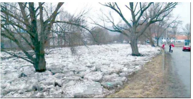
during periods of rapid and signifi cant warming, when the volume of water in the river increases substantially due to the massive melting of snow. The increase may also be enhanced by rainfall. This leads to a massive increase in fl ow rate and water-level rising. The continuous frozen surface gradually melts, cracks, and is carried away farther downriver in the form of icebergs. In the event that there is some obstruction in the channel – a fallen tree, water weir, bridge abutments, etc., or there is a change in profi le, velocity or fl ow direction, the fl oating blocks are usually captured, gradually forming an ice barrier and reducing the fl ow profi le of the river. However, it also causes an outpouring of the river from the channel and the fl ooding of adjacent areas.
Fig. 1 A continuous ice layer on a waterway
Fig. 2 The accumulation of ice on a waterway
Materials and Methods
Procedures for removing ice barriers
A suitable procedure for removing ice barriers is proposed with regard to the particular circumstances and nature of the waterway. An important consideration when choosing the right technique is the evaluation of the width of the fl ow and the expected behavior of the released ice further downstream. In the case of smaller rivers and streams, mobile construction equipment is
advantageously utilized to break the ice sheet. In such a case, excavators move within the riverbed, or if the terrain allows it, the ice is removed directly from the banks. The continuous disturbance of the ice layer and its gradual washing away is also carried out by heavy duty fl oating rescue machinery, which moves over the ice or in the bed of the stream and uses its weight to attempt to shatter and break the layer of ice.
Fig. 3 and 4 The disruption of ice barriers using mobile excavators or fl oating tracked transporters
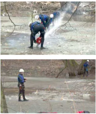
Fig. 5 and 6 The preparation of holes for the placement of charges and the placement of charges
beneath the ice surface
The charges are placed under the ice into carved or drilled holes which must be prepared in advance. The charge is attached to a wooden cross and adjusted by initiators. A thus prepared charge is inserted under the ice into the prepared holes. Consequently, a detonating electric circuit is linked and prepared for blasting, see Fig. 5 and 6. Throughout this period, the persons preparing the blasting, usually members of the IRS, walk on the frozen water surface. It is therefore a relatively time-consuming activity, during which there is a constant risk of ice breaking and someone falling into the water, especially when the layer of ice is unstable, discontinuous, or of unequal thickness.
The system of sequentially-timed cutting
charges
The system of sequentially-timed cutting charges is an alternative method to using explosives. Its advantage is that it considerably minimizes the negative effect of ice fragmentation and its scatte-ring into the surroundings, as well as restricting the movement of workers on often unstable ice.
The technical solution proposal is based on the use of precisely timed cutting charges placed on the ice. To enhance the effect of the blast on the ice, the charges are sealed from the top with tex-tile water bags specifi cally developed for this purpose. This method is not as effective as the ap-plication of charges under the ice. However, the effect is
considerably higher than it would be if the charges were simply placed on the ice.
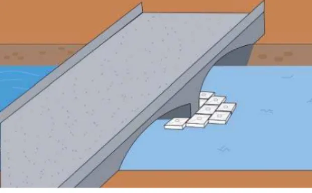
The main advantage of the developed process is that water bags in the form of a seal absorb the rear end of the explosion energy above the charges and reduce the scattering of fragmented pieces of ice and captured frozen silt into the surroundings. Precise timing and optimum place-ment of these specifi cally-defi ned charges on the surface enable us to achieve the expected effect while breaking the ice layer and regulate the amount of loosened ice. Due to the minimalization of adverse effects of this type of blasting on the area, it will be possible to utilize this system in the vicinity of industrial or residential buildings, or buildings connected with river fl ow, especially near bridges, water weirs, jetties, or vessels frozen in ice.
Preparation of sealing water bags and the loading of adjusted charges is performed outside of the waterway. The bags with charges are then placed on the ice in predetermined positions based on the evaluated situation. After fi lling the bags with water, which is usually pumped directly from the waterway, and their attachment to the preloaded elastic rope, the system is ready to blast. Attaching the bags to elastic ropes is important, as it secures them against being torn downstream by loose ice mass. After blasting, the bags are spontaneously pulled out of the water or out of the way of the loosened ice mass, so as not to become an obstacle for the possible subsequent river-fl ow.
The system is designed so that most of the preparatory work is carried out away from the waterway, also to minimize the time during which members of the Integrated Rescue System spend on the frozen river.
Results
Accelerating mass – layers of ice via
explosion
The most famous example of accelerating matter in the context of the monitored use of explosives is rock and mineral mining (Pravda and B tík, 2010; Dojčár et al., 1996; Cooper and Kurovski, 1996).
The most appropriate analogy for accelerating ice using an explosive charge can be applied using the so-called Gurney model, from which the speed of fragments accelerated by explosion is derived (Vávra and Vágenknecht, 2004).
is divided into the acceleration of inert material in the form of kinetic energy and the energy transferred by gaseous products of detonation (Vávra and Vágenknecht, 2004; Zukas and Walters, 1998).
The resulting gaseous products have a spatially uniform density and linear 1D velocity profi le in the spatial dimensions of the system. Primarily, the proportion of energy from the total energy which is usable for accelerating the mass is represented by dimensions of velocity [km.s-1], characteristic
of each explosive, or for its density, and is marked as (2E)1/2, also known as the Gurney Constant.
The exact determination of the value is performed experimentally via the so-called "cylinder" test (Vávra and Vágenknecht, 2004).
For the explosive Semtex-10 SE at the given tabular density of 1,44 g/cm³, the Gurney Constant 2E is set at a value of 2,3 to 2,5 km/s [1]. According to the specifi c explosive used, this value can be calculated from the determined velocity of detonation "D" of the specifi ed explosive, using the equation (1) (Vávra and Vágenknecht, 2004):
(1)
where: 2E – Gurney Constant [km/s], D – detonation velocity [km/s], 2,97 – experimentally determined coeffi cient.
After inserting the detonation velocity value of the given explosive – D = 7,2 km/s into this equation (1), the value of Gurney Constant is 2E = 2,43 km/s.
Since the assembly of the shaped water charge will be placed on ice of differing depth, the mathematical model for calculating the effectiveness of this assembly was taken from the structural analogy as an asymmetrical sandwich (Vávra, 2002). The mathematical equation for the accelera-tion of ice as an underlay using a blast of explosives is given in the ordering of this sandwich in the succession - ice / explosive / seal - L / T / U. The scheme of the sandwich arrangement would be as follows, see Fig. 7, wherein:
L – ice layer as an underlay, T – explosive used, U – seal – body of water in the bag.
Fig. 7 Scheme of the structural design of the so-called asymmetrical sandwich, for the calculation of accelerated particles in the explosion
(Vávra and Vágenknecht, 2004)
The mathematical calculation of the acceleration of the ice mass away from the explosive during explosion is based on equations (2) and (3) (Vávra and Vágenknecht, 2004):
(2)
(3)
where: v – the velocity of accelerated particles of the ice mass [km/s], 2E – Gurney Constant [km/s],
L – weight of seal [kg], T – weight of explosive [kg],
L – weight of ice underlay [kg].
Segment L can be considered the block of the ice, which is identical to the base of the sealing bag of water multiplied by the diameter of the ice layer.
The development of the system of special sequential charges
The system described consists of three components:
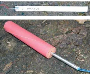
1 - the explosive used – a relatively wide range of industrial and specialty explosives can be used for the removal of ice barriers. A higher brisance of the explosive contributes to a fi ner fragmentation of the ice, a greater work ability in turn increases the overall volume of loosened ice mass. The explosive must also be waterproof and capable of initiation and detonation in diameters of up to 30–35 mm. One of the commonly used commercial explosives that fulfi ll these requirements is small diameter dynamite. A second alternative could be special plastic type explosives like Semtex Pl SE M, prepared in the form of relatively thin strips.
Fig. 8 and 9 Plastic explosive Semtex Pl SE M and industrial explosive Perunit E – Ø 28 mm
2 2,97 D E __ __ __ __
1 3 2 2 1 3 1 2v A U L
A
A T T
The following two types of explosives were therefore chosen from the products of the company Explosia Pardubice, Inc., namely the special plastic explosive Semtex Pl SE M with a detonation velocity of 7200 m/s and the industrial explosive Perunit E with a detonation velocity of 5500 m/s. Both explosives are suffi ciently water-resistant and therefore suitable for the expected conditions of use. Semtex Pl SE M additionally meets the requirements of ecological explosives – see Fig. 8 and 9.
2 - textile sealing bags – the structure of the sealing bags was designed with regard to their suffi cient sturdiness during handling and fi lling with water and their resistance to detonation. Their design allows for the insertion of adjusted explosives with a detonator in the pocket located on the external bottom side of the bag, the fi xation of detonators using a gripping eye against being pulled out of the charge during the placement of bags on the surface or while fi lling them with water.
Fig. 10 and 11 The placement and fi xation of a charge in a sealing bag and subsequent fi lling
with water
Fig. 12 and 13 Stacking textile sealing bags and a transport bag for tranport
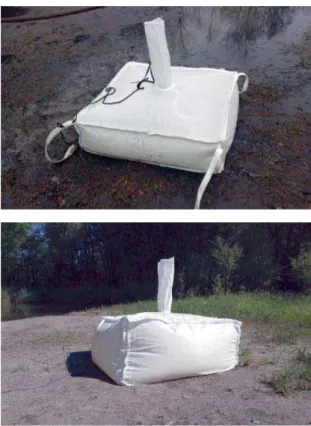
Fig. 14 and 15 Photo of the developed textile sealing bag with a volume of 250 and 500 liters
of water
All the parts of the bag, including the fi lling sleeve, are made of a soft textile material. During an explosion and the bursting of the bag, no projection of solid fragments therefore occurs. The bags can be linked together at the handles at the corners. These handles also serve to attach the bag to the elastic ropes and are pulled out of the way of loose ice mass after an explosion. The fi lling sleeve is positioned in the middle of the upper side of the bag and after fi lling it is possible to fasten and close the bag. At least one other bag can be placed upon this closed bag, thereby increasing the level of the water column above the charges. This action once again increases effectiveness – the impact of the explosion shock waves towards the ice surface. The bags are manufactured in standardized volumes of 250 or 500 liters, with a square base of about 1 m2. For
transport they are easily storable in groups of three to fi ve pieces in a transport bag.
3 - Initiation – Both an electric and a non-electric ignitor can be used as an initiation system, as well as timed electronic initiation systems. As for the possibility of setting arbitrary sequential initiation times, it is advantageous to use a system of variable electronic timing in practice. For longer times with less precision of timing in the range of 25 ms to 75 ms, an electric detonator was designed. The initiation times were selected with the aim to achieve a maximum seismic effect while using defi ned charges at predetermined spacing.
Discussion
Seismic effi ciency measurement system
The seismic measuring of the effectiveness of the developed directed special charges was conducted by Austin Detonator, Ltd. and Geodyn, Ltd., using a measuring set of vibrographs-geophones, type Instantel MiniMate plus, BE 7901, 9146 and 13846. The measurement was carried out in four directions perpendicular to the center of the fi rst charge, including noise measurement using a linear microphone with a weighting fi lter, see Fig. 17. The geophones were placed at a distance of 10 meters from the center of the fi rst charge and an additional geophone was placed in the direction of the sequential timing at a distance of 7,5 m. Two directed charges with a fi xed sequential timing were always blasted at once.
Fig. 17 A view of the used geophones from the companies Austin Detonator Ltd. and Geodyn, Ltd.
Fig. 18 Spatial distribution of the geophones used in the conducted seismic tests
The spatial placement of geophones is documented in Fig. 18. An example of the result of individual seismic measurements is shown in the following chart, which projects outputs with individual geophones, including the mathematical calculation of the total energy effi ciency.
Energy effi ciency – the indication "Total PVS Energy" was based on the length of the sequence timing and the distance between the placed charges. Each graph, see Fig. 19 and 20, clearly shows a marked difference in size of this energy when placing the charges at a distance of one meter or two meters, at a timing of 2 ms and 4 ms.
The practical application of the developed
system in practice
The utilization of the developed system of special sequential charges in practice is very variable. Its main advantage is that it can be prepared on the
bank and then moved to the ice and fi lled with water. The possible placement and sequential timing of the initiation system is provided as a visual graphical representation, see Fig. 23, 24 and 25.
Fig. 21 and 22 Colored observations of the energy effi ciency of measurements depending on the time and oscillation frequency of seismic waves
Fig. 23 and 24 The location of charges for breaking the ice mass
Fig. 25 The loosening of frozen areas at bridge piers
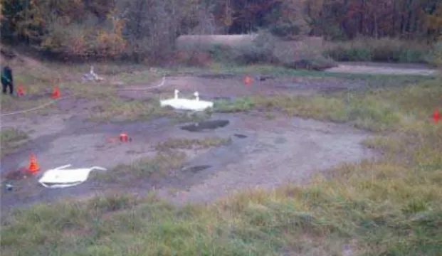
Fig. 26 Field tests of charges on artifi cially created ice blocks
At the time of the special charges fi eld tests the weather was extremely warm, so it was impossible to carry out practical testing on real ice. Therefore, artifi cial ice cubes were created and the tests were conducted on these – see Fig. 26 and 27.
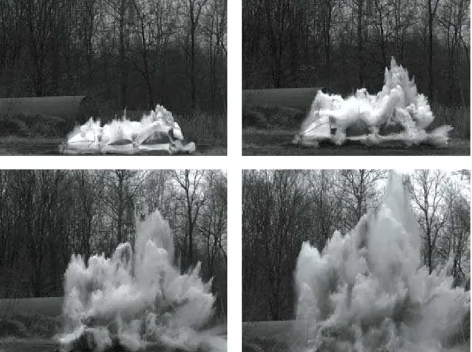
Fig. 27 Test result – the fragmentation of ice blocks
Fig. 27 clearly shows the total crushing of ice blocks by the shockwave, as should occur in real life on a frozen ice mass.
Ensuring safety during blasting works
The above mentioned blasting works require following certain safety rules, and according to local conditions, a so-called safety circuit and handling space must be determined (Müncner et al., 2002).
Safety circuit – the perimeter of an area endangered by the effects of the planned blasting, especially material projected by the pressure wave and poisonous fumes. It must be secured by patrols or in another appropriate manner determined by the organization so as to prevent the entry of outsiders into the affected area.
Affected area – must be vacated and the safety circuit must be closed prior to charging the explosives and prior to connecting the detonation network to the supply line.
However, one can assess from experiment fi ndings that these areas will be substantially smaller than they would have to be in the case of explosives placed freely on the ice surface, or below in the water, as the temporal sequence of charge blasting in Fig. 28 to 31 shows.
Conclusion
The development of the system of sequentially-timed charges was practically completed in the second half of 2015. The effect of the charges on an actual frozen surface has so far only been simulated on a replacement of subsoil, and practical tests in real conditions will be implemented in collaboration with rescue units under suitable climatic conditions. During these tests, the evidence collected from the tests carried out until now will be utilized. The effectiveness of the system with a variable depth of the ice, the effect of timing on the resulting seismic effects, the behavior of the ice layer and functional reliability tests of the whole systém will all be verifi ed.
However, it is already possible to say that the use of precise timing in the initiation of electronic detonators in a very short time [ms] allows for a substantial increase in the detonation energy of charges in the sequential system. Thus, a relatively small mass of charges can disrupt a relatively thick layer of ice, and even move it in the desired direction. The use of small, water-sealed charges renders the
entire ice rupturing process much safer than during the use of substantially larger charges located on the surface of the ice barrier or directly below it in the waterway.
Textile sealing bags contain no solid component which could act as a secondary source of projection of shrapnel in the explosion, therefore an explosive system designed in this way will allow ice barriers on waterways to be disposed of safely and in close proximity to urban areas, buildings, bridges, roads, water dams, frozen ships etc., and at the same time without negative consequences to aquatic life below the surface.
Acknowledgement
The development of the aforementioned charges was possible thanks to project no. VG20132015117, entitled: "Special Precise Sequentially-timed Charges for Crisis Management", which was approved and implemented under the Security Research Programme of the Ministry of Interior of the Czech Republic in the years 2010–2015.
References
COOPER, P.W.; KUROVSKI, S.R. (1996): Introduction to the Technology of Explosives, VCH Publ., USA. DOJČÁR, O.; HORKÝ, J.; KO ÍNEK, R. (1996): Trhacia technika [Blasting Technology], Mon-tanex, a. s.,
Ostrava, ISBN 80-85780-69-0. (in Slovak)
MÜNCNER, E.; a kol. (2006): Príručka pre strelmajstrov a technických vedúcich odstrelov [Guide for Blasters and Technical Leadership for Blasting], SSTVP Banská Bystrica, ISBN 80-968748-4-5. (in Slovak)
PRAVDA, V.; B TÍK, J. (2010): Trhací práce v hornictví, stavebnictví a speleologii [Blasting work in mining, construction and caving,], Montanika o. s., Vestec u Prahy, ISBN 978-80-254-8542-2. (in Czech)
VÁVRA, P.; VÁGENKNECHT, J. (2004): Teorie působení výbuchu [The theory of operation of explosion], Univerzita Pardubice, Fakulta chemicko-technologická, ISBN 80-7194-494-7. (in Czech)