DESIGN OF SIMULINK MODEL FOR
OFDM AND COMPARISON OF
FFT-OFDM AND DWT-FFT-OFDM.
ROHIT BODHE
Electronics and Telecommunication department, Student, ME (Microwave) Pune Institute of Computer Technology, University Of Pune
Pune, Maharashtra, India [email protected]
SATISH NARKHEDE
Electronics and Telecommunication department, Professor, Pune Institute of Computer Technology, University Of Pune
Pune, Maharashtra, India [email protected]
SHIRISH JOSHI
Director, Applied Digital Microsystems Pvt. Ltd. Mumbai, Maharashtra, India
Abstract:
Growth in technology has led to unprecedented demand for high speed architectures for complex signal processing applications. In 4G wireless communication systems, bandwidth is a precious commodity, and service providers are continuously met with the challenge of accommodating more users within a limited allocated bandwidth. To increase data rate of wireless medium with higher performance, Orthogonal Frequency Division Multiplexing (OFDM) is used. Recently Discrete wavelet transforms (DWT) is adopted in place of Fast Fourier transform (FFT) for frequency translation. Modulation schemes such as 16-QAM, 32-QAM, 64-QAM and 128-64-QAM (Quadrature amplitude modulation) have been used in the developed OFDM system for both DWT and FFT based model. In this paper we propose a DWT-IDWT based OFDM transmitter and receiver that achieve better performance in terms Bit Error Rate (BER) for AWGN channel. It proves that all the wavelet performs better over the IFFT-FFT implementation.
Keywords: OFDM; FFT-OFDM; IFF; DWT-OFDM; IDWT 1. Introduction
The communication systems and communication networks of the future will fundamentally improve the way people communicate. One among the services expected to have major impact in the future include wireless communication that will permit mobile telephony and data transfer anywhere on the planet . Delivering and receiving these services to the large and rapidly growing commercial markets has created new technological challenge in signal design, modulation, detection, and signal processing.
For wireless communication systems, limited bandwidth allocations coupled with a potentially large pool of users restrict the bandwidth availability to the users. The success of wirelesses communication systems thus depends heavily on the development of bandwidth efficient data transmission schemes. Wireless multicarrier modulation (MCM-OFDM) is a technique of transmitting data by dividing the input data stream into parallel sub streams that are each modulated and multiplexed onto the channel at different carrier frequencies.
Since there is no cyclic prefix present in wavelet implementation the data rates can surpass those of FFT implementations.
The Wavelet transform is a way of decomposing a signal of interest into a set of basis waveforms, called wavelets, which thus provide a way to analyze the signal by examining the coefficients (or weights) of wavelets. This method is used in various applications and is becoming very popular among technologists, engineers and mathematicians alike. In most of the applications, the power of the transform comes from the fact that the basis functions of the transform are localized in time (or space) and frequency, and have different resolutions in these domains. Different resolutions often correspond to the natural behavior of the process one wants to analyze, hence the power of the transform. These properties make wavelets and wavelet transform natural choices in fields as diverse as image synthesis, data compression, computer graphics and animation, human vision, radar, optics, astronomy, acoustics, seismology, nuclear engineering, biomedical engineering, magnetic resonance imaging, music, fractals, turbulence and pure mathematics.
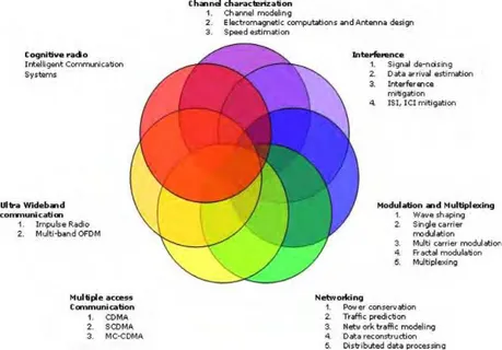
Recently wavelet transform has also been proposed as a possible analysis system when designing sophisticated digital wireless communication systems, with advantages such as transform flexibility, lower sensitivity to channel distortion and interference and better utilization of spectrum. Wavelets have found beneficial applicability in various aspects of wireless communication systems design including channel modeling, transceiver design, data representation, data compression, and source and channel coding, interference mitigation, signal de-noising and energy efficient networking. Fig.1 gives a graphical representation of some of the facets of wireless communication where wavelets have been used [1].
A combination of modulation and multiplexing constitutes to Orthogonal Frequency Division Multiplexing (OFDM). Independent signals that are sub-set of a main signal are multiplexed in OFDM and also the signal itself is first split into independent channels, modulated by data and then re-multiplexed to create OFDM carrier. Orthogonality of subcarriers is the main concept in OFDM. The property of orthogonality allows simultaneous transmission of additional sub-carriers in a tight frequency space without interference from each other. This acts as an excessive advantage in OFDM.
With the help of OFDM, sufficient robustness can be achieved to provide large data rates to radio-channel impairments. In an OFDM scheme, a large number of orthogonal, overlapping narrowband channels or sub-carriers are transmitted in parallel by dividing the available transmission bandwidth. Compact spectral utilization with utmost efficiency is achieved with the help of minimally separated sub-carriers. Main attraction of OFDM lies with how the system handles the multipath interference at the receiver end. OFDM is multicarrier modulation (MCM) technique which provides an efficient means to handle high speed data streams on a multipath fading environment that causes ISI. Normally OFDM is implemented using FFT and IFFT’s.
To decrease the bandwidth waste brought by adding cyclic prefix, wavelet based OFDM is employed. Due to use of wavelet transform the transmission power is reduced. The spectral containment of the channels is better since it does not use cyclic prefix. One type of wavelet transform is Discrete Wavelet transforms that have been considered as an alternative platform for replacing IFFT and FFT. It employs Low Pass Filter (LPF) and High Pass Filter (HPF) operating as Quadrature Mirror Filters satisfying perfect reconstruction and orthonormal properties. The purpose of this paper is to perform the simulation study of FFT and DWT OFDM systems with respect to BER for AWGN channel for various modulation schemes. In DWT OFDM system, zero padding and vector transposing is done to transmit the modulated signal. The DWT has been introduced as a
Fig 1: The scale of wavelet applications for wireless communication
2. OFDM Systems
2.1FFT based OFDM system
Orthogonal Frequency Division Multiplexing (OFDM) scheme is based on the multicarrier communications technique. In OFDM the spectra of subcarriers overlap on each other but the frequency spacing between them is selected such that the subcarriers are mathematically orthogonal to each other. Fig.2 shows a block diagram of a basic OFDM system. Discrete Fourier Transform (DFT) efficiently implemented by Fast Fourier Transform (FFT) is used to modulate and demodulate the data constellations on the orthogonal sub-carriers. This baseband signal processing algorithm effectively replaces the bank of I/Q modulators and demodulators that would otherwise be required [3].
An OFDM trans-receiver is shown in Fig.1 the inverse transform block can either be IDWT/IFFT and forward transform block can be DWT/FFT. The data generator used generates a bit stream. It is processed using QPSK or M-ary QAM modulator to map the input data into symbols. These symbols are now sent through IFFT block to perform IFFT operation to generate N parallel data streams. Its output in discrete time domain is given by,
(1)
The transformed output is now appended with cyclic prefix. The cyclic prefix (CP) is added before transmission, to mitigate ISI effect. It is usually 25% of the last part of the original OFDM symbol and this data is passed through AWGN channel with proper input power set. At the receiver, the reverse operation is done to obtain the original data back. The CP is removed and processed in the FFT block and finally passed through demodulator for data recovery. The output of the FFT in frequency domain is given by,
(2)
To generate a baseband OFDM symbol, a serial digitized data stream is first channel coded and then modulated using phase shift keying (PSK) or quadrature amplitude modulation (QAM). These data symbols are converted from serial-to-parallel into N data constellation points before modulating the subcarriers using IFFT,
where N is the number of IFFT points. The time domain OFDM modulated symbol output of the IFFT is
converted back to a serial stream and a guard interval in the form of cyclic prefix is added to each OFDM symbol. The basic pulse shape for the symbols is rectangular which have large bandwidth due to its sinc shaped spectrum. Thus windowing is necessary to reduce the out of band energy of the side lobes. Then the symbol stream is converted to analog form for pass-band processing and transmission.
− ==
1 0 ) / 2 ( ) ((
)
1
N i N ni j m nk
X
i
e
N
X
π
− = −=
1 0 ) / 2 ( ) ( ) ( N n N ni j n k im
U
e
The receiver performs the exact opposite of the transmitter. After pass-band processing at the RF front-end, the baseband processing will be performed. This
Fig 2: FFT-Based OFDM System
includes guard interval removal and serial-to-parallel conversion before the FFT demodulation. Furthermore, synchronization and channel estimation are done for interference free subcarrier demodulation using FFT and also constellation decoding [4].
2.2Motivation for Using Wavelets
Wavelet transform can create subcarriers of different bandwidth and symbol length.
The ability of wavelets to arrange the time-frequency tiling in a manner that minimizes the channel
disturbances minimizes the effect of noise and interference on the signal.
Wavelets give a new dimension, signal diversity which could be exploited in a cellular communication
system, where adjacent cells can be designated different wavelets in order to minimize inter-cell interference.
Wavelet-based algorithms have long been used for data compression. By compressing the data, a reduced
volume of data is transmitted so that the communication power needed for transmission is reduced.
Mitigation of Interference ISI and ICI: ISI (Inter symbol interference) and ICI (Inter Carrier Interference)
are influenced by shape of the basic pulse. Time dispersion contributes interference due to multipath effect and frequency dispersion due to non-linear effects of radio channel. In wireless scenario the channel effects cannot be controlled. But the pulse shape can be carefully designed to have minimum distortion for a given delay spread. The wavelet transform allows more flexibility in the design of the pulse shape. Many researchers have proven that the wavelet based multi-carrier schemes are superior in suppressing ICI and ISI as compared to the traditional Fourier based systems.
2.3DWT Based OFDM System
This section discusses the alternative way to implement OFDM using DWT. In Wavelet based OFDM (DWT-OFDM), the time-windowed complex exponentials are replaced by wavelet “carriers", at different scales (j) and positions on the time axis (k). These functions are generated by the translation and dilation of a unique function, called "wavelets mother" and denoted by ψ (t):
( ) 2 (2 )
2
, t t k
j j
K
J = Ψ −
Ψ −
−
(3)
= = = Ψ Ψ otherwise n k m j t
t mn k j , 0 & , 1 ) ( ), ( , , (4)
These functions have orthonormal basis of
L
2(
R
)
, if infinite number of scalesj
∈
Z
are considered. Toobtain finite number of scales, scaling function
Φ
(
t
)
is used. DWT-OFDM symbol now can be considered asweighted sum of wavelet and scale carriers, as expressed in Eq. (5). This is close to the Inverse Wavelet Transform (IDWT).
(5)
Fig.3 indicates the basic block diagram DWT-OFDM where we do not have to add cyclic prefix at the transmitter section because of wavelet properties. The data symbols are seen by IDWT modulator as sequence
of wavelet
w
j,k and approximation coefficientsa
j,k. According to Eq. (3) J is the scale with poorest timeresolution and best frequency localization of the carriers. For computing IDWT, Mallet’s algorithm based on filter bank is used instead of Eq. (5). At the output of the filter discrete version of DWT-OFDM symbol is obtained, with impulse response of filters (low-pass and high-pass) decided by the wavelet mother.
Fig 3: DWT based OFDM System
In wavelet-based OFDM, the IFFT and FFT blocks are simply replaced by an inverse discrete wavelet transform (IDWT) and discrete wavelet transform (DWT), respectively. In Fourier- based OFDM, there are M independent QAM sub channels via a K = 2M point IFFT operation (when the conjugate symmetry condition is imposed). To keep the same data rate in wavelet systems, K independent sub channels are multiplexed together via a K point IDWT.
Harr and biorthogonal wavelets are used for the implementation. Thus the filters are of finite impulse response. Due to higher spectral containment between sub channels, wavelet-based OFDM is better able to overcome the effects of narrowband interference and is inherently more robust with respect to ICI than traditional Fourier filters. Wavelet OFDM is implemented via overlapped waveforms to preserve data rate. Thus the use of cyclic prefix does not make sense in this context.
In the trans-receiver model shown in Fig. 3, at the transmitter, the input wave maps on the data to modulator (16-QAM), thereby converting data into symbols. Each symbol is first converted to serial representation having a vector which will next be transposed. Then, the signal is up-sampled (zero padding) and filtered by the LPF coefficients or approximated coefficients. Since our aim is to have low frequency signals, the modulated signals perform circular convolution with LPF filter whereas the HPF filter also perform the convolution with zeroes padding signals. Note that the HPF filter contains detailed coefficients or wavelet coefficients. This data is given as an input to IDWT block wherein a particular wavelet (Haar) is chosen for simulation and is found to
≤ Φ + = J j k k J k J k k j kj t t a t
w t
have a better performance when compared to FFT OFDM. At the receiver, DWT and demodulator (16-QAM)
are used to recover back the data[3].
Fig 3: DWT Transmitter
Fig 4: DWT-Receiver
3. Simulation Setup
Fig 5: Simulink Diagram of FFT-OFDM System.
Fig 6: Simulink Diagram of DWT-OFDM System.
4. Simulation Parameters and Results The simulation parameters used are:
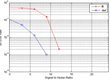
Fig 7: BER Performance for 16-QAM FFT/DWT OFDM System
The number of subcarriers used in OFDM system is 64. The system simulated does not use any channel estimation technique and error estimation or correction capabilities. All of the simulations assume that, channel-state information will not change in one OFDM symbol. To ensure the reliability of the computer simulations, OFDM symbols are generated to obtain each BER value in the simulations.
Simulink model indicated in Fig.5 and Fig.6 is used; QAM modulation is used with a suitable M-ary order. Simulation is carried out for Signal to noise ratio in the range 0 to 20dB and for 16-QAM as a modulation technique.
As a first experiment we have simulated of FFT-OFDM and DWT-OFDM system with 16-QAM modulation. Fig.7 shows the results of the simulation. From the graph it is observed that the performance of DWT-OFDM is superior to FFT-OFDM. In case of FFT-OFDM a BER of 0.0020 is achievable at 12 dB SNR, whereas DWT-OFDM gives BER of 0.0017 at 9 dB SNR. Table.1 gives the numerical results of the simulation for 16-QAM FFT and DWT based OFDM. Table.1 gives the numerical results of the simulation of 16-QAM FFT and DWT-OFDM system.
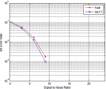
The second experiment is performed to demonstrate the performance of DWT-OFDM for two mother wavelets namely Haar and Biorthogonal which are recommended for DWT-OFDM. Fig. 8 shows the simulation results in terms of BER. From the graph we observe that biorthogonal 1.1 performs better than Haar wavelet. For simple system Haar mother wavelet is recommended which has less complexity in implementation.
Table 1: BER Performance for 16-QAM FFT/DWT OFDM System
SNR(dB) BER of FFT-OFDM BER of DWT-OFDM
0 0.4968 0.1195
6 0.4300 0.0172
9 0.1544 0.0017
Fig 8: BER performance of DWT-OFDM system using Haar and biorthogonal wavelets.
Further investigation is carried out to illustrate the effect of increase in constallations. Here we have simulated 16 QAM and 64 QAM modulation based DWT-OFDM system using bior 1.1 mother wavelet. Fig.9 show the comparison of 16-QAM and 64-QAM based DWT-OFDM. The BER performance of 16-QAM is better than 64-QAM but the difference is marginal.
Fig 9: BER performance of DWT-OFDM system using 16-QAM and 64-QAM for biorthogonal wavelet.
5. Conclusion
This paper presents the Simulink simulation approaches for DWT-OFDM as alternative substitutions for FFT-OFDM. From the analysis and Simulink design simulation we found that the designed simulation model is trustworthy. For DWT-OFDM haar and bior1.1 mother wavelets will be the best choice for implementation.
Acknowledgment
Author would like to thank the Director, Applied Digital Microsystems Pvt. Ltd., Mumbai and Pune Institute of Computer Technology, Pune for all the support and encouragement.
References
[1] M.K.Lakshmanan, Nikookar,“A Review of Wavelets for Digital Wireless Communication”Wireless Personal Communications Vol. 37, Issue: 3-4, pages 387–420, Springer 2006.
[2] M. K. Lakshmanan. Nikookar, “A Review of Wavelets for Digital Wireless Communication”Wireless Personal Communications Vol. 37, Issue: 3-4, pages 387–420, Springer 2006.
[3] Mrs. Veena M. B. Dr. M. N. Shanmukha Swamy, “Performance analysis of DWT based OFDM over FFT based OFDM and implementing on FPGA” International Journal of VLSI design & Communication Systems (VLSICS) Vol.2, No.3, September 2011. [4] Swati Sharma, Sanjeevkumar, “BER Performance Evaluation of FFT-OFDM and DWT-OFDM” International Journal of Network and
Mobile Technologies ISSN 2229-9114 Electronic Version VOL 2 / ISSUE 2 / MAY 2011.
[5] Andre Ken Lee, Ooi, Micheal Drieberg and Varun Jeoti, “DWT based FFT in Practical OFDM Systems”1-4244-0549-1/06/$20.00 ©2006 IEEE.
[6] Marius Oltean, Miranda Nafornita, “Efficient Pulse Shaping and Robust Data Transmission Using Wavelets”1 -4244-0830-X/07/ ©2007 IEEE.
[7] Swati Sharma and Sanjeev Kumar, “BER Performance Evaluation of FFT-OFDM and DWT-OFDM” IJNMT ISSN 2229-9114 Electronic version vol 2/issue 2/ May 2011.I
[8] Mohammed Aboud Kadhim,Widad Ismail, “Implementation of WiMax IEEE802.16d Baseband Transceiver Based Wavelet OFDM on Multi-Core Software-Defined Radio Platform” European Journal of Scientific Research ISSN 1450-216X Vol.42 No.2 (2010), pp.303-313rn
[9] tR.S. Bodhe, S.S. Narkhede, Shirish Joshi, “Design and Implementation of Baseband Processing for Wavelet OFDM”, National Conference e-PGCON 2012, Pune
Authors profile
Rohit Bodhe is currently pursuing his master of engineering degree in Electronics and Telecommunication specialization in Microwave from Pune Institute of Computer Technology, Pune, India. He received B.E from Pune Vidyarthi Griha’s COET, University of Pune, India in 2010. He is currently working as a project intern at Applied Digital Microsystems Pvt.Ltd. Mumbai, India. He has completed project internships in Skylab Systems, Pune, India; Department of Electronics, University of Pune, India; Sunpro
Instruments Pvt.Ltd. Pune, India. His research interest includes
Wireless Communication, OFDM, and Wireless Sensor Networks, RFID, Embedded VLSI.
S.S.Narkhede was born in 1964. Currently, he is working as
Associate Professor, Department of Electronics and Telecommunication, Pune Institute of Computer Technology, Pune, India. He received his Master of Engineering degree (M.E) from
University of Pune, India in 2000. He is a member of MIEEE,