Analysis of Pumphouse RCC Frame Structure for Soil Structure
Interaction
Mr A.S. Thombare*, Prof. V.P. Kumbhar**, Prof. A.H. Kumbhar***
* (B.E. Civil Student, Department of Civil Engineering, Dr. Daulatrao Aher College Of Engineering, Karad, MH **&*** (Assistant Professor, Department of Civil Engineering, Dr. Daulatrao Aher College Of Engineering, Karad,
ABSTRACT
When structure is built on ground some elements of structure are direct contact with soil. When loads are applied on structure internal forces are developed in both the structure as well as in soil. It results in deformation of both the components which are independent to each other. This are called soil structure interaction. The analysis is done by using (Bentley STAAD.Pro V8i Version 2007) software. The analysis carried out been pump house structure R.C.C. frame structure find out shear force Z direction fixed support and fixed but support for different soil. It concluded that soil structure interaction more affected on fixed base. So overcome the effects of the soil structure interaction on the soft soil, it is important to design the structure to standard loading condition and interaction forces. Thus here concluded that pump house building should be design resist the maximum shear force in fixed base.
Keywords- Pump house, shear force, Soil structure interaction, STAAD.Pro V8i, Static analysis.
I.
INTRODUCTION
Soil structure interaction is a challenging multidisciplinary subject which covers several areas of civil engineering. The soil structure interaction problem has it is important feature of structural engineering on soft soils such as nuclear power plants, concrete and earthen dams. Buildings, bridges, tunnels, pump house, and underground structures may also require particular attention to be given to the problems of soil structure interaction. When structure is built on ground some elements of structure are direct contact with soil. When loads are applied on structure internal forces are developed in both the structure as well as in soil. It results in deformation of both the components which are independent to each other. This mutual dependence in is term as interaction.
Every seismic structural response is caused by soil interaction forces by impacting the structure. These forces occur for every structure but not always. They are able to change the soil motion. Present work of the paper find out the shear force Z-direction for fixed base and fixed but support for different soil condition like soft, medium and hard soil for seismic load condition.
II.
LITURATURE REVIEW
Dr. G. Ravi, Dr. H. S. Prasanna, Vinay M. L. Gowda (December 2015) [1] focus on potential effects of SSI o framed structure with shallow foundation resting on clayey soils. This analysis provides results in the form of stresses and bending moment values, deformation, story drift which are realistic values than those provided by analysis.
Bhojegowda V T, Mr. K. G. Subramanya (August 2015) [2] considered that framed structure is to be fixed neglecting the effect of soil and foundation flexibility. It is understand that the study has carried out for building with isolated, mat, pile foundations for different soil conditions like soft, medium, and hard strata in that paper.
Ketan Bajaj, Jitesh T. Chavda, Bhavik M. Vyas (2013) [3] studied the buildings are subjected to different earthquake loading and behaves differently with the types of condition, such as soft, medium and hard soil. Different soil properties can affect seismic waves as they pass through a soil layer. With the change in soil property from hard to medium and from hard to soft the displacement has increased by respectively for flexible base.
Pruthvi Chowdary, Pallavi Ravishankar, neelima Satyam (2014) [4] This paper subjected to study to observe the trends in bending moments, deflection in longitudinal girders and in piles subjected to the given dynamic loading.
Raveesh Bhat, S. A. Warad (2012) [5] performs the non-linear static analysis in a very simple way. In the present study 11 storey RC moment resisting frames are designed by the limit state of design method.
III.
CASESTUDY
It is considered case study of the pump house structure located at Indoli, Karad Taluka on the Tarali River, in Maharashtra State. Masonry dam of capacity 5.85 TMC is under construction on Tarali River near Dangishtewadi Tal. Patan. Total seven numbers of Lift Irrigation Schemes are proposed in Tarali Project of which four L. I. Schemes are proposed on K. T. weirs and three on Koparde Approach Canal. Total area under the project is 14276 Ha of which 5400 Ha area is in tarali valley.
Fig 3.1 Pump House at Indoli
IV. DATA ANALYSIS
4.1 Software Details
The analysis is done by using (Bentley STAAD.Pro V8i Version 2007) software. It is an analysis and design software package for structural engineering. STAAD.Pro V8i is the most popular structural engineering software product for 3D model generation, analysis and multi-material design, for static or dynamic analysis of bridges, containment
structures, embedded structures (tunnels and
culverts), pipe racks, steel, concrete, aluminum or timber buildings, transmission towers, stadiums or any other simple or complex structure.
4.2 Details of R.C.C. Frame
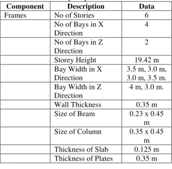
R.C.C. frame buildings 13 x 7 resting on different types of soil in layered soil stratum are considered in the study. The frames are considered with fixed base support and fixed but support represented by layered soil models. Total height of building is 19.42 m. the pump house of building below the ground level is 11.42 m. The beams and columns are modeled as 3D frame element. The geometric properties of frame and material properties of frame adopted in the analysis are presented in table 4.1 and table 4.2
Table 4.1 Geometry Properties of Frame Sections Component Description Data
Frames No of Stories 6
No of Bays in X Direction
4
No of Bays in Z Direction
2
Storey Height 19.42 m
Bay Width in X Direction
3.5 m, 3.0 m, 3.0 m, 3.5 m. Bay Width in Z
Direction
4 m, 3.0 m.
Wall Thickness 0.35 m
Size of Beam 0.23 x 0.45
m
Size of Column 0.35 x 0.45
m
Thickness of Slab 0.125 m
Thickness of Plates 0.35 m
Table 4.2 Material Properties
Component Description Data
Material Concrete M25 grade
Elastic Modulus 2.17184 x 10⁷
Poisson’s Ratio 0.17
Thermal Coefficient
5.5 x 10⁻⁶
Critical Damping 0.05
Shear Modulus 0
Density 23.5615
Weight per Unit Volume
25 KN/m3
Masonry Weight per Unit
Volume
20 KN/m3
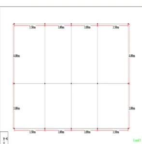
Fig. 4.1 Plan of R.C.C. Frame Structure
The following figure shows the 3D view of R.C.C. frame building.
Fig. 4.2 3D View of R.C.C. Frame Building
4.3 Seismic Parameters
For the SSI analysis using Bureau of Indian Standards in IS 1893 (Part I): 2002 is used for Static and Dynamic analysis. The building is assumed to be situated in Zone IV. Medium, hard and soft are three types of soil upon which structural frames are considered to be resting. The following table is given to Seismic Parameters.
Table 4.3 Seismic Parameters
Sr. No. Parameters Values
1 Zone ( IV) 0.24
2 Response Reduction Factor
(RF) ( SMRF)
5
3 Rock and Soil Site Factor
(SS)
1
4 Type of Structure ( RC
frame building)
1
5 Damping Ratio (DM) 5
6 Period in x Direction (PX) 0.5
7 Period in z direction (PZ) 0.5
8 Importance factor ( I)
( Important Building)
1.5
9 Depth of Foundation ( DT) 11.42 m
4.4 Loads
The load should be calculated by traditional method. The load should b calculated for analyze the model. Following loads are given in table 4.4.
Table 4.4 Loads Types of Loads Value
Dead Load on Roof 4.2 KN/m
Dead Load on Floor 42 KN/m
Live Load on Floor 15 KN/m
Floor Load 15 KN/m2
Wind Load 135 KN
Self Weight Factor 1
Nodal Load 75 KN
4.5 Load Combinations
It is considering the static and dynamic analysis of model using the load combinations and their partial safety factor. Using the Bureau of IS 456-2000 and IS 1893 (part I):2002 both the different combinations of dead load, imposed load, wind load and seismic load as per considered. The table 4.5 shows the IS 456-2000 load combinations and table 4.6 shows the IS 1893 (Part I): 2002 load combinations.
Table 4.5 Loads Combinations of IS 456-2000 Load
Combin ation
Limit State of Collapse
Limit State of Serviceability
DL IL WL DL IL WL
DL + IL 1.5 1.5 1.0 1.0 1.0 -
DL + WL
1.5 or 0.9
- 1.5 1.0 - 1.0
DL + IL + WL
1.2 1.2 1.2 1.0 0.8 0.8
Table 4.6 Load Combinations of IS 1893 (Part I): 2002
Load Combinati
on
Limit state of RC Structure
DL IL EL
DL + IL + EL
1. 1.2 1.2
DL + IL –
EL
1.2 1.2 1.2
DL + EL 1.5 - 1.5
DL – EL 1.5 - 1.5
DL + EL 0.9 - 1.5
DL – EL 0.9 - 1.5
IV.
RESULTS AND DISCUSSIONS
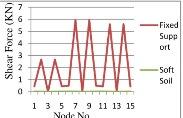
From the above analysis shear force Z direction results along the fixed support and fixed but support for different soil soft, medium and hard soil. Shear force in Z direction for bottom support results should be found out governing load case seismic load case only. The following graph shows the shear force in Z direction of fixed support and fixed but support for different soil.
Fig. 5.1 Shear force of Fixed Support and Soft Soil
Fig. 5.2 Shear force of Fixed Support and Medium Soil
Fig. 5.3 Shear force of Fixed Support and Hard Soil
Fig. 5.4 Shear force of Fixed Support and Fixed but Support
V.
CONCLUSION
Bending moment Z direction at bottom
minimum in fixed support is 22.21 KN-m.
Fixed but support maximum bending moment
for soft soil is (152.73 KN-m) medium soil (121.01 KN-m) and soft soil (93.68 KN-m).
From the above analysis soil structure more
affected on soft soil. So overcome the effects of the soil structure interaction on the soft soil, it is important to design the structure to standard loading condition and interaction forces.
REFERENCES
[1]. Dr. G. Ravi, Dr. H. S. Prasanna, Vinay M.
L. Gowda, December 2015, ‘Soil structure
interaction for RCC framed structure – A
case study’, College of Engineering, Pune,
India.
[2]. V. T. Bhojegowda, Mr. K. G. Subramanya,
August 2015, ‘Soil structure interaction of 0 1 2 3 4 5 6 7
1 3 5 7 9 11 13 15
Fixed Supp ort Soft Soil
S
he
ar F
or
ce
(K
N)
Node No.
0 1 2 3 4 5 6 71 3 5 7 9 11 13 15
Fixed Support Medium Soil
S
he
ar F
or
ce
(K
N)
Node No.
0 1 2 3 4 5 6 71 3 5 7 9 11 13 15
Fixed Suppo rt Hard Soil
S
he
ar F
or
ce
(K
N)
Node No.
0 1 2 3 4 5 6 71 3 5 7 9 11 13 15
framed structure supported on different
types of foundation’, Civil Engineering
Department, Government S.K.S.J.T.I, K.R
Circle, Bengaluru, Karnataka, India,
International Research Journal of
Engineering and Technology (IRJET), pp 651-660.
[3]. Ketan Bajaj, Jitesh T. Chavda, Bhavik M.
Vyas, December 2013, ‘Seismic behavior of
buildings on different types of soil’, PG
Student, National Institute of Technology, pp 1-6.
[4]. Pruthvi Chowdary, Pallavi Ravishankar,
Neelima Satyam, December 2014, ‘Soil
structure interaction analysis for integral
abutment bridge system’, Proceedings of Indian Geotechnical Conference IGC- 2014,
Centre of Earthquake Engineering,
International Institute of Information
Technology, Hyderabad – 500 032, India.
[5]. Raveesh Bhat, S. A. Warad, 2012, ‘Seismic evalution of RC building considering soil
structure interaction’, PG, Scholar,
Department of Civil Engineering, PGH, CET bijapur, India.