Fingerprint Recognition Using Global and Local
Structures
Kalyani Mali,
Department of Computer Science & Engineering, University of Kalyani,
Kalyani, West Bengal, India
Samayita Bhattacharya,
Department of Computer Science & Engineering, University of Kalyani,
Kalyani, West Bengal, India
Abstract: - Biometrics is one of the biggest tendencies in human identification. The fingerprint is the most widely used biometric. However considering the automatic fingerprint recognition a completely solved problem is a common mistake. The global level structures consist of many ridges to form some specific shape like arch, loop, and whorl. Local level structures are called minutiae, which further classified as either endpoints or bifurcations. Either of which can be used to identify the fingerprint, our approach uses both methods.
Key-words: - Fingerprint, Global Structure, Local Structure, Average Gradient, Core, Delta, Point Orientation, Singular Point, Directional Field, Ridge, Valley, Bifurcation, Ridge Ending, Minutiae. 1. Introduction
Fingerprints are the graphical flow-like ridges present on human fingers. Finger ridge configurations do not change throughout the life of an individual except due to accidents such as bruises and cuts on the fingertips. This property makes fingerprints a very attractive biometric identifier. Fingerprint-based personal identification has been used for a very long time [1]. Owning to their distinctiveness, stability durability, and convenience, fingerprints are the most widely used biometric features.
The fingerprint is a duplicate of a fingertip epidermis when a person touches a smooth surface, the fingertip epidermis characteristic transferred to the surface. The pattern of the ridges and valleys on the human fingertips forms the fingerprint images. Analyzing this pattern at different levels reveals different types of features that are, global feature and local feature. Global features shape a special pattern of ridge and valleys, called singularities or Singular Point (SP) and the important points are the core and the delta. The core defined as the most point on the inner most ridges and a delta defined as the centre point where three different directions flows meet. The SP provides important information for fingerprint classification, fingerprint matching and fingerprint alignment.
Local features so-called minutiae are an important feature for fingerprint matching.
Fingerprint patterns are full of ridges and valleys. The information of the ridge structures can be treated as three levels. At the coarse level, the number and the relative positions of singular points, including cores and deltas, are concerned for classification. At the fine level, the minutiae, a group of ridge endings and bifurcations, are used as the features for matching. Between the above two levels, the middle level also contains important information, including local ridge orientation (LRO) and local ridge frequency (LRF). Conventionally, only the structures of LROs are used to find the singular points for classification or to enhance ridge structures for minutiae extraction.
Although other approaches are possible, like, for instance, the hashing technique in the minutiae domain, the first step in an identification system is often continuous classification of fingerprints. This reduces the partition of the database to be searched for matches. To facilitate high-performance classification, algorithms for accurate singular-point estimation are needed. Singular point detection is a critical process for both fingerprint matching and fingerprint classification. The process of singular points detection must be fast and robust; otherwise, the performance of the whole fingerprint recognition system would be influenced heavily.
In high level fingerprint classification algorithms, extracting the number and precise location of singular points (SP), namely core and delta points are of great importance. According to the number and location of these robust characteristics, fingerprints can be classified in to five main groups; arch, tented arch, right loop, left loop, and whorl.
Using high-level classification process can efficiently reduces the search area in large fingerprint databases and therefore speeds up the subsequent matching algorithm. There are four main approaches to allocate SPs [24].
Methods based on mathematical model representation of fingerprint.
Because of the complexity of fingerprint patterns, representation of an accurate model for these images is a difficult task that can not be achieved this type of models [25], [26].
In these methods although the usage of histogram has reduced the noise effect, however they cannot adapt themselves to different image characteristics [28].
Methods based on different frequency transforms like Fourier Transform, Gabor Transform.
These methods are not efficient enough because of working in the frequency domain. But some have claimed to obtain fair results [29].
Methods based on fingerprint structures.
These are usually well applied approaches, which have been tested successfully on large databases [21], [27], [31].
Some approaches combine several types of the above mentioned methods and make a new combined system [30].
Singular points detection is the most challenging and important process in biometrics fingerprint verification and identification systems. Singular points are used for fingerprint classification, fingerprint matching and fingerprint alignment.
Nowadays, most automatic fingerprint identification systems (AFIS) are based on matching minutiae, which are local ridge characteristics in the fingerprint pattern. The two most prominent minutiae types are ridge ending and ridge bifurcation. Based on the features that the matching algorithms use, fingerprint matching can be classified into image-based and graph-based matching.
Image-based matching [2] uses the entire gray scale fingerprint image as a template to match against input fingerprint images. The primary shortcoming of this method is that matching may be seriously affected by some factors such as contrast variation, image quality variation, and distortion, which are inherent properties of fingerprint images. The reason for such limitation lies in the fact that gray scale values of a fingerprint image are not stable features.
Graph-based matching [5], [8] represents the minutiae in the form of graphs. The high computational complexity of graph matching hinders its implementation. To reduce the computational complexity, matching the minutiae sets of template and input fingerprint images can be done with point pattern matching. Several point pattern matching algorithms have been proposed and commented in the literature [3], [4], [9], [11], [12]. Fingerprint system can be separated into two categories Verification and Identification.
Verification system authenticates a person’s identity by comparing the captured biometric characteristic with its own biometric template(s) pre-stored in the system. It conducts one-to-one comparison to determine whether the identity claimed by the individual is true. A verification system either rejects or accepts the submitted claim of identity.
Identification system recognizes an individual by searching the entire template database for a match. It conducts one-to-many comparisons to establish the identity of the individual. In an identification system, the system establishes a subject’s identity (or fails if the subject is not enrolled in the system database) without the subject having to claim an identity.
In order to implement a successful algorithm of this nature, it is necessary to understand the topology of a fingerprint. A fingerprint consists of many ridges and valleys that run next to each other, ridges are shown in black and valleys are shown in white.
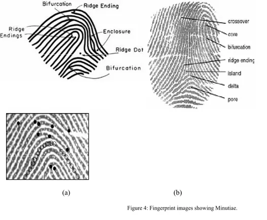
The ridges bend in such ways as to form both local and global structures; either of which can be used to identify the fingerprint. The global level structures consist of many ridges that form arches, loops, whirls and other more detailed classifications, as shown in Figure 5. Global features shape a special pattern of ridge and valleys. On the other hand, the local level structures, called minutiae, are further classified as either endpoints or bifurcations. Minutiae are also given an associated position and direction, as shown in Figure 1 and in Figure 4. Our procedure is mainly based on minutiae, as well as on global level structure for finding a reference point by which alignment of two template is to be accomplished.
In addition, scanned fingerprints are subject to distortions that must also be taken into account including rotation, translation, non-linear scaling and extraneous or missing minutiae between matching fingerprints. This creates difficulty in the matching phase because it causes the minutiae to differ between two identical fingerprints.
Figure 1: Types of fingerprint minutiae and their respective directions. (a) an endpoint, (b) a bifurcation.
Figure 2: (a) Original fingerprint. (b) Detected minutiae.
1. Background
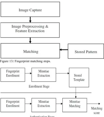
Most approaches to recognizing a fingerprint involve five basic stages: (i) acquisition, where the image is obtained from hardware or a file; (ii) pre-processing, which may include thinning, noise reduction, image enhancements and error correction; (iii) structural extraction, where global and local structures may be found; (iv) post-processing, where the structures are converted into a more useful format; (v) and then matching, where fingerprints are compared against a database. These stages are shown in Figure 3.
3. Approach to Extract Singular Point
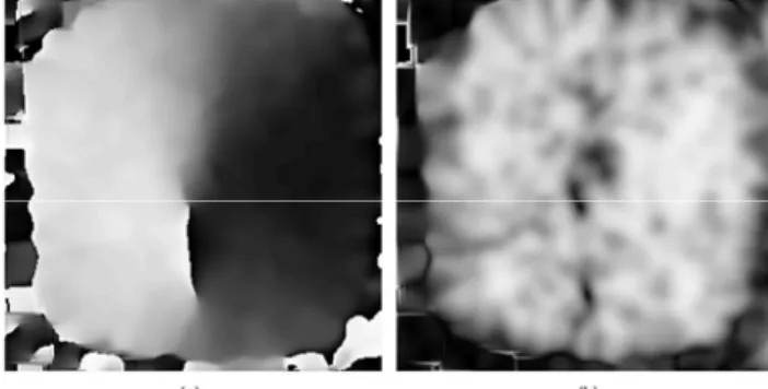
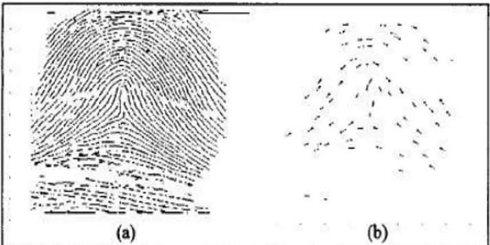
In Fig. 6a, a fingerprint is depicted. The information carrying features in a fingerprint are the line structures, called ridges and valleys. In this figure, the ridges are black and the valleys are white. It is possible to identify two levels of detail in a fingerprint. The directional field (DF), shown in Fig. 6b, describes the coarse structure, or basic shape, of a fingerprint. It is defined as the local orientation of the ridge valley structures.
The DF is, in principle, perpendicular to the gradients. However, the gradients are orientations at pixel scale, while the DF describes the orientation of the ridge-valley structures, which is a much coarser scale. Therefore, the DF can be derived from the gradients by performing some averaging operation on the gradients, involving pixels in some neighborhood [13].
Various methods used to estimate the DF from a fingerprint are known from literature. They include matched-filter approaches [9], [14], [15], methods based on the high-frequency power in three dimensions [16], 2- dimensional spectral estimation methods [15], and micropatterns that can be considered binary gradients [10]. These approaches do not provide as much accuracy as gradient based methods, mainly because of the limited number of fixed possible orientations. This is especially important when using the DF for tasks like tracing flow lines. The gradient-based method was introduced in [7] and adopted by many researchers, see, e.g., [9], [17], [18], [20]. The elementary orientations in the image are given by the gradient vector [Gx(x,y) Gy(x,y)]T, which is defined as:
Gx x, y
Gy x, y = sign (Gx) I(x,y)
= sign (∂I(x,y)/∂x) ∂I x, y / ∂x
∂I x, y / ∂y (1)
where I(x,y) represents the gray-scale image.
The first element of the gradient vector has been chosen to always be positive. The reason for this choice is that in the DF, which is perpendicular to the gradient, opposite directions indicate equivalent orientations.
(a) (b) (c)
Arch
Tented Arch
Left Loop Right Loop Whorl
Figure 5: Fingerprint Patterns.
Figure 6. Examples of a fingerprint, its directional field and its singular points: (a) fingerprint, (b) directional field, and (c) singular points.
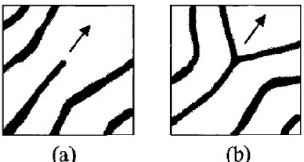
Next phase is the extraction of the SPs, which are the points in a fingerprint where the DF is discontinuous. In Fig. 7, two segments of the fingerprint of Fig. 6 are shown, one containing a core and one containing a delta. The SPs are somewhere in the center of the segments. However, they cannot be located more accurately than within the width of one ridge-valley structure in the gray-value fingerprint.
Figure 7. Segments of a fingerprint that contain a singular point. (a) Core and (b) delta.
4. Approach to Extract Minutia
The minutiae provide the details of the ridge-valley structures, like ridge-endings and bifurcations. Minutiae are, for instance, used for fingerprint matching, which is a one-to-one comparison of two fingerprints. In our approach currently we have used one to one pixel matching for minutia extraction.
5.Image Acquisition
The first stage of any vision system is the image acquisition stage. Image acquisition is hardware dependent. A number of methods are used to acquire fingerprints. Among them, the inked impression method remains the most popular one. Inkless fingerprint scanners are also present eliminating the intermediate digitization process [6].
The basic two-dimensional image is a monochrome (greyscale) image which has been digitized. Describe image as a two-dimensional light intensity function f(x,y) where x and y are spatial coordinates and the value of f at any point (x, y) is proportional to the brightness or grey value of the image at that point.
A digitized image is one where
spatial and greyscale values have been made discrete
intensity measured across a regularly spaced grid in x and y directions intensities sampled to 8 bits (256 values)
The method chosen for acquisition of a fingerprint image depends on many different factors, including the cost and reliability of an input device.
6. Pre-processing
This is an essential part of fingerprint recognition. In this step the image is made ready for the actual matching. The input of this phase is the original fingerprint image and the final output of this step is the minutiae of that image.
Our proposed algorithm for pre-processing is as followed.
6.1. Fingerprint image enhancement
Three types of degradations affect the quality of the fingerprint image. The ridges get some gaps; parallel ridges connected due to noise and natural effect to the finger like cuts, wrinkles and injuries. The Fingerprint enhancement is anticipated to improve the contrast between ridges and valleys and reduce noises in the fingerprint images.
High quality fingerprint image is very important for fingerprint verification or identification to work properly. In real life, the quality of the fingerprint image is affected by noise like smudgy area created by over-inked area, breaks in ridges created by under-inked area, changing the positional characteristics of fingerprint features due to skin resilient in nature, dry skin leads to fragmented and low contrast ridges, wounds may cause ridge discontinuities and sweat on fingerprints also leads to smudge marks and connects parallel ridges.
6.2.Noise reduction
Noise is an unwanted perturbation to a wanted signal. Image noise is generally regarded as an undesirable by-product of image capture. Noise reduction is the process of removing noise from a picture (here it is the fingerprint image).
We have checked and used different types of filtering methods like median filter, global and adaptive thresholding to reduce the noise [23].
6.3. Image normalization
The objective of this stage is to decrease the dynamic range of the gray scale between ridges and valleys of the image in order to facilitate the processing of the following stages.
The processing of fingerprint normalization can reduce the variance in gray-level values along ridges and valleys by means of adjust the gray-level values to the predefined constant mean and variance. And normalization can remove the influences of sensor noise and gray-level deformation.
Let I(i,j) denote the gray-level value of pixel (i,j) in acquired image, the size of fingerprint image is m x n , M and V are the estimated mean and variance of input fingerprint image, respectively, and N(i, j) denote the normalized gray-level value at pixel (i, j). The normalized image is defined as follows:
N(i,j)=
M₀ V₀V I i, j M I i, j M , ,
M₀ V₀V I i, j M I i, j M ,
(2)
6.4.Selection of the interest region
Since the image has background noise, the algorithm may generate minutiae outside the fingerprint area. So selection of the interest area is one important step.
This step is carried in few phases: (a) divide the image into blocks, (b) find the average gradient of each block, (c) find the position of the image where the average gradient of two successive blocks has the zero crossing and the maximum absolute value, (d) take the approximate middle point of these two particular blocks as the reference point, (e) crop out a suitable region around this reference point.
Equation No. 1 is used to calculate the elementary orientations in the image by the gradient vector.
Figure 9. Gray-scale coded directional field and coherence. (a) Directional field and (b) coherence.
Most authors process fingerprints block-wise for calculating DF [4], [21]. This means that the directional field is not calculated for all pixels individually. Instead, the average DF is calculated in blocks of, for instance, in our approach we used 8 by 8 pixel block.
We are using gradient calculation method to calculate the reference point. The reference point is being calculated by calculating the average gradient of 8 x 8 pixel block of the fingerprint image [7], [10].
6.5.Binarization
In the pre-processing stage, the image is converted from greyscale to black and white. This is done by calculating the average background intensity and subtracting this value from the greyscale image. Next greyscale threshold (basic global and adaptive thresholding) is calculated sopixels above this value become black, and the ones below become white [23].
Figure 10: (a) Original Fingerprint, (b) Binarized Fingerprint.
6.6.Thinning
Next the ridges must be thinned to a width of one-pixel. In this step two consecutive fast parallel thinning algorithms are applied, in order to reduce to a single pixel the width of the ridges in the binary image. These operations are necessary to simplify the subsequent structural analysis of the image for the extraction of the fingerprint minutiae. The thinning must be performed without modifying the original ridge structure of the image. During this process, the algorithms cannot miscalculate beginnings, endings and or bifurcation of the ridges, neither ridges can be broken.
Figure 11: (a) Binarized Fingerprint , (b) Image after thinning.
6.7.Minutiae extraction
In the last stage, the minutiae from the thinned image are extracted, obtaining accordingly the fingerprint biometric pattern. This process involves the determination of: i) whether a pixel, belongs to a ridge or not and, ii) if so,whether it is a bifurcation, a beginning or an ending point, obtaining thus a group of candidate minutiae. Next, all points at the border of the interest region are removed.
6.8.Cancellation of improper minutiae
This is an important step of minutiae based fingerprint reorganization system. In this step, the improper minutia which are mainly result of spurious noise of input image, are cancelled.
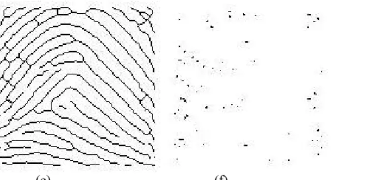
Figure 12: (a) Image after thinning and imperfection removal. (b) Minutiae pattern
7. Matching
Matching is a key operation in the current fingerprint identification system. One of the most important objectives of fingerprint systems is to achieve a high reliability in comparing the input pattern with respect to the database pattern. Reliably matching fingerprint images is an extremely difficult problem, mainly due to the large variability in different impressions of the same finger (i.e., large intra-class variations). The main factors responsible for the intra-class variations are: displacement, rotation, partial overlap, non-linear distortion, variable pressure, changing skin condition, noise, and feature extraction errors. Therefore, fingerprints from the same finger may sometimes look quite different whereas fingerprints from different fingers may appear quite similar.
Figure 13: Fingerprint matching steps.
Figure 14: Fingerprint authentication steps.
8. Experimental result
This Fingerprint Recognition System works for two types of matching.
One fingerprint image is fed into the system to check (a) whether it belongs to a particular database and if so then for which entry/entries of the database (Identification), or (b) if it confirms to be fingerprint of a particular person (Verification).
This project further automatically adds new fingerprint to the database, if the fingerprint to be matched does not exist in the database previously.
Our proposed method is based on pixel to pixel matching for minutia. In this method the fingerprint image is being cropped with respect to a particular point (reference point) of the image; this cropped area is called the region of interest. In our system, the region of interest is taken as the 68 x 68 pixel block around the reference point.
At first we removed the noise by median filtering followed by basic adaptive global thresholding. We have processed fingerprints block-wise for calculating DF. This means that the directional field is not calculated for all pixels individually. Instead, the average DF is calculated in blocks of, for instance, in our approach we used 8 by 8 pixel block.
We are using gradient calculation method to calculate the reference point. The reference point is being calculated by calculating the average gradient of 8 x 8 pixel block of the fingerprint image. For the maximum value of the average gradient of two successive blocks that has the zero crossing, the middle point of the successive blocks is taken as the reference point.
(a) (b)
Figure 15: Original picture and the calculated region to be cropped.
(a) (b) (c) Figure 16: (a) original picture, (b) cropped region, (c) extracted minutiae
Here we have kept a threshold value for checking the number of minutiae matched. By changing the threshold value we get different rate of acceptance and rejection.
Figure 17(b) and Figure 17(c) are two distorted images obtained from Figure 17(a); (b) is accepted but (c) is not because of its high degradation.
(a) (b) (c)
Figure 17: (a) fingerprint to be matched with, (b) accepted little distorted image, (c) rejected more distorted image.
(a) (b)
(e) (f)
Figure 18: Result of pre-processing steps. (a) original image, (b) image after noise reduction and normalization, (c) region of interest, (d) cropped image, (e) thinned image, (f) extracted minutia.
9. Discussion
There have been many algorithms developed for extraction of both local and global structures. Most algorithms found in the literature are somewhat difficult to implement and use a rather heuristic approach.
Here in our proposed method, we have used 8 x 8 pixel block for gradient calculation. And we have taken 68 x 68 pixel values around the reference point, as we used the method on dummy database, for larger database having larger fingerprint image sizes, the pixel values can be suitably changed.
For noisy database, we have seen that the 4 x 4 pixel block for gradient calculation is giving us a better result. It is also seen that this gradient approach is not suitable for all kinds of fingerprints, and further attributes are also required in order to accomplish the matching.
In our future work, we are trying to solve this shortcoming.
10. Future Scope
In this paper, minutiae extraction based fingerprint detection was applied with gradient detection as a step, to find the reference point.
The singular point detection method can be applied as a step to cluster the fingerprint images into five major groups (i.e. arch, tented-arch, left loop, right loop, whorl), and then minutiae extraction based method can be applied on the clusters to achieve a hierarchical fingerprint detection algorithm. We are trying to incorporate this approach in future.
Clustering the fingerprint images in five major groups is quite easy if it is done manually by visual checking, but implementing an automated system for this is quite a hard job.
We are also investigating different soft computing approaches for calculating the reference point, as well as minutiae, for better result.
This method is not yet generalised, finer approach will be taken in future. If the image is not much noisy, it calculates the reference point to be the singular point.
In future we have to search for and apply position invariant features. Also our method is yet to be tested on large database.
11. Conclusion
The reliability of any automatic fingerprint recognition system strongly relies on the precision obtained in the extraction process. Extraction of appropriate features is one of the most important tasks for a recognition system.
References
[1] H. C. Lee and R. E. Gaensslen, Eds., Advances in Fingerprint Technology. New York: Elsevier, 1991.
[2] R. Bahuguna, “Fingerprint verification using hologram matched filterings,” presented at the 8th Meeting Biometric Consortium, San Jose, CA, Jun. 1996.
[3] A. Ranade and A. Rosenfeld, “Point pattern matching by relaxation,” Pattern Recognit., vol. 12, no. 2, pp. 269–275, 1993.
[4] A. Jain, L. Hong and R. Bolle, “On-Line Fingerprint Verification“, IEEE Trans. Pattern Analysis and Machine Intelligence, Vol. 19, No.4, pp. 302-3 14, Apr. 1997.
[5] S. Gold and A. Rangarajan, “A graduated assignment algorithm for graph matching,” IEEE Trans. Pattern Anal. Mach. Intell., vol. 18, no. 4, pp. 377–388, Apr. 1996.
[6] Image Digitization Process by Dorothy VanDeCarr
[7] M. Kass and A. Witkin, ªAnalyzing Oriented Patterns,º Computer Vision, Graphics, and Image Processing, vol. 37, no. 3, pp. 362-385, Mar. 1987.
[8] D. K. Isenor and S. G. Zaky, “Fingerprint identification using graph matching,” Pattern Recognit., vol. 19, no. 2, pp. 113–122, 1986. [9] A. K. Jain, L. Hong, S. Pankanti, and R. Bolle, “An identity authentication system using fingerprints,” Proc. IEEE, vol. 85, no. 9, pp.
[11] A. Rao, A Taxonomy for Texture Description and Identification. New York: Springer-Verlag, 1990. 1110 IEEE TRANSACTIONS ON IMAGE PROCESSING, VOL. 15, NO. 5, MAY 2006.
[12] C. Studholme, D. L. G. Hill, and D. J. Hawkes, “An overlap invariant entropy measure of 3D medical image alignment,” Pattern Recognit., vol. 32, no. 1, pp. 71–86, 1999.
[13] D. Maio, D. Maltoni, R. Cappelli, J.L. Wayman, and A.K. Jain, ªFVC2000: Fingerprint Verification Competition,º Biolab internal report, Univ. of Bologna, Italy, Sept. 2000, available from http:// bias.csr.unibo.it/fvc2000/.
[14] G.A. Drets and H.G. LiljenstroÈm, ªFingerprint Subclassification: A Neural Network Approach,º Intelligent Biometric Techniques in Fingerprint and Face Recognition, L.C. Jain, U. Halici, I. Hayashi, S.B. Lee, and S. Tsutsui, eds., pp. 109-134, Boca Raton, Fla.: CRC Press, 1999.
[15] C.L. Wilson, G.T. Candela, and C.I. Watson, ªNeural Network Fingerprint Classification,º J. Artificial Neural Networks, vol. 1, no. 2, pp. 203-228, 1994.
[16] L. O'Gorman and J.V. Nickerson, ªAn Approach to Fingerprint Filter Design,º Pattern Recognition, vol. 22, no. 1, pp. 29-38, 1989. [17] A.R. Rao and R.C. Jain, ªComputerized Flow Field Analysis: Oriented Texture Fields,º IEEE Trans. Pattern Analysis and Machine
Intelligence, vol. 14, no. 7, pp. 693-709, July 1992.
[18] N. Ratha, S. Chen, and A. Jain, ªAdaptive Flow Orientation Based Feature Extraction in Fingerprint Images,º Pattern Recognition, vol. 28, pp. 1657-1672, Nov. 1995.
[19] P. Perona, ªOrientation Diffusions,º IEEE Trans. Image Processing, vol. 7, no. 3, pp. 457-467, Mar. 1998. [20] T. Lindeberg, Scale-Space Theory in Computer Vision. Boston: Kluwer Academic Publishers, 1994. [21] K. Karu and A.K. Jain, ªFingerprint Classification,º Pattern Recognition, vol. 29, no. 3, pp. 389-404, 1996. [22] M. Kawagoe and A. Tojo, ªFingerprint Pattern Classification,º Pattern Recognition, vol. 17, no. 3, pp. 295-303, 1984. [23] Rafeal C. Gonzalez, Richard E. Woods, “Digital Image Processing,” Pearson Education Asia, 2002.
[24] A. K. Jain, S. Prabhakar and L. Hong, A Multichannel Approach to Fingerprint Classification, IEEE Transactions on Pattern Analysis and Machine Intelligence 21 (4), (April 1999) 348-358
[25] B. G. Sherlock and D. M. Monro, A Model for Interpreting Fingerprint Topology, Pattern Recognition 26 (7) (1993) 1047-1055. [26] P. R. Vizcaya and L. A. Gerhardt, A Nonlinear Orientation Model for Global Description of Fingerprints, Pattern Recognition 29 (7)
(1996) 1221-1231.
[27] N. K. Ratha, K. Karu, S. Chen and A. K. Jain, A Real Time Matching System for Large Fingerprint Databases, IEEE Transactions on
Pattern Analysis and Machine Intelligence 18 (8) (August 1996) 800-813
[28] V. S. Srinivasan and N. N. Murthy, Detection of Singular Points In Fingerprint Images, Pattern Recognition 25 (2) (1992) 139-153 [29] A. P. Fitz and R. J. Green, Fingerprint Classification Using a Hexagonal Fast Fourier Transform, Pattern Recognition 29 (10) (1996)
1587-1597
[30] G. T. Candela, P. J. Grother, C. I. Watson, R. A. Wilkinson, C. L. Wilson, PCASYS : A Pattern-Level Classification Automation System for Fingerprints, U.S. DEPARTMENT of COMMERCE Technology Administration, National Institute of Standards and
Technology (NIST). Advanced Systems Division, Computer Systems Laboratory, Gaithersburg, MD 20899, (August 1995)
[31] B. H. Choi et al., Core Based Fingerprint Image Classifcation, ICPR'2000'S proceeding, 2 (2000) 859-862
[32] S. Kasaei, M. R. Rahimi, E. Pakbaznia, A Multi Stage Approach to Fingerprint Classification, CEE'2001'S proceeding 14.1-14.8
AUTHORS PROFILE
Kalyani Mali received B Tech and M Tech Degree in 1987 and 1989 from University of Calcutta, India, and PhD degree in Computer Science and Engineering from Jadavpur University, Kolkata, India in 2005. She joined the faculty of Department of Computer Science and Engineering, University of Kalyani in 1992. She currently holds the rank of associate professor. Her current research interests include pattern recognition, image processing, data mining and soft computing.