Image Compression Algorithms for Fingerprint System
Preeti PathakCSE Department, Faculty of Engineering, JBKP, Faridabad, Haryana,121001, India
Abstract
Fingerprint-which have been used for about 100 years are the oldest biometric signs of identity. Humans have used fingerprints for personal identification for centuries and the validity of fingerprint identification has been well established. In fact, fingerprint technology is so common in Human Identification that it has almost become the synonym of biometrics. Fingerprints are believed to be unique across individuals and across fingers of same individual. Even identical twins having similar DNA, are believed to have different fingerprints. The analysis of fingerprints for matching purposes generally requires the comparison of several features of the print pattern. These include patterns, which are aggregate characteristics of ridges, and minutia points, which are unique features found within the patterns. is also necessary to know the structure and properties of human skin in order to successfully employ some of the imaging technologies. A major approach for fingerprint recognition today is to extract minutiae from fingerprint images and to perform fingerprint matching based on the number of corresponding minutiae pairings. One of the most difficult problems in fingerprint recognition has been that the recognition performance is significantly influenced by fingertip surface condition, which may vary depending on environmental or personal causes. Addressing this problem this paper propose some extra features that can be used to strengthen the present approaches followed in developing Fingerprint recognition system. To increase security and accuracy we can use Infrared technique and technique to assign a score value to each of extracted minutiae.
Key Terms– Biometric, Minutiae, Binarization, Thinning,
Median Filter.
1. Introduction
Biometric authentication has been receiving extensive attention over the past decade with increasing demands in automated personal identification . Biometric is to identify individuals using physiological or behavioral characteristics, such as fingerprint, face, iris, retina, palm-print, etc. Among all the biometric techniques, fingerprint recognition [1] is the most popular method and is successfully used in many applications. Typical fingerprint recognition methods employ feature-based image matching, where minutiae (i.e., ridge ending and ridge bifurcation) are extracted from the registered fingerprint image and the input fingerprint image, and the number of corresponding minutiae pairings between the two images is used to recognize a valid fingerprint image [1].The feature-based matching provides an effective way of identification for majority of people.The
minutiae based automatic identification technique first locates the minutiae point and matches their relative placement in a given finger and the stored template, shown in figure 1.
Fig. 1: Fingerprint Recognition System
The fingerprint image may be obtained from a thumb pad fingerprint scanner device scanning at 500 dpi [2] . A good quality fingerprint contains between 60 and 80 minutiae, but different fingerprint have different number of minutiae. A fingerprint image essentially consists of a set of minutiae on the plane. Minutiae are the terminations and bifurcations of ridge lines in a fingerprint image. In order to extract these minutiae, we have to undergo the operation linearization followed by the process of thining. Thus, the set minutiae those are well defined and more prominent then the rest are given higher relevance and importance in the process of minutiae matching.
Fig.2 : Terminations and bifurcations of ridge lines in a fingerprint image
2. System Architecture
1. User Interface (with Infrared Sensor)
2. System Database
3. Enrollment Module
4. Authentication Module
Fig 3 : System Architecture
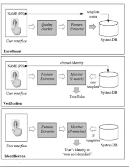
The user interface provides mechanisms for a user to indicate his/her identity and input his/her fingerprints into the system. Here along with finger print scanner the Infrared Sensor will be used. The system database consists of a collection of records, each of which corresponds to an authorized person that has access to the system. Each record contains the following fields which are used for authentication purpose:
User name of the person ,
Minutiae templates of the person’s fingerprint, and other information (e.g., specific user privileges). Alongwith thermal parameter.
The task of enrollment module is to enroll persons and their fingerprints into the system database. When the fingerprint images and user name of a person to be enrolled are fed to the enrollment module, a minutiae extraction algorithm is first applied to the fingerprint images and the minutiae patterns are extracted. A quality checking algorithm is used to ensure that the records in the system database only consist of fingerprints of good quality, in which a significant number (default value is 25) of genuine minutiae may be detected. If a fingerprint image is of poor quality, it is enhanced to improve the clarity of ridge/vally structures and mask out all
the regions that can not be reliable recovered. The enhanced fingerprint image is fed to the minutiae extractor again. The task of authentication module is to authenticate the identity of the person who intends to access the system. The person to be authenticated indicates his / her identity and places his / her finger on the fingerprint scanner ; a digital image of his her fingerprint is captured ; minutiae pattern is extracted from the captured fingerprint image and fed to a matching algorithms which matches it against the person’s minutiae templates stored in the system database to establish the identity To increase security and accuracy we can use Infrared technique and technique to assign a score value to each of extracted minutiae.
Fig. 4: Block diagrams of Enrollment ,Verification, Identification Task
3. Development of proposed system
Proposed system consist of following sub modules -
3.1 Normalization
By normalizing an image, the colors of the image are spread evenly throughout the gray scale. A normalized image is much easier to compare with other images, and the quality of the image is easier determined.
Normalization is a pixel-wise operation that does not change the clarity of the ridge and valley structures . Normalization reduces the variations in gray level values along ridges and valleys, which facilitates the subsequent processing steps.
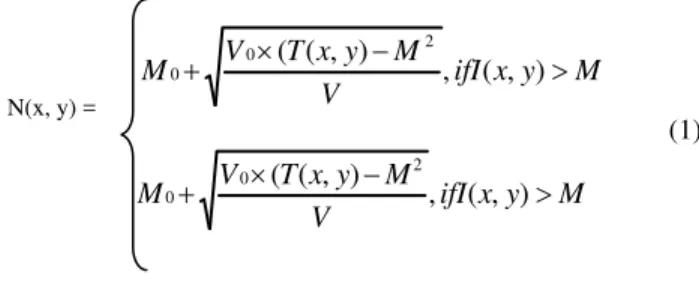
Let I(x; y) denote the grayscale value at pixel (x; y), M and
V, the estimated mean and variance of grayscale values in this 64 X 64 window, respectively, and N(x; y), the normalized grayscale value at pixel (x; y). For all the Pixels in the window, the normalized image is defined as:
M y x ifI V
M y x T V
M ( ( , ) , ( , )
2 0
0
(1)
ifI x y M
V M y x T V
M ( ( , ) , ( , )
2 0
0
In Eq. (1) , M0 and V0 are the desired mean and variance
Values , respectively. Normalization is a pixel-wise Operation and does not change the clarity of the ridge and Valley structures . For our experiments, we set the values of
both M0 and V0 to 100. The values of M0 and V0 should
be the same across all the training and test sets [7].
3.2 Median Filter
In image processing it is usually necessary to perform high degree of noise reduction in an image before performing higher-level processing steps, such as edge detection. The median filter is a non-linear digital filtering technique, often used to remove noise from images or other signals. The idea is to examine a sample of the input and decide if it is representative of the signal. This is performed using a window consisting of an odd number of samples. The values in the window are sorted into numerical order; the median value, the sample in the center of the window, is selected as the output. The oldest sample is discarded, a new sample acquired, and the calculation repeats.
Median filtering is a common step in image processing. It is particularly useful to reduce speckle noise and salt and pepper noise. Its edge-preserving nature makes it useful in cases where edge blurring is undesirable.
The median filter is also a spatial filter, but it replaces the center value in the window with the median of all the pixel values in the window. The kernel is usually square but can be any shape. An example of median filtering of a single 3x3 window of values is shown below.
Unfiltered values 6 2 0 3 97 4 19 3 10
In order: 0, 2, 3, 3, 4, 6, 10, 15, 97
Median filtered
* * * * 4 * * * *
Center value (previously 97) is replaced by the median of all nine values. Note that for the first (top) example, the median filter would also return a value of 5, since the ordered values are 1, 2, 3, 4, 5, 6, 7, 8, 9. For the second (bottom) example, though, the mean filter returns the value 16 since the sum of the nine values in the window is 144 and 144 / 9 = 16. This illustrates one of the celebrated features of the median filter: its ability to remove 'impulse' noise (outlying values, either high or low). The median filter is also widely claimed to be 'edge-preserving' since it theoretically preserves step edges without blurring. However, in the presence of noise it does blur edges in images slightly.
Median filtering is a simple and very effective noise removal filtering process. Its performance is particularly good for removing shot noise. Shot noise consists of strong spike like isolated values.
Shown below are the original image and the same image after it has been corrupted by shot noise at 10%. This means that 10% of its pixels were replaced by full white pixels. Also shown are the median filtering results using 3x3 and 5x5 windows; three (3) iterations of 3x3 median filter applied to the noisy image; and finally for comparison, the result when applying a 5x5 mean filter to the noisy image.
Fig 5: a) Original image; b) Added Shot Noisy at 10\%
3.3 Binarization (Regional Average Threshold)
Making an image binary, transforms the gray scale image into
a binary image (black and white). Either a global or localized threshold value
is used. Gray level images cannot be operated on for the determination of key features as the range of values of pixel intensities very widely. So it is very difficult to discriminate conspicuously the valleys from the ridges, as well as ridges bifurcations from ridge endings. Hence some half toning technique needs to be applied on the finger print image. A popular technique is that of Threshold of Binarization [3] [4] [5].
In many image-processing applications it is desired to convert the the gray images into white and black (bi-level) image. Thesholding involves looking at each pixel and deciding whether it can be converted into white (0) or black (255), the decision is made by comparing the numerical pixel value against a fixed number called a threshold level (T). If any pixel of image(x ,y) is less than the threshold level (T), the pixel is set to zero (background point), otherwise it is set to 255 (object point).
Algorithm:
1. Divide the image into 4*4 regions.
2. Calculate the average of gray level in the first 4*4 region.
3. Threshold the leftmost region of 4*2 by using average gray level calculated in stage2.
4. Move the 4*4 operation window by 2 pixels to the right . If right edge of the image is reached , then move the window 4 pixels up and return to the left edge .
5. Repeat stage 2 to stage 4 until the entireimage is processed by RAT(Regional average thresholding).
3.4 Thinning
Hear thinning algorithm is based on ridge following. Such an algorithm has a better probability of enhancing the required properties of image . Ridges exist in all finger prints and they form the features either by ending (ridge endings) or by forking bifurcations . In our work we are using black pixels as the ridges in fingerprints. The current work uses thining algorithm which deals with just black pixels, which are between two white pixels [2] [3] [5].
Algorithm:
1. The image is read from bottom left to the right side line by line and the algorithm always tries to find day any of black pixels in the original image . Because it is obvious that any of black pixels may be constituent of ridge.
2. The algorithm finds out (x,y) location of the first block pixel which is not processed yet in the original binary image.
3. A black pixel is inserted into thinned image at (x,y) location (gray pixels) and the black pixel is removed from the original binary image at the location.
Then algorithm looks at the ridge continuity , if there is ridge continuity , it follows the ridge.
3.5 Noise Removal
After applying thining algorithm we are lift with an image that still has got some noise , i.e. some ridges are not of one pixel width or some other noise , this module is used to remove this noise
In this we check if in the neighborhood of a pixel there are more than five pixels. Less than five pixels imply that this pixel is a ridge end or bifurcation or some part of a ridge. More than five pixels imply that this pixel is associated with some noise.
3.6 Depuration
The image obtained from previous module still not suitable for minutie detection . This module removes some more defects .Depuration of the ridge map involves removal of the spurious elements, identified as undesirable spikes, and to join the broken lines using a smoothening procedure . This depuration process is carried out by simple rules like .
To remove small isolated lines.
To merge all the lines who have end points with similar direction and the distance between them is small.
Algorithm :
1. First identify the pixel which is a ridge end. 2. Then find out another black pixel in the 7*7
matrix neighborhood of this pixel.
3. If this pixel exists then we find out the slope of two respective ridges at their respective ridge ends in 7*7 matrixes.
4. If the slopes obtained are comparable then join ridge ends by using DDA algorithm.
3.7 Minutiae Extraction
defined as half the sum of the differences between pairs of adjacent pixels defining the 8-neighborhood of ‘p’. Mathematically in eq .(2).
|
)
(
)
(
|
)
(
mod8 18 .. 1 2
1
i ii
p
val
p
val
p
cn
(2)Where p0 to p7 are the pixels belonging to an ordered sequence of pixels defining the 8-neighborhood of p and val (p) is the pixel value.
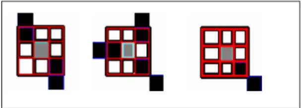
Fig.6: cn (p)=2,cn (p)=3 and cn (p)=1 representing a nonminutiae region, a bifurcation and a ridge ending
Crossing numbers 1 and 3 correspond to ridge endings and ridge bifurcations respectively. An intermediate ridge point has a crossing number of 2. The minutiae obtained from this algorithm must be filtered to preserve only the true minutiae. The different types of false minutiae introduced during minutiae extraction include spike, bridge, hole, break, Spur, Ladder, and Misclassified Border areas. (See figure 7)
Fig. 7: Types of false minutiae A B
C D E F
A. Spike, B. Bridge, C. Hole, D.Break, E. Spur F. Ladder
The number of minutiae in a given area is also limited therefore the minutiae density must also be kept in check. In order to filter out these false minutiae a 3 level-filtering process is applied:
Level 1: Removes the false ridge endings created as a result of the application of minutiae extraction algorithm at the ends of the thinned image.
Level 2: Removes the first five types of minutiae mentioned above using the rule based morphological minutiae filtering approach given by .
Level 3: This stage limits the maximum number of minutiae present in the thinned image to a pre-specified threshold.
A minutiae m is described by the triplet m={x, y, θ}, where x, y indicate the minutiae location coordinates and
θ denotes the minutiae orientation, which is the orientation evaluated for the minutiae location from the orientation image obtained during the enhancement process. The minutiae type is not being used during the matching process since minutiae type can be inverted due to enhancement and binarization steps [6].
Fig. 8: Filtered and Unfiltered Minutiae Sets
In this process we use text files as databases. We consider three text files for storing the bifurcation information , the ridge information , and the thermal parameters respectively. Every time a new fingerprint image is operated upon , a set of two text files are generated along with another file for keeping information about the person whose fingerprint is under checking. In case of verification , the text files generated are matched with the existing ones and the numbers of matches are displayed.
Let T and I be the representation of the template and input fingerprint, respectively. Let the minutiae sets of the two fingerprints be given by:
n
j
y
x
m
m
i
y
x
m
m
m
m
I
m
m
m
T
j j j j i i i i n n...
1
},
'
,
'
,
'
{
...
1
},
,
,
{
}
'
.,
,...
'
'
{
}
.,
,...
,
{
2 , 1 2 1
(3)A minutia mj’ in I and a minutia mi in T are
considered to be matched if their spatial and
orientation differences are within specified
thresholds ro and
θ
o. Minutia matching was
carried out by using the approach given in . In
this approach the minutiae sets are first
registered using a derivative of the Hough
transform followed by fingerprint matching
using spatial and orientation-based distance
computation. The matching algorithm returns a
percentage match score, which is then used to
take the match-no match decision based on the
security criterion[6].
4. Result and discussion
To study the performance of the proposed work, we consider the database containing 350 images. There are 10 different impressions per finger. Here we assume that images should be of good quality with at least 500 dpi and noise level, if any, of the image should be removed by the preprocessing. The performance of the system has shown the efficiency about 97% in 5.8 seconds .It has been seen that when the core point is correctly located, the translation invariant property of features is satisfied and the rotation handled in the matching stage is very fast. As result of which the matching process becomes very fast.
5. Conclusion
The paper presents different steps involved in the development of a fingerprint based person identification and verification system. And the proposed fingerprint recognition system uses both frequency and orientation information available in fingerprint. Due to this , the existing system become
more reliable . This system needs some extra cost and more processing time, but one can not compromise with the security.
References
[1] D.Maltoni, D.Maio, A.K.Jain, and Prabhakar, “Hand book of fingerprint Recognition “. Springer,2003
[2] V.Espinosa-Duro., “Minutiae detection algorithm for fingerprint recognition”, IEEE Aerospace Electron . Syst. Mag. 17(3),7-10,2002
[3] D. Manolescu, “Feature extaction – a pattern for information retrieval”, In Proceedings of the 5th Pattern Languages of Programming, Monticello, Illinois, USA, August 1998.
[4] A.K.Jain, “ Fundamentals of Digital Image Processing”, PHI, ISBN-13:978-013336150
[5] Dario Maio, Davide Maltoni, “Direct Graay-Scale Minutiae Detection In Fingerprints”, IEEE Transactions on Pattern Analysis and Machine Intelligence v.ol. 9 n.o.l, pp., 27-40, January 1997
[6] F.A.Afsar, M.Arif and M.Hussain, “Fingerprint Identification and Verification System using Minutiae Matching”, National conference on Emerging Technologies 2004
[7] Bhupesh Gour, T. K. Bandopadhyaya,Sudhir Sharma, “Fingerprint Feature Extraction Using Midpoint ridge Contour method and Neural Network”, IJCSNS International Journal of Computer Science and Network Security, VOL.8 No.7, July 2008