An approach for Minutia Extraction in Latent
Fingerprint Matching
Vaibhav Jain
M. Tech. Student in Computer Science and Engineering at Meerut Institute of Engineering and Technology, Meerut, U.P, India
Ajay Kumar Singh
Professor in Computer Science and Engineering at Meerut Institute of Engineering and Technology, Meerut, U.P, India
Abstract: Biometrics is the most widely used area which helps in identifying a person. It is true that each person has unique fingerprint. A fingerprint has different type of minutiae and it is one of the most popular categories used in fingerprint verification. The science of fingerprinting has been used for many years as a tool for identification. It is the process used to determine whether two sets of fingerprint detail come from the same finger. Automatic and reliable extraction of minutiae from fingerprint images is a critical step in fingerprint matching. The quality of input fingerprint images plays an important role in the performance of automatic identification and verification algorithms. This paper presents a robust alignment algorithm to align fingerprints and measures similarity between fingerprints by taking both minutiae extraction and oriented field information.
Index Terms: Fingerprints, Ridge, Furrow, local descriptors Hough transforms, ROI, h-break.
I. INTRODUCTION
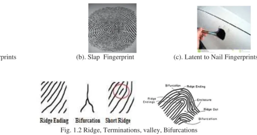
A fingerprint is the pattern of ridges and valleys on the finger tip. A fingerprint is thus defined by the uniqueness of the local ridge characteristics and their relationships. Minutiae points are these local ridge characteristics that occur either at a ridge ending or a ridge bifurcation. A ridge ending is defined as the point where the ridge ends abruptly and the ridge bifurcation is the point where the ridge splits into two or more branches. There are 3 types of fingerprints as shown in figure 1.1. It can be classified based on capture [1]: (a). Nail to Nail or Rolled: These fingerprints are taken from the rolling the finger on the device nail to nail or rolled fingerprints. (b). Slap or Plain: Simply put the finger on the plain paper. (c). Latent: These fingerprints are found at the time of crime. Many researchers research nail to nail and slap fingerprints over a year ago, but an important task is to recognize latent fingerprints. Fingerprint contains many ambiguous patterns of stripes called ridges and in ridges there exits some gap called valley. Ridges are the dark line of the image while the white area between the ridges is valleys. Ridges can be divided into 2 ways (a). Termination – When the ridges are at end point and (b). Bifurcation – When two ridges are divided into two as shown in figure 1.2. Minutiae consist of two basic type termination and bifurcation.
Fig. 1.1 (a). Nail Fingerprints (b). Slap Fingerprint (c). Latentto Nail Fingerprints
Fig. 1.2 Ridge, Terminations, valley, Bifurcations
II. DISTORTED ACQUISION OF LATENT BIOMETRIC DATA
By using marginal or boundary we can differentiates two different fingerprints. The following points may be beneficial for distinguish the two different types of fingerprints:
• Distortions: It can be categories into two parts. (a). Elastic distortions: These type of distortion are non-linear in nature as for example stretched skin shown in figure 2.1.
Fig. 2.1 Elastic Distortion
(b). Inelastic Distortion: It is a measure of distance for example rotation of object.
• Occlusions: Occlusion is that part of biometrics which is not clearly visible because of shadow, clothing etc. • Medical: Medical conditions are also responsible for distortions of image. For example if some chemicals are place on the finger then the fingerprints may not give good result.
• Antiquity: In a long run the fingerprint may vary and it may not match with the fingerprint store in a database. • Clothing: Because of clothing we may not have good result such as hats, glass and contract lens.
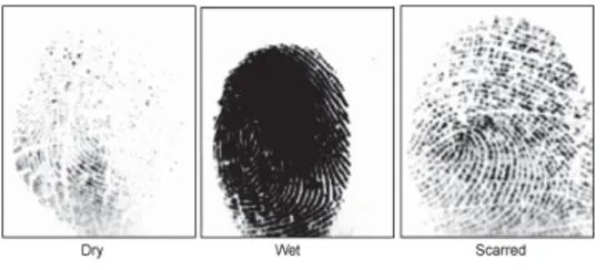
• Environment: It can also effect the biometrics traits and it may introduce additional noise in the original data shown in figure 2.2 [3].
Fig. 2.2 Effects of weather on fingerprints
• Ergonomics: The position plays important roles in biometric system. Placement of the finger on the object is not proper.
III. PREVIOUS WORK
The term biometrics has taken the very wide area in the field of security concerns. Fingerprints recognition is considered to be the most powerful technique for security and authentication. For identifying the fingerprints we need the better quality of images. Sometimes we find bad quality of image so enhancing the quality of an image we have many proposed algorithm and methods to eliminates the noise. Introduction of region mask generation and Gabor filter to get a high quality or enhanced fingerprints image [4]. Introduction of Directional Weighted Median Filter (DWMF) to remove the background noise [5]. Introduction of Short Time Fourier Transform (STFT). This technique estimates all the intrinsic properties of the fingerprints [6]. Introduction of an adaptive filtering and taken two result and compare them [7]. Introduction of an alignment algorithm like descriptor based Hough transform to align fingerprints [8, 1]. Introduction of extraction techniques that is used binarization, thinning and features extraction method [9]. Introduction of the M_join algorithm for join the broken curve due to the low pressure [10]. Introduction to the touchless fingerprints recognition system is described [11, 2].
IV. PROPOSED ALGORITHM
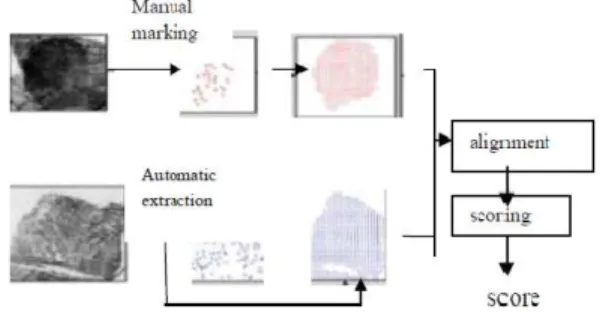
Suppose we have a latent fingerprint which we found at the place of crime and a rolled fingerprint, we manually marked these fingerprints and extract the additional features align them in the same coordinate system and compute match score between them as shown in figure 4.1 [12, 1].
Fig. 4.1 Manual marking for match score
This matching approach uses minutiae and orientation field from both latent and rolled prints. By the latent examiners we extract the minutiae. Orientation field is reconstructed from minutiae location and direction. It can be used in several ways to improve fingerprint matching performance and we can use several steps [13] shown in figure 4.2.
Fig. 4.2 Flow Chart of Algorithm
The direction of manually marked minutiae is very reliable, [14] the orientation field reconstructed using this approach is quite accurate except in areas absent of minutiae or very close to singular points as shown in figure 4.3.
Fig. 4.3 Orientation field reconstructed
Remove Spurious Histogram equalization
Fast Fourier Transform
Block Dir Estimation
ROI Area Load image
Hough Transform Remove h-breaks
Thinning
Removing Spikes
Save
V. STEPS FOR PERFORMING THE ABOVE FLOW CHART
(1). Load Image:We take two set of fingerprint images, the following below steps are determines weather the two sets of fingerprints are from the same finger or different.
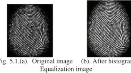
(2). Histogram Equalization:It is to expand the pixel value distribution of an image so as to increase the perceptional information [15]. The original histogram of a fingerprint image has the bimodal type, the histogram after the histogram equalization occupies all the range from 0 to 255 and the visualization effect is enhanced as shown in figure 5.1.
Fig. 5.1.(a). Original image (b). After histogram
Equalization image
(3). Fast Fourier Transform (FFT):In this method we divide the image into small blocks 32x32 [16].
For u = 0, 1, 2 … 31 and v = 0, 1, 2... 31
(4). Block Direction Estimation:Two basic steps are involved in block direction estimation.
1. We calculate the gradient along x and y direction for each pixel. For this purpose sobel filter can be used.
2. For each block we calculate least square approximation. The tangent value of a block direction is calculated.
The block direction is shown in figure 5.2 [17].
Fig. 5.2 Direction Map
(5). ROI Area:A criminal can hold an object and from there we have to extract his fingerprints. Hence instead of taking the entire hand image we have to concentrate to his fingerprint so the region of interest will be only the fingerprint not the entire palm. In this we use two morphological operation named as open and close. Open operation increase the image and we remove peak that is caused by background noise. Close operation reduces the image and remove small cavities as shown in figure 5.3 [18].
Fig. 5.3 (a). Image (b). After Close operation
(6). Thinning Process: The binary image obtained is now converted into the one pixel wide skeleton which is known as thinning. The process of thinning includes two processes: (a) Ridge thinning: It eliminates redundant pixels of ridges till the ridges are 1 pixel wide. In each scan of the full fingerprint image, the algorithm marks down the redundant pixels in each small image window of (3*3) matrix and finally removes all those marked pixels after several scans. (b) Skeleton Refinement: This operation takes thinned image as the input and produces refined skeleton image by converting small straight lines to curve to the maximum possible extent as shown in figure 5.4 [19].
Fig. 5.4 Thinning
(7). Remove h-breaks:H points are those points which act as noise and must be eliminated [19]. These are wrong minutiae which can further be shaped by removing h-points as shown in figure 5.5.
Fig. 5.5 Remove h-breaks
(8). Removing Spikes:It is unwanted dots or spots found in an image so removal of spikes is important for matching the fingerprint from the given database as shown in figure 5.6.
Fig. 5.6 Removing spikes
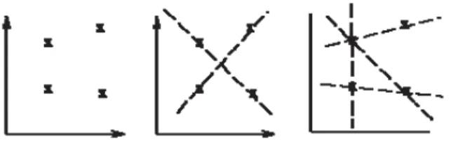
Fig. 5.7 Classical Hough transformation
The generalized Hough transform is used when the shape of the feature that we wish to isolate does not have a simple analytic equation describing its boundary. In this case, instead of using a parametric equation of the curve, we can use a look-up table to define the relationship between the boundary positions and orientations and the Hough parameters. For example, suppose that we know the shape and orientation of the desired feature as shown in figure 5.8. We can specify an arbitrary reference point (Xref, Yref) within the feature, with respect to
which the shape i.e. the distance r and angle of normal lines drawn from the boundary to this reference point (
Z
) of the feature is defined. Look-up table (i.e.R-table) will consist of these distance and direction pairs, indexed by the orientationZ
of the boundary.Fig. 5.8. Description of R-table components.
The Hough transform space is now defined in terms of the possible positions of the shape in the image, i.e. the possible ranges of (Xref, Yref). In other words, the transformation is defined by:
) sin( ref
) cos( ref
E
E
r Y Y
r X X
r and ȕ values are derived from the R-table for particular known orientations (
Z
). If the orientation of the desired feature is unknown, this procedure is complicated by the fact that we must extend the accumulator by incorporating an extra parameter to account for changes in orientation.Algorithm: Suppose the object has undergone some rotation ࠴ and uniform scaling s:
(p’, q’) --> (p’’, q’’) p" = (p’cos(࠴) – q’sin(࠴))s p" = (p’sin(࠴) + q’cos(࠴))s Replacing p’ by p" and q’ by q":
pc = p – p" or pc = p - (p’cos(࠴) – q’sin(࠴))s
pc = q – q" or qc = q - (p’sin(࠴) + q’cos(࠴))s
Step 1. Initialize the Accumulator table: Ac[pcmin. . . pcmax][qcmin. . . qcmax][qmin . . .qmax][smin . . . smax]
Step 2. For each edge point (p, q)
p' = rcos(Į) q’ = rsin(Į)
for(࠴ = ࠴min; ࠴ ࠴max; ࠴++)
for(s = smin; s smax; s++)
pc = p - (p’cos(࠴) – q’sin(࠴))s
qc = q - (p’sin(࠴) + q’cos(࠴))s
++(Ac[pc][qc][࠴][s])
Step 3. Possible locations of the object contour are given by local maxima in Ac[pc][qc][࠴][s]
If Ac[pc][qc][࠴][s] > T, then the object contour is located at (pc, qc), has undergone a rotation ࠴, and has been
scaled by s.
(10). Remove Spurious: Some of the points in the fingerprints are seems to be original but there are not original. So we must removal these type of supurious data as shown in figure 5.9.
Fig. 5.9. Removal defected lines
(11). Save: After following above these steps we save the result in our database. When all the matches are completed then we found the best percentage result in our database.
(12). Match: In this stage we make a rectangle box and try to match with the database. This box keeps on moving throughout the ROI for matching the entire fingerprint till our goal is achieved. Finally the ratio of two fingerprints is calculated by the ratio of total match pair over the number of minutiae [19].
VI. CONCLUSION
In this paper we mostly describe the hough transformation. A generalized hough transformation is superior then the hough transformation because it can gives the result in any shape or direction. We remove the h points, spikes and spurious sign and takes only those minutiae points which are in under region of interest.
ACKNOWLEDGMENT
We are grateful to Chairman, Director, HoD for there full support.
REFERENCES
[1] A. A. Paulino, J. Feng, and A. K. Jain, “Latent fingerprint matching using descriptor based Hough transform”, International Joint Conf. on Biometrics, pp. 1–7, October 2011.
[2] Amrata A. Khindre1 and V. A. More, “An Approach to Touchless Fingerprint Recognition Using Matlab”, International Journal of Emerging Trends & Technology in Computer Science (IJETTCS) - Volume 3, pp. 4, July-August 2014.
[3] Ruggero Donida Labati, Angelo Genovese, Vincenzo Piuri and Fabio Scotti, “Touchless Fingerprint Biometrics: A Survey on 2D and 3D Technologies”, Journal of Internet Technology Volume 15, No.3, 2014.
[4] Lin Hong, Yifei Wan, Anil Jain, “Fingerprint Image Enhancement: Algorithm and Performance Evaluationۅ” IEEE Transactions On Pattern Analysis And Machine Intelligence, Volume. 20, pp. 8, August 1998
[5] Yiqiu Dong and Shufang Xu., “A New Directional Weighted Median Filter for Removal of Random”, Valued Impulse Noise. Volume 5(9), pp. 2-4, April 2001.
[6] Sharat Chikkerur, Alexander N. Cartwright and Venu Govindaraju, “Fingerprint enhancement using STFT analysis”, Elsevier, pp. 198-211, 25th May 2006.
[7] And-elija M. Raißcevi´c and Brankica M. Popovi´c, “An Effective and Robust Fingerprint Enhancement by Adaptive Filtering in Frequency Domain”, Facta Universitatis (NIßS), Ser.: Elec. Energ. Volume. 22, no. 1, pp. 91-104, April 2009.
[8] Saurabh Yadav and Ajay Kumar Singh, “A Biometric Traits Based Authentication System for Indian Voting System,” International Journal of Computer Application (IJCA), ISSN: 0975-8887, Volume 65, no.15, pp. 159-162, March 2013.
[9] Romulo Ferrer L. Carneiro and Jessyca Almeida Bessa, “Techniques of Binarization, Thinning and Feature Extraction Applied to a Fingerprint System”, International Journal of Computer Applications (0975 8887) Volume 103 - No. 10, pp. 4, October 2014. [10] Rajendra Kumar and Saurabh Sharma, “Paradigm Shift in Fingerprint Recognition on Pressure Variation and Impact of Information
System in Crime Reduction”, Global Journal of Enterprise Information System, Volume 1, Issue 1, pp. 88-93, Jan 2005.
[12] Anjali Sharma and Ajay Kumar Singh, “CBIR through CDH using Query by Group,” International Journal of Computer Trends and Technology (IJCTT), ISSN: 2231-2803, Volume 28, no. 1, pp. 21-27, October 2015.
[13] Sony Polumata and L.Padmalatha,“ Latent Fingerprint Matching based on Texture Descriptor using Hough Transform”, International Journal of Computer Applications (0975 – 8887) Volume 106 – No.17, November 2014.
[14] F. Chen, J. Zhou and C. Yang, “Reconstructing Orientation Field from Fingerprint Minutiae to Improve Minutiae Matching Accuracy”, IEEE Transactions on Image Processing, Volume 18, no. 7, pp. 1665-1670, July 2007.
[15] L. Ravi Kumar, S. Sai Kumar, J. Rajendra Prasad, B. V. Subba Rao and P. Ravi Prakash, “Fingerprint Minutia Match Using Bifurcation Technique”, S Sai Kumar et al, International Journal of Computer Science & Communication Networks,Volume 2(4), pp. 478-486, March 2011.
[16] Amandeep Kaur and Ameeta, Babita, “Minutiae Extraction and Variation of Fast Fourier Transform on Fingerprint Recognition”, International Journal of Engineering Research and General Science Volume 2, Issue 6, October-November, 2014.
[17] Manu Garg and Er. Harish Bansal, “Fingerprint Recognition System using Minutiae Estimation”, IJAIEM, Volume 2, Issue ISSN 2319 – 4847, 5 May 2013
[18] P. Gnanasivam and S. Muttan, “An efficient algorithm for fingerprint preprocessing and feature extraction”, ICEBT , Procedia computer Science, Volume. 2, pp.133-142, oct 2010.