for close aerial surveillance
Alexandru-Marius PANAIT*
*Corresponding author
INCAS – National Institute for Aerospace Research “Elie Carafoli”
B-dul Iuliu Maniu 220, Bucharest 061126, Romania
mariusp@incas.ro
Abstract: Close air support of ground troops especially in densely populated, urban environments has an ever increasing prevalence in the modern warfare. Counter-terrorism activities as well as land-based “surgical strikes” impose a set of special requirements on all the used weapons and equipment so as to minimize weight, cost and complexity and maximize efficiency. Small scale UAVs are in service with all the armed forces around the globe; micro UAVs are emerging as the ground troop close support preferred solution. Endurance and range of these devices is regularly small to very small, and their speed is low. Their small size makes them virtually un-targetable if somewhat still detectable. A new generation of micro-drones is proposed, with a higher speed (up to 350 km/h ground speed averaged) and automatic recovery system. Project SKYLARK consists of a reusable minimal micro-UAV featuring a portable micro-USB camera and an aerodynamically assisted timer-based recovery system.
Keywords: micro-UAV, aerial surveillance, low-cost aerial surveillance platform
1. INTRODUCTION
The “Skylark” project consists of a small crossbow-launched, recoverable projectile that features a USB micro-camera with on-board accumulators and a tail section that has a piezoelectric-actuated wing control that after a certain time after launch curves the tip of a wing so as to put the drone on a descending spiral.
During the controlled descent the camera that is mounted sidewise films the panoramic view in rotation.
The proper landing phase consists in a controlled impact on the rubber padded underside of the fuselage.
There is no engine present in the Skylark, the necessary kinetic energy coming from the crossbow launcher.
The proposed method is sufficient to launch a small (under 400 g) UAV with an initial speed of up to 350 km/h on an angled trajectory and giving it sufficient power to reach altitudes of up to 60 meters or higher.
From that vantage point, given the short focal length of the camera pinhole lens, an area of approximately 12 square kilometers can be imaged. Improved versions of the “Skylark” will be able to climb to higher altitudes by use small motors and propellers, but for the moment the pilot project, the concept demonstrator, only aims to perfect the recovery and controlled descent part of the problem.
The body of the micro-UAV can be made out of thin PVC tubing or constructed of carbon fiber and epoxy resin if necessary.
The wings and fixed tail unit are also of a very light construction, and thin acrylic sheet -perhaps transparent - could provide for a lower observability of the craft.
The nose unit consists in a carbon fiber and epoxy tube filled with ballistic gelatin or a similar impact-absorbing material that will distribute forces evenly on the small USB camera it protects.
The camera unit fits inside the nose unit by friction. Its pinhole lens does not need a large aperture in the tube that also helps with installation and alignment.
For this specific micro-UAV a special profile and planform were chosen for the wing; the rudder unit has an inverted profile to help stabilize the craft by creating “negative lift”. [2] The profile contour is chosen in accordance with the necessities of a small, unpowered micro-UAV that has to fly a short distance but with a good altitude gain at a moderate to high speed of up to 350 km/h (leading to an even higher scaled speed considering its general dimensions).
Because of the lack of any propelling devices, apart from the initial impulse received from the launcher, it has to minimize air friction and thus efficient, elliptical wings having a low vortex drag were chosen for this [1,2].
Also the wing has a slanted tip, so as to obtain some end-plate effect to minimize circulation along the chord from the inner to the outer wing.
2. THE “SKYLARK” PROJECT
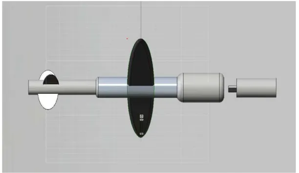
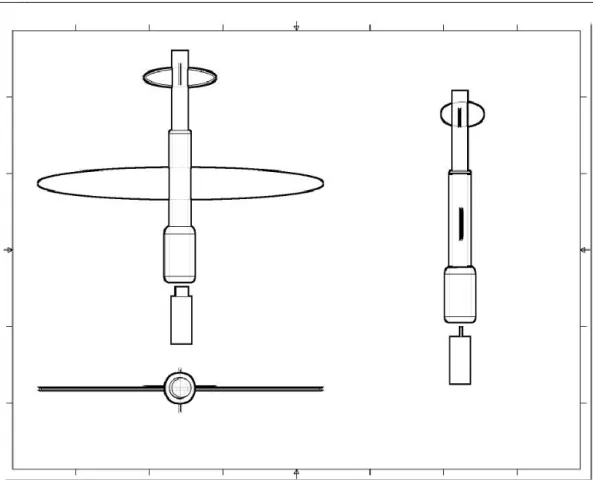
The first Skylark configuration is shown below, along with the load - the USB micro camera that will be fitted in the forward fuselage container (figure 1):
Fig. 1 The initial Skylark configuration, technology demonstrator phase
Fig. 2 The “Skylark” layout - general view of the aircraft and its micro camera
The choice of a launching apparatus was made on grounds of simplicity and portability, as by using a crossbow-style launcher it is not necessary to carry compressed gas cartridges or bulky hydraulic ramps, and the trajectory can be controlled very well using a small ballistic computer attached to the crossbow (Figure 3).
The ballistic computer is a small microcontroller-based simple calculator for trajectories that accepts input in terms of drone weight, configuration and launch angle and predicts speed, height and distance to recovery area.
By using a slide-contact type of socket the internal timer for the recovery mechanism of the Skylark drone can be reset prior to launch so as to ensure the necessary coverage and height prior to aerodynamically unbalancing the small aircraft so as to drive it in a controlled spin-crash trajectory (recovery phase).
Figure 3 shows a proposed configuration for the launching device. Such a launcher could, for a given draw weight of approximately 70 to 80 kg, propel a low-drag projectile of up to 400 grams with initial speeds of up to 350 km/h [3].
At these draw weights an external cocking device is required, such as a crannequin or goat’s foot lever.
Fig. 3 The proposed launching apparatus-inspired by [3]
The ballistic computer has two main functions: the first is to accept input from the user in the form of probe/drone configuration, weight and desired coverage, calculating the necessary launch angle (with an optional function to indicate when it was achieved) and the second is to estimate the speed and height, and thus the imaged area.
It also resets the timer that delays the impulse to the piezoelectric actuator that unbalances the probe after the maximal height is reached so as to inscribe it on the descent trajectory. There is no transmission equipment on the “Skylark” prototype, useful data being recovered with the drone taken apart (it consists of only two independent parts, the USB mini camera and the supporting fuselage-wing-tail-unit block.
Micro cameras like these can weigh no more than 30 grams and carry a micro-SD card of up to 16GB, more than enough for the short missions of the ground-launched “Skylark” (no more than 10 minutes flight time).
There is a possibility for such small size drones to be dropped out of flying carriers or even rocket-launched (small size mini-rockets) that will enable them to glide more and reach higher altitudes, and thus covering more space but in this case, recovery can be difficult and they should be equipped with a tracking/homing device.
The flight of the small “Skylark” probe is unpowered, and for level flight the lift L should equal total weight W. Still, the expected trajectory from a well - balanced probe is a parabola; hence we can write the equations for lift and drag as (1) and (2), for a portion of inclined trajectory of unpowered gliding:
)
cos(
*
W
L
(1))
sin(
*
W
D
(2)where L = lift, D = drag and alpha = incidence or glide angle.
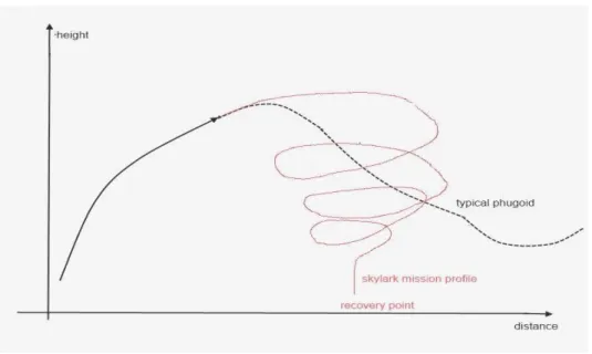
3. MISSION PROFILE FOR THE “SKYLARK” PROBE
for the Skylark probe as opposed to free gliding. The needed destabilization is acquired by using a special oscillator that feeds a piezoelectric actuator. This actuator is connected to an asymmetric control surface that induces a high asymmetry in the wing by opening an airbrake-like device on one half-wing only, thus by virtue of higher induced drag causes rotation towards that wing tip.
Fig. 4 Skylark typical mission profile
To maximize the reached altitude, a low vortex drag planform of an elliptical shape with a rather high wing loading were chosen.
Gliding performance is not so much of an issue here as the speed of the craft is initially high and then drops as it reaches the maximum altitude, but the incoming stall is not a problem as it is meant to limit the travel of the probe and start the recovery phase.
In case of pointed wing tips, classical aerodynamic theory predicts high local lift coefficients and low Reynolds numbers leading to tip stall and flow separation.
This increases profile and induced drag and must be avoided. Modern aircraft usually have wings with reasonable taper to prevent tip stall.
The elliptical wing has special profile adapted to low Reynolds flight; a modified NACA 0002 ultra-thin with a slight camber at 60 to 80 % of the chord is to be utilized for best performance in this application [1, 2, and 4].
The intended recovery mechanism implies aerodynamically destabilizing the aircraft, by forcing it into a flat spin.
The lift is drastically reduced while it comes spiraling to the ground. The first two or three turns are in fact the objective of its mission: collecting panoramic views from above the target area, imaging a large area while it spins.
Later turns at ever increasing speed and decreasing altitude are not useful but images can be edited out later.
The presented method allows for an inexpensive device to capture and deliver panoramic images of the surrounding environment without the need of an expensive guiding system.
4. ESTIMATED FIGURES FOR THE “SKYLARK” PROBE
Total length: 150 mm
Wing span: 120 mm, aspect ratio: 4.2, wing loading: 0.6633 g/cm3
Wing root chord: 40 mm, lifting surface: 0.015076 m2, mean aerodynamic chord: 38.5699 mm Wing profile: modified NACA 0002
Net weight: 100g (including batteries and camera) Total weight (including a 16GB micro SD card):110 g. Power supply: in-camera micro accumulators
Power plant/propulsion: none (glider)
Auxiliary electronic system (for forced flat spin inducer): two LR13 batteries
Materials: camera housing: PVC tube, epoxy resin; urethane foam; wings: depron or thin PCV sheet; fuselage: carbon fiber and epoxy resin;
5. CONCLUSIONS
A small-scale experimental program could verify the project’s claims and could lead to the development of a new product within our institute.
The Skylark probe is an extremely low cost, rugged imaging platform suitable for small scale deployment and also an excellent micro UAV flying test bed for guidance systems, micro-instrumentation, low altitude aerial probing and micro UAV propulsion devices.
REFERENCES
[1] R. H. Barnard, D. R. Philpott, Aircraft Flight: A Description of the Physical Principles, ISBN: 0273730983, 9780273730989, Editor: Pearson Education, 2010.
[2] Martin Simons, Model aircraft aerodynamics, Publisher: Hemel Hempstead, Hertfordshire: Argus Books, 1994, 3rd ed., ISBN: 1854861212 9781854861214.
[3] Sir Ralph Payne-Gallwey, The Book of the Crossbow, 1903, Longmans, Green &Co, London (reprinted Dover ed. 7, 2009), ISBN 10: 0486287203, ISBN 13: 9780486287201.
[4] Peter J. Kunz and Ilan M. Kroo, Analysis, Design, and Testing of Airfoils for Use at Ultra-Low Reynolds
![Fig. 3 The proposed launching apparatus-inspired by [3]](https://thumb-eu.123doks.com/thumbv2/123dok_br/17255893.246014/4.744.237.548.134.339/fig-proposed-launching-apparatus-inspired.webp)