New active machine tool drive mounting on the frame
J. Švéda
a,*
, M. Valášek
a, Z. Šika
aa Department of Mechanics, Biomechanics and Mechatronics, Faculty of Mechanical Engineering, Czech Technical University in Prague,
Czech Republic
Received 10 September 2007; received in revised form 26September 2007
Abstract
The paper deals with the new active mounting of the machine tool drives. The commonly used machine tools are at this time mainly equipped with fix-mounting of the feed drives. This structure causes full transmission of the force shocks to the machine bed and thereby restricts the dynamic properties of the motion axis and the whole machine. The spring-mounting of the feed drives is one of the possibilities how to partially suppress the vibrations. The force that reacts to the machine tool bed is transformed thereby the vibrations are lightly reduced. Unfortunately the transformation is not fully controlled. The new active mounting of the machine tool drives allows to fully control the force behaviour that react to the machine body. Thereby the number of excited frequencies on the machine tool bed is significantly reduced. The active variant of the feed drive mounting is characterized by the synergistic cooperation between two series-connected actuators (“motor on motor”). The paper briefly describes design, control techniques and optimization of the feed drives with the new active mounting conception.
© 2007 University of West Bohemia. All rights reserved.
Keywords: machine tool, vibrations, active variant, control techniques
1. Introduction
The contemporary machine tools are characterized by using the fast in frame mounted feed drives. The linear axis is connected with the machine structure by the linear motor or rotary motor with the ball screw. The motor is fast inbuilt to the machine bed and presents a source of the motion force which reacts equally to the machine frame and motion axis. High value and wide frequency spectrum of the motion force is typical for the high dynamic machine tools. They have to quickly react to the position and velocity setpoint given by the control system. Various power shocks are transmitted to the machine bed during the operation and excite wide spectrum of the frequencies. Excited natural-frequencies are dangerous especially because of the vibrations amplification. Oscillation of the machine bed and motion axis is problematic for the precise machining and deteriorate dynamic properties of the motion axis and whole machine tool.
The paper deals with the advanced technique which transforms the frequency spectrum and amplitude of the reaction force. It allows to suppress the machine tool vibrations and thereby to improve dynamic properties of the motion axis. The technique is based on the feed drive motor mounted by the help of another motor which works as the vibroisolation – so called “motor on motor”.
The text is also briefly interested in the spring-mounting of the feed drives. It is mentioned as an intermediate stage between the common fix and the new active feed drive mounting.
2. Mounting principle of the feed drives
The principle of current solution of mounting feed drives and its new active variant with double motor is introduced in this chapter.
2.1. Fix-mounting
The fix mounting of the feed drives is a common case in the machine tool branch. It was partially described in the introduction of the paper - chapter 1. As shown in fig. 1, the same force reacts to the machine tool bed and motion axis. This simple solution is based on exploitation of the linear motor. It consists of the primary and secondary part. The primary part is made from steel plates and winding and it is fast connected to the motion axis, in this case to the spindle of machine tool. The secondary part consists of permanent magnets and it is fix-mounted to the machine bed tool.
Fig. 1. Contemporary machine tool feed drive mounting.
2.2. Spring-mounting
The spring-mounting [1] is more sophisticated method of linear feed drive construction. The configuration is shown in fig. 2 and it consists of the same parts as the fix mounting conception. The primary part of the linear motor is also fast connected to the motion axis that carries the spindle. The difference is in the mounting of the secondary part. There is used a spring that serves to the axial fixation to the bed.
This configuration allows movement of the secondary part of the motor in range cca ± 10 mm. The additional damping of spring connection is very important for the motion axis stability hence the viscose damper is applied. The efficiently of the whole method depends on the damper setting. The low damping value causes high motion amplitudes and long oscillation tail, the high damping value deteriorates efficiency of the method - increases shocks that are transmitted to the machine bed.
Fig. 2. Spring-mounting of the machine tool feed drive.
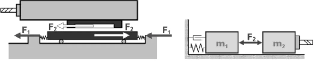
2.3. Active-mounting – “motor on motor”
The “motor on motor” conception is a new concept of feed drive construction. As shown in fig. 3, this variant consists of two independent linear motors. One of them (F2), represents common feed drive which causes displacement of motion axis. The second one deals with the reaction force transformation (F1). We can say, that the second one works as the vibroisolator and the movement is splitted into two parts [2].
The main advantage of the solution is possibility to fully control force which reacts to the machine tool body. In this way we can transform the reaction force in an effort to suppress vibrations of the body structure.
The paper deals mainly with this new concept of the feed drive mounting.
Fig. 3. “Motor on motor” conception.
3. Impulse decoupling technique
High performance machining is characterized by high dynamic positioning of the motion axis, typically by high value of Kv (position regulator gain). In such operation the actuator force shape is extremely sharp, ideally it looks like force step. Unfortunately this impulse frequency spectrum is very wide and many frequencies are excited. It is closely connected with excitation of the vibrations.
In the new feed drive concept the motor (F2) can be controlled by the common cascade controller. The main idea of the control is to react by the additional force (F1) before the
control system demands change of the main force (F2). The NC code corresponding to the
actuator (F2) has to be known because of the efficient control of the actuator (F1). By this we can prepare better initial condition for the motion of the main axis and profit from the movement of the additional motor mass (m1).
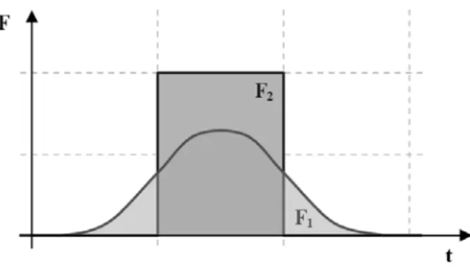
The time behaviour of the forces can look like in fig. 4. As shown in fig. 4, force which acts to the bed (F1) has smoother time behaviour and starts earlier than the force (F2) which reacts to the spindle. This impulse decoupling system decreases the force amplitudes which reacts to the bed and reduces the number of excited frequencies.
4. Optimization
The suitable shape of the force (F1) depends on the various conditions. Therefore it is necessary to use some mathematical method for its obtaining [3], [4]. Two methods of the optimization are used.
The first one exploits the genetic algorithm for the searching minimum of the target function (1)
( )
∑
(
)
∑
− = + → = − ⋅ + ⋅ + ⋅ = 1 1 2 1 3 2 1 0 2 1 2 1 max n i i i t n ii c x c F F
F c
tf . (1)
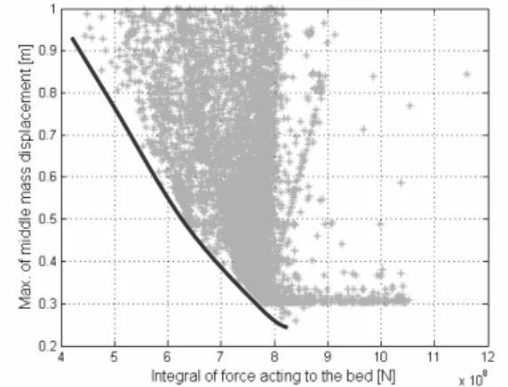
The output of the solution has many resulting points which are shown in fig. 5. Each point in the figure represents one solution of the target function and from our point of view the solutions that are located on the red line are interesting. This line represents the pareto-set, where both shown criterions are minimal. It means, by reducing value of the one criterion, the second one is increasing.
Fig. 5. Genetic algorithm optimization results. Fig. 6. Quadratic programming optimization results.
One point of the pareto-set is chosen as the final result of the optimization. The optimized force time behaviour is corresponding to that point. The method is extremely time consuming and many results are redundant (only points located on pareto-set are interesting).
Another method for the force impulse optimization exploits the quadratic programming algorithms. The method is based on the analytic computation of the target function minimum (2)
(
)
∑
∑
∑
= − = + = ⋅ + ⎟ ⎠ ⎞ ⎜ ⎝ ⎛ − + + ⋅ + ⋅ = n i i n n i i i n ii c F F F F c x
F c tf 1 2 1 3 2 2 1 1 1 2 1 2 1 2
1 . (2)
The time behaviour of the optimized force is shown in the fig. 7. The shown characteristics are relevant to the selected equivalent points on the pareto-sets of the each optimization method.
0 0.1 0.2 0.3 0.4 0.5 0.6 0.7 0.8 0.9 1
-1000 0 1000 2000 3000 4000 5000 6000 7000 time [s] fo rc e [ N ] motion force
reaction force - genetic algorithm reaction force - quadratic programming
0 0.1 0.2 0.3 0.4 0.5 0.6 0.7 0.8 0.9 1
-1000 0 1000 2000 3000 4000 5000 6000 7000 8000 9000 time [s] fo rc e [N ] fix-mounting motor on motor spring mounting
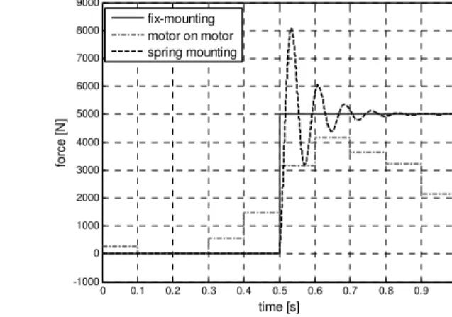
Fig. 7. Time behaviour of the optimized force. Fig. 8. Comparison of the impulse decoupling methods.
As shown in the fig. 7, the time behaviour of the reaction force is similar in both optimization principles. The final shape of the reaction force is also equivalent to the designed shape in fig. 4. It starts to react earlier then the main motion force (F2) and has a reduced amplitude.
The comparison of the reaction force between the fix, spring and active mounting is shown in the fig. 8. The spring-mounting principle transforms the reaction force shape but the force amplitude has very high value and is connected with the vehement oscillation.
It is extremely difficult and time consuming to fully optimise the reaction force shape. This is the main reason why the time behaviour is splitted into the discrete time steps in which the optimization force is constant. Unfortunately such force shape is problematic, it looks like the steps and the frequency spectrum of the signal is not suitable. As shown in the fig. 9 the profile of the optimized force has to be interpolated by a cubic spline in the each time interval. Such time behaviour is useful and can by used in the simulations.
0 0.1 0.2 0.3 0.4 0.5 0.6 0.7 0.8 0.9 1
-500 0 500 1000 1500 2000 2500 3000 3500 4000 4500 time [s] fo rc e [N ] accuracy points interpolated force force after optimization
0 0.05 0.1 0.15 0.2 0.25 0.3 0.35 0.4 0.45 0.5
-10 0 10 20 30 40 50 60 70 80 90 Frequency (kHz) P o w er /f requ ency ( dB /H z )
Power Spectral Density Estimate
fix-mounting spring mounting motor on motor
Fig. 9. Time behaviour of the optimized force. Fig. 10. Power spectral density comparison.
design. The time behaviour of the reaction force is not so sharp and lower number of the frequencies is excited. Finally the best solution is based on the “motor on motor” construction. As shown in fig. 10, the power spectral density of the decoupled reaction force impulse is the best of all. Number of excited frequencies is minimal and their amplitudes are lower then by the spring or fix-mounting conception.
5. Conclusion
The designed technology for the impulse decoupling brings new level of the motion dynamic to the machine tool branch. We can achieve reduction of the reaction forces and excited frequencies by exploitation the new decoupling principle. The machine tool equipped with the “motor on motor” conception will be protected from the vibrations and allows high dynamic and precise machining.
The technology is based on the possibility to fully control the reaction force. It is possible thanks to the additional active actuator that is in series connected to the main motion motor.
The main target of the paper is to introduce the method and its exploitation in machine tool branch. The mentioned optimisation and simulation is focused only for the specific machine tool operation and the development of the universal control scheme equipped with the “motor on motor” principle is researched at this time.
Acknowledgement
The authors appreciate the kind support by MSMT project MSM 6860770003 “Development of algorithms of computational simulations and their applications in engineering”.
References
[1] A. Bubák, Zvyšování dynamiky a přesnosti posuvových os obráběcích strojů, Ph.D. thesis, ČVUT, Praha, 2004.
[2] M. Karabbes, R. Neugebauer, S. Ihlenfeldt, T. Schröder, Reactive Splitting into Dynamic Components for Overlayed Drive Structures, The 4th Chemnitz Parallel Kinematics Seminar, Chemnitz, 2004, pp. 247– 256.