Vol. 10, June 2012 340
Perspective Application of Passive Optical Network with Optimized
Bus Topology
P. Lafata*, J. Vodrazka
Department of Telecommunication Engineering Faculty of Electrical Engineering
Czech Technical University in Prague Prague, Czech Republic
ABSTRACT
Passive optical networks (PONs) represent a promising solution for modern access telecommunication networks. These networks are able to meet the increasing demands on transmission rate for demanding multimedia services, while they can offer typical shared transmission speed of 1.25 or 2.5 Gbps. The major role in deploying optical distribution networks ODNs plays the maximum attenuable loss, which is caused mainly by passive optical splitters. This paper proposes an innovative application of passive optical networks with optimized bus topology especially for local backbone data networks. Due to using only passive components, it is necessary to optimize certain parameters, especially an overall attenuation balance. Considering the possibility of such optimization, the passive optical network with optimized bus topology provides several interesting opportunities for specific applications. This paper will present selected aspects of passive optical networks and splitters with asymmetric splitting ratio. The essential part is focused on the practical demonstration of their use to optimize the passive optical network with bus topology, which acts as a local backbone network for structured cabling systems, and for local data networks in large buildings.
Keywords: Bus topology, optimization, passive optical network, splitter.
1. Introduction
The present access telecommunication networks still mostly use metallic cables for xDSL digital subscriber lines or wireless networks, such as Wi-Fi or WiMAX. However, the transmission speed of current xDSL technology is limited by the disturbance and interference, i.e., crosstalk, which occurs during simultaneous operation of multiple xDSL lines in the same metallic cable, as described in [1] and [2]. While many wireless networks suffer similar problems of interferences among channels, especially when the given license-free frequency band is becoming depleted. The transmission speeds of xDSL and wireless technologies are low for modern demanding multimedia services, especially the IPTV broadcasting and generally video services distributed in high definition (HD). The passive optical networks (PONs) represent a new promising solution for the next generation of access networks.
Perspective Application of Passive Optical Network with Optimized Bus Topology, P. Lafata / 340‐346
Journal of Applied Research and Technology 341
The horizontal and vertical structured metallic cabling systems usually consisting of metallic UTP or STP (Un/Shielded Twisted Pair) cables are frequently used in large buildings, schools, hospitals, and industrial complexes. Their main purpose is interconnecting the local data switches, routers or hubs together to form a local backbone data network. However, the maximum distance between two active network elements is limited to 100 m and the maximum transmission speed between them is 1 Gbps. On the other hand, current PONs come into two basic types and they offer 1.25 or 2.5 Gbps transmission speed: GPON (Gigabit PON), as according to ITU-T G.984 [5] and EPON (Ethernet PON), specified by IEEE 802.3ah standard [6]. The following evolutionary step is the use of 10GEPON (10 Gigabit EPON) according to IEEE 802.3av standard [7] or ITU-T G.987 new type XG-PON [8], which can both reach shared transmission speed of 10 Gbps in downstream direction. That is why these PONs could form local high-speed data backbone networks for connecting local data switches and routers with transmission speed of 10 Gbps or more and they could effectively replace structured metallic infrastructures.
However, for such application, it would be necessary to use PON with a bus topology with many short branches for individual connection of each local data switch or router. The fundamental problem of the reported case is the high value of insertion loss and total attenuation of passive optical splitters. Due to the high attenuation, the bus topology of passive optical network is inefficient, because it is necessary to meet requirements to comply with an interval of minimum and maximum attenuation of all branches for the correct operation of the network. In this way, the number of terminal units (ONU/ONT, Optical Network Unit, and Optical Network Termination) is limited. One of the possible solutions may be the use of passive optical splitters with asymmetric division of the input power in the outgoing directions. The splitters can be constructed with either fixed optical power splitting ratio, or as tuneable optical splitters with controllable splitting ratio. Several technologies have been proposed to produce asymmetric optical splitters of both types with various types of their internal structure. Different methods of
achieving non-uniform splitting ratio have been utilized [9], [10].
This paper will present selected aspects of passive optical networks and splitters with asymmetric splitting ratio. The essential part is focused on the practical demonstration of their use to optimize the passive optical network with bus topology, which acts as a local backbone network for structured cabling systems, and for local data networks in large buildings.
2. Derivation of Elementary Equations for Asymmetric Splitter
The splitting ratio is a key parameter of the optical splitter. Generally, it indicates the total number of outgoing branches N of the splitter and is usually expressed as a ratio of 1:N. The splitting process itself is implemented by all-passive method, using elementary Y-junctions (a single Y-junction has a splitting ratio of 1:2), which can be made using short fibers fused together or using a planar technology. Subsequently, it is possible to obtain higher desired values of splitting ratio by cascading several elementary Y-junctions; therefore, the resultant splitters reach the number of outputs, being the square root of 2. An important parameter of the passive optical splitter is the value of its total insertion loss AC, which consists of the loss AD due
to the process of dividing the input optical power into N outputs and it also consists of the second part represented by a residual loss AZ [3]. The loss
AD depends on the splitting ratio 1:N (it depends on
the number of outputs N), the residual loss AZ
represents the additional loss of fibers, connectors, welded joint and its irregularity, manufacturing tolerations, etc.
It is possible to express some basic parameters of the elementary Y-junction.
The loss AD due to the dividing of input
optical power for the i-th branch:
10 log ; ,
i
in Di
out P
A dB W W
P
(1)
The summary output optical power:
;
i
out out i
Perspective Application of Passive Optical Network with Optimized Bus Topology,P. Lafata / 340‐346
Vol. 10, June 2012 342
The residual loss AZ is usually constant for
all i branches:
1 2 ; ; ;
Z Z Z Zi
A A A A dB dB dB dB (3)
The summary attenuation of the i-th branch:
;
,
Ci Di Zi
A
A
A
dB dB dB
(4)In the case of a symmetrical splitter with only one Y-junction (1:2 splitter) and a uniform splitting ratio of the input optical power to its outputs Pout1=Pout2=
0.5 Pin and splitting loss AD1=AD2= 3.01 dB.
2.1 Asymmetric splitter
The passive optical splitter with a non-uniform variable splitting ratio on its particular outputs can be made either with the fixed splitting ratio, or as a tunable optical splitter with the controllable splitting ratio [9]. The first category includes splitters, whose splitting ratio is preset during the manufacturing process and the ratio cannot be changed later according to the current requirements. The disadvantage of this method is, of course, only the fixed splitting ratio (without the possibility of re-adjustment), as well as the need for high precision manufacturing process. The insertion loss of each branch in such a splitter also depends on the wavelength of the transmitted optical signal. The implementation (construction) of the tunable optical splitter is usually more difficult and this type of splitter typically requires an external power source for its operation; hence, they are no longer passive [10], [11].
Basically, there are two different approaches to the practical applications of passive optical splitters with fixed ratio. One possibility is to use each splitter individually, with the splitting ratio being fully optimized for specific conditions, which further means to perform necessary calculations of required value of splitting ratio in the entire infrastructure first, and then to manufacture each splitter separately. The second option is the use of optical splitters with standardized range of splitting ratios. While the first option offers the exact and accurate splitting ratios in the proposed optical distribution network at any condition, the second
possibility is based on common and frequently used values of splitting ratio of the practical applications in the design of passive optical networks. On the other hand, the production of each optical splitter individually with desired splitting ratio (being usually a nonstandard value) would probably be very time-consuming and, most of all, very expensive. To prepare a standardized series of passive splitters with fixed ratio, an optimal step of splitting ratio should be considered; the appropriate solution is to use logarithmic scaling to increase the splitting ratio of the coverage from 1% to 99%. Currently, there are several standardized series of passive splitters with fixed splitting ratios on the market, such as [12].
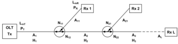
First, a general formula for calculation of optimized splitting ratios is derived for each passive splitter. For this purpose, a network topology with important parameters concerned is presented in Fig. 1.
Figure 1. Transmission parameters of a bus topology.
Consider the maximum attenuation in PON as:
max mT mRmin
;
,
A
L
L
dB dBm dBm
(5),where the optical levels LmT and LmRmin are defined
for transmitter power PT and receiver power PR and
are specified in the ITU-T recommendations or IEEE standards for each type of PON. The calculations satisfy the condition that each receiver receives optical power PRmin, which takes into
account the specified power reserve. To simplify the calculation, the power reserve includes the attenuation of network branches with bridge taps for the direction from the bus to all receivers Ax1
Perspective Application of Passive Optical Network with Optimized Bus Topology, P. Lafata / 340‐346
Journal of Applied Research and Technology 343
marked Nx1 and Nx2 with splitting ratio Nx1:Nx2 while
Nx1+Nx2=1. The residual attenuation at the second
output of the passive splitter is simply included in the attenuation of network elements Ax.
The attenuations of these network elements correspond to the power transmission functions:
10;
10
x A xH
dB
(6)
The transmission function of the passive splitter in the network element x can be expressed:
min 1 1 2 1 1 ; , Rx x x
T i i
i i
P
N W W
P H N
(7)
If the attenuation of all network elements is the same and if it includes the residual attenuation of the second output of the passive splitter, Ax=A1, it
is possible to further simplify Equation (7):
min 1 1 1 2 1 R x x x T i i
P
N
P H
N
(8)According to the previous equations, the splitting ratios of passive splitters can be calculated:
1,1 ,1 ,1 11
1
x x x xN
N
N
H
(9)Where: min 11 1 R T
P
N
P H
;N
x2
1
N
x1 (10)The maximum number of splitters in cascade is xmax, which corresponds to xmax +1 receivers
(optical network units, ONUs). This maximum value can be calculated using previous equations, and according to the condition of maximum attenuation Amax calculated for the second output
of the last passive splitter: max 1 max
min ,2 1 1 x x R i i
i i T
P
H
N
P
(11)Using (10), Equation (11) can be modified: max 1 max
min ,1 1 1
(1
)
x x R i ii i T
P
H
N
P
(12)The next section presents the specific calculations and comparisons based on Equations (8), (9), (11) and (12), and it brings the solutions by using standard splitters with uniform splitting ratio (50/50%), splitters with individually optimized splitting ratios and splitters with standardized series of splitting ratio from [12].
3. Optimization of Passive Optical Network with Bus Topology
The initial calculation is performed for the standard passive optical splitters with uniform splitting ratios of optical power at their outputs. Then, the following calculations, based on this initial result, are carried out for the passive splitters with specific splitting ratio, and the splitters from the standardized series, with the preset values of splitting ratio, as according to [12]. Common set of basic network parameters and parameters of typical optical elements are as follows:
Passive optical network is a GPON type with attenuation class C, the interval of granted attenuation is therefore Amin = 15
dB, Amax = 30 dB.
The optical fiber used in the entire optical distribution is specified according to the ITU-T G.652 recommendation as a D type fiber [13]. Its attenuation coefficient at 1310 nm is therefore = 0.4 dB/km.
Perspective Application of Passive Optical Network with Optimized Bus Topology,P. Lafata / 340‐346
Vol. 10, June 2012 344
optimal spacing is about 200 m to cover the entire area between them by a structured metallic cabling whose length is limited to 100 m.
The connection of the optical network termination OLT and optical network units ONUs to an optical network is ensured by connector with the insertion loss Ak = 0.2 dB.
The residual loss of all passive optical splitters is Az = 0.9 dB.
The attenuation reserve for the compensation of the aging effect and the temperature changes is Ar = 0.5 dB.
The considered configuration containing basic parameters and optical elements described above is illustrated in Fig. 2.
Figure 2. Designed passive optical network with a bus topology.
First, the calculation of attenuation was performed for the passive optical network with parameters described above, using standard passive optical splitters with uniform splitting ratio 50/50%. Based on the results, it can be concluded that with regard to maximum attenuation Amax for the C class of
GPON, it is possible to use only 7 standard passive splitters with constant splitting ratio, which means only 8 optical network units (ONUs) can be connected to the optical infrastructure, as illustrated in Fig. 3. Moreover, some network branches with bridge taps do not meet the minimum attenuation Amin = 15 dB. Therefore, it is
necessary to provide the correction by using additional attenuators for increasing the attenuation of some network branches with bridge taps, which is presented in Fig. 4. The diagrams below present the evolution of attenuation in bridge tap branches before and after the correction using additional attenuators.
Figure 3. The attenuation of network branches with bridge taps before its correction.
Figure 4. Performing the correction of the branches attenuation by additional attenuators.
The next calculation considers the use of asymmetric passive splitters with a non-uniform splitting ratio, which can be precisely optimized for the specific situation. These splitting ratios were individually calculated for each passive optical splitter according to Equations (1), (2), (4) and they were rounded to two decimal places in their percentage expression. The initial idea of a successful optimization process is the achieving balanced attenuation values of all the bridge tap branches, which should attain in an ideal state for the variant GPON class C the Amax value of
30 dB, as presented in Fig. 5.
Perspective Application of Passive Optical Network with Optimized Bus Topology, P. Lafata / 340‐346
Journal of Applied Research and Technology 345
Through optimization, the balanced values of total attenuation are reached in all network branches with bridge taps. It is possible to connect 23 passive splitters to the optical infrastructure. Only for the last of the optical splitters, the value of bus branch attenuation exceeds the limit of Amax,;
hence, the maximum number of ONUs that can be connected to the infrastructure is definitely 23. The calculated values of the splitting ratio for each splitter are presented in Fig. 6.
Figure 6. Splitting ratios of individually optimized splitters.
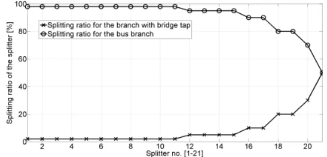
The previous calculation stands for an ideal case in which it is possible to adjust the splitting ratio of each passive splitter individually, and the ratio can be specified with sufficient accuracy (at least two decimal places in its percentage expression). However, in practical applications, it is difficult to achieve such precise adjustment and, above all, it would be very expensive. For this reason, some standardized series of splitters with the most frequently used splitting ratios are produced. One example of a standardized series of the most used splitters can be obtained in [12] and used for the calculation and further optimization. The splitters included in this series have splitting ratio: 2/98%, 5/95%, 10/90%, 20/80%, 70/30% and 50/50 %. Performing appropriate calculations give following results of the attenuation for all network branches and main bus branch and these results are presented in following Fig. 7.
Figure 7. The attenuation of network branches with bridge taps for standardized series of splitters.
The maximum number of splitters is reduced to 21, since a standard series of splitters with constant splitting ratio is used, comparing with the previous optimization using splitters with individually optimized specific values of splitting ratios. However, both optical network units can be connected to the last splitter, which gives the possibility to connect 22 ONUs to the optical infrastructure. The most significant difference can be observed for the splitters with the most non-uniform value of splitting ratio (the lowest splitting ratio in the direction of the network branch with bridge taps, Fig. 5 vs. 7). These splitters are placed at the beginning of the optical distribution network (the splitters closest to the OLT). For this reason, it is not possible to reach a balanced (and maxed) overall attenuation Amax of several
branches with bridge taps, although the attenuations of branches are close enough to the Amax value and meet the requirements for the
minimum value of Amin and thus it is not necessary
to use additional attenuators. Calculated splitting ratios for standardized series of splitters [12] are presented in Fig. 8.
Figure 8. Splitting ratios of splitters selected from the standardized series.
4. Conclusions
Perspective Application of Passive Optical Network with Optimized Bus Topology,P. Lafata / 340‐346
Vol. 10, June 2012 346
case of using standardized series of asymmetric splitters 22 ONUs. The difference between these two solutions is not significant. However, the demands on accuracy and the manufacturing expenses of individually optimized splitters can disqualify this solution from getting eventually applied, as compared to splitters with standardized splitting ratios. Therefore, the optimum design uses the standardized series of splitters, which offers more efficient utilization of total insertion loss for the GPON type class C in comparison with the splitters with uniform splitting ratio.
Both optimized designs, described in the previous chapter, offer attractive and promising alternatives for the construction of local optical high-speed data networks with a bus topology. The use of passive optical networks with shared capacity of 1 Gbps or 10 Gbps combined with the optimization process and since the suitable passive splitters with the non-uniform splitting ratio are employed, an efficient network infrastructure can be designed with many optical network units interconnected. This proposal can be successfully used, e.g., for a local backbone data network, connecting all the local data nodes or access points in large buildings and large industrial complexes.
Acknowledgements
This paper was supported by the Grant Agency of the Czech Technical University in Prague, grant No. SGS 10/275/OHK3/3T/13. The support was also provided by grant No. VG20102015053 - The modern structure of photonic sensors and new innovative principles for intrusion detection systems, integrity and protection of critical infrastructure (GUARDSENSE).
References
[1] J. Vodrazka, “Multi-carrier Modulation and MIMO Principle Application on Subscriber Lines,”
Radioengineering, vol. 16, no. 1, pp. 24-30, 2007.
[2] P. Lafata and J. Vodrazka, “Modeling of Transmission Functions and Crosstalk in Metallic Cables for Implementation of MIMO Concept,” Radioengineering, vol. 18, no. 4, pp. 491-496, 2009.
[3] C. F. Lam, “Passive Optical Networks: Principles and Practice”, Burlington, USA: Academic Press of Elsevier Inc., 2007, pp. 21–56.
[4] R. Roka, “The Utilization of the HPON Network Configurator at Designing of Passive Optical Networks,” in Telecommunication and Signal Processing - 33rd International Conference, Baden near Vienna (Austria), August 2010, pp. 444-448.
[5] ITU-T: G.984.1 - Gigabit-capable passive optical networks (GPON): General characteristics (online), ITU-T. Available from: http://www.itu.int/rec/T-REC-G.984.1-200803-I/.
[6] IEEE Standard 802.3ah-2004, Ethernet in the First Mile (online), IEEE. Available from: http://ieee802.org/3/efm/.
[7] IEEE Standard 802.3av-2009, Amendment 1: Physical Layer Specifications and Management Parameters for 10 Gb/s Passive Optical Networks (online), IEEE. Available from: http://www.ieee802.org/3/av/.
[8] ITU-T: G.987.1 - 10-Gigabit-capable passive optical network (XG-PON) systems: Definitions, Abbreviations, and Acronyms (online), ITU-T. Available from: http://www.itu.int/rec/T-REC-G.987-201001-I.
[9] S. Xia et al., “Tunable optical splitter technology,” in Proceedings of International Society for Optics and Photonics, Soul (Korea), 2002, pp. 146-157.
[10] Z. Yun et al., “A 1x2 Variable Optical Power Splitter Development,” Journal of Lightwave Technology, vol. 24, no. 3, pp. 325-336, 2006.
[11] G. M. Pacheco et al., “Variable optical attenuator using double acousto-optic modulator,” Annals of Optics, vol. 29, no. 1, pp. 207-216, 2006.
[12] PLC Asymmetric Splitters (online), SQS Vlaknova optika a.s. Available from: http://www.sqs-fiber.cz.
[13] ITU-T: G.652 - Characteristics of a single-mode optical fiber and cable (online), ITU-T. Available from: http://www.itu.int/rec/T-REC-G.652-200506-I/