Abstract— Bending deformation of a Flemion-based Ionic conducting Polymer-Metal Composites (IPMCs) upon applied high electric field across its thickness is dominated by non uniform hydration distributioninduced by electro-osmosis and electrolysis of water. Especially, Carboxylic acid group in Flemion provide the membrane with specific features which will lead to the change of equilibrium hydration state and provide improved performance as actuator material, which makes it different from Nafion based on perfluorinated sulfonic acid group. In the present study, finite element formulation is conducted for the basic field equations governing electroche-mical-mechanical response of a gold plated Flemion actuator including the effect of non uniform equilibrium hydration induced by pH distribution due to electrolysis of water. Some numerical studies are carried out in order to show the validity of the present formulation.
Index Terms— Computational Mechanics, Finite Element Method, Ionic conducting Polymer-Metal Composites, Electro-chemical-Mechanical Analysis
I. INTRODUCTION
Ionic conducting Polymer-Metal Composites (IPMCs) have recently attracted a great deal of interest as an intelligent material for artificial muscles, robotics and MEMS due to advantages including low required voltage, high compliance, lightness and flexibility [1],[2].
The platinum plated Nafion [3] (perfluorosulfonic acid membrane made by Dupont) and gold plated Flemion [4] (perfluorocarboxylic acid membrane made by Asahi Glass) are commonly used as polyelectrolyte in IPMCs applications. When a Nafion-based IPMCis subjected to an electric field, mobile cations move quickly toward the cathode side. Then, large bending motion occurs toward the anode side in a short time due to the sudden movement of hydrated cation to the cathode side, followed by slow recovery of the bending deformation due to the diffusion of free water molecules to the anode side.Unlike Nafion-based IPMCs, Flemion-based IPMCs have no back relaxation during its actuation, namely the deformation is stable as long as the voltage is applied. Furthermore, Flemion-based IPMCs show large deformation with time though its response to electric field is delayed in comparison with that of Nafion-based IPMCs.
Nemat-Nasser et al. [3],[11] have examined variousaspe-
Manuscript submitted November 12, 2008.
Woosang JUNG is with the Institute of Industrial Science, University of Tokyo, 4-6-1 Komaba, Meguro-ku, Tokyo 153-8505, Japan.( E-mail : [email protected]).
Yutaka TOI is with the Institute of Industrial Science, University of Tokyo, 4-6-1 Komaba, Meguro-ku, Tokyo 153-8505, Japan. (Correspond- ing author : TEL +81-3-5452-6178, FAX +81-3-5452-6180, E-mail : [email protected]. ac.jp).
cts of Nafion- and Flemion-based IPMCs, providing micro-electro-mechanical modelwhich account for the coupled ion transport, electric field and elastic deformation. Guilly et al. [8] proposed the mesoscopic continuum model for the electrochemical process including the electrolysis of water and conducted the numerical experiment which shows the validity of the model qualitatively, not quantitatively. One-dimensional and two-dimensional finite element formulation for the basic equations governing the electrochemical behavior of Nafion-pt IPMC actuators is only given as a first trial in the development of computational system for the modeling of IPMC actuators by Toi and Kang [5],[6].
Although a large amount of research activity has been devoted to the study of IPMC-based actuators, computational tools useful for the design of Flemion-based IPMCs with high precision have not been developed yet. The purpose of the present study is to establish the computational system which predicts the electrochemical-mechanical behavior of Flemion-based IPMCs. Firstly, the one-dimensional basic equations governing the electrochemical behavior of Flemion-based IPMC beam are discretized by the Petrov-Galerkin finite element method [7]. In addition, the computational system for the deformation response of the Flemion-based IPMC beam is developed by treating the evaluated eigenstrain obtained in electrochemical analysis as initial strain of the three-dimensional finite element analysis based on the initial strain method.
II. FINITE ELEMENT FORMUALTION
The finite element formulation for the two dominant electrochemical processes [8],[9] which induce the bending deformation of a Flemion-Au IPMC beam as shown in Fig.1 is conducted.
Flemion membrane Au layer
(+) (-)
L b
d
x
y z
Fig.1 Au-Flemion membrane model
When a gold plated Flemion membrane is subjected to the electric field, the mobile cations moves to cathode side carrying with them water molecules. This process, which is called electro-osmosis, results in non uniform hydration distribution and deforms the Flemion membrane.
Finite Element Analysis of Ionic-Conducting Polymer
Metal Composite Actuators Using Flemion
In the case of Flemion, hydration also changes with pH. The acid group in Flemion is carboxylic acid and gels containing carboxylic acid show a large hydration change with pH [8],[9]. This is due to the change in ionization state of the carboxyl group. Consequently, a non uniform pH distribution result in non uniform equilibrium hydration distribution and the Flemion membrane is bent, which is called equilibrium hydration effect.
Electrochemical analysis for electro-osmosis and equilib- rium hydration effect due to the electrolysis of water is conducted by one-dimensional mesoscopic continuum model. The initial concentrations inside the membrane are calculated from the concentrations outside the membrane by Donnan Equilibrium condition. The finite element formulation for electrochemical-mechanical equations governing these processes is described below.
A. Electro-osmosis effect
The flux of ith ion( i=1,2,3: 1=Na+, 2=H+,3=OH−) with- in the Flemion membrane is given by Nernst-Planck equa- tions [9]:
⎥ ⎥ ⎦ ⎤ ⎢
⎢ ⎣ ⎡
+ ∂ ∂ − =
Γ cE
z z c
D i
i i i i i i φ ϕ µ
(1)
where Γiis the ith ionic flux. ci is the concentration of ion i
having intramembrane diffusivity Di, electrical mobilityµi,
and valence zi. The mobility µican be calculated from the
diffusion constant Di based on Nernst-Einstein relation,
F z RT
D/µi= / i . E is the local electric field and φ is the
membrane porosity. Material coordinates ϕ can be trans- formed to the Lagrangian coordinates x associated with the solid membrane matrix:
dx H dx H
d (1 ) (1 eq)
0
+ ≈ + =
ϕ (2)
When a Flemion membrane is under an electric field, sodium ions are subjected to the electrostatic force and move to the cathode side. To obtain a simple solution for the electro-osmosis effect, we assume that the electric field is only due to the redistribution of sodium, because it is the majority carrier of current. J is the current densityand F is faraday constant:
1
Γ ≈ Γ ∑
=F z F
J i i (3)
Sodium ions are neither created nor consumed. Continuity condition in the membrane is expressed as follows:
( )
x F J
x t c
Heq
∂ ∂ − = ∂
Γ ∂ − = ∂
∂ ( )
1 1
α α
o (4)
where 0
eq
H is the initial equilibrium hydration andαis the total membrane area normalized to its initial area. In the macroscopic level, the current density and sodium concentration can be assumed to be uniform in Flemion membrane. Electric field is obtained by using the (1) and (3):
1 1 1 1
1
1 1
1 1 1
c F
J c c
x c D E
φµ φµ
φµ φ
= Γ = ∂ ∂ + Γ
= (5)
Interstitial fluid flow relative to the solid matrix can be obtained by using fluid pressure and electro-osmotic force as described by an augmented Darcy’s Law [9]:
(
)
⎥⎥⎦⎤ ⎢
⎢ ⎣ ⎡
+ ∂ ∂ + − ′
= c FE
x P H k
U m
eq
0
1 1
(6)
where
x p x P
∂ ∂ = ∂ ∂
(7)
(
)
⎟⎟⎠ ⎞ ⎜
⎜ ⎝ ⎛
− = +
− = +
− = =
v E M H
H H e H
H H M Me
p Flemion
eq eq eq
eq
2 1 3 , 1 , 1
(8) where k′is the hydraulic permeability, Pis the fluid pressure,
p is the swelling stress, M is the bulk modulus, cmis the
concentration of fixed ions, H is hydration, e is volumetric strain, EFlemion is the elastic modulus of Flemion membrane.
Changes in hydration are calculated from the divergence of fluid flow according to the continuity condition (9). The initial and boundary conditions are given as follows (10) and (11), respectively:
( )
(
)
x
FE c x p
H k
x U t
H
m eq
∂
⎟ ⎟ ⎠ ⎞ ⎜
⎜ ⎝ ⎛
⎟ ⎟ ⎠ ⎞ ⎜
⎜ ⎝ ⎛
− ∂ ∂ + ∂ = ∂ ∂ − = ∂
∂ 1 0
1 '
α α
(9)
3463 . 0 ) 0 , (x =
H (10)
( ) ( )
0,t =U d,t =0U (11) The finite element formulation based on Petrov-Galerkin method [7] for (9) leads to the following equation.[ ]W is
weighting function matrix:
( )
( )
(
)
( )( )
, 0 1, ]
[
2
2
0 '
= ⎟ ⎟ ⎠ ⎞ ⎜
⎜ ⎝ ⎛
∂ ∂ + − ∂ ∂
∫
dxx t x P H k t
t x H W
e V
e eq e
T α
(12)
Hydration is assumed to be a linear function of the element coordinate x in each element as shown in the following equation.
[ ]
N is the shape function matrix:( )
( )
{
}
[ ]
{ } [
( )]
( ) ( )⎪⎭ ⎪ ⎬ ⎫ ⎪⎩ ⎪ ⎨ ⎧ =
= e
j e i j i e e
H H N N H N t x H
, ,
, (13)
The following ordinary differential equation for hydration is obtained by substituting (13) into (12):
( )
[ ]
Ae {H&( )e}+[ ]
F( )e{ }
P( )e +{G( )e}=0(14)
[ ]
=∫
) ( ] [ ] [ e V T e dx N WA (15)
[ ]
(
)
∫
∂∂ ∂ ∂ + = 0 ' ) ( [ ] [ ]1 Ve
T eq e dx x N x W H ak
F (16)
(
)
( )
i j T eq e x x x t x P W H k G ∂ ∂ + − = [ ] , 1 } { 0 ' ) ( α (17)B. Equilibrium hydration effect
When a voltage higher than 1.2V is applied to electrodes, electrolysis of water takes place at electrodes. H+ions are created at the anode and −
OH ions are created at the cathode. The continuity equation for concentration of H+ is given by the following equation. The initial and boundary conditions are given as follows (21) and (22), respectively:
( )
( )
(
)
⎟⎟⎠ ⎞ ⎜ ⎜ ⎝ ⎛ ∂ ∂ + ∂ ∂ ≈ ∂ Γ ∂ − = ∂ ∂ x c H D x x t c H eq eq 2 0 2 2 2 0 1 φ α α (18) b c cc2 = 2+ 2 (19)
) ( 1 2 2 2 c K c c H c s mo eq b + =
o (20)
where cb
2is the concentration of
+
H that bind to −
COO :
(
3)
2 2(x,0) 1.0605 10 mol/m
c = × − (21)
(
)
( 0)1 0 1 ,
2 = + =
Γ atx
F J H is electrolys eq φ
(atx d)
n= =
Γ2, 0 (22)
The concentration of H+ is assumed to be a linear function
of the element coordinate x in each element as shown in the following equation: ( )
( )
{
}
[ ]
{ }
( )[
]
( ) ( ) ⎪⎭ ⎪ ⎬ ⎫ ⎪⎩ ⎪ ⎨ ⎧ = = e j e i j i e e c c N N c N t x c , 2 , 2 22 , (23)
where c2i and c2j are the nodal concentration of +
H . The following equation is obtained by the finite element formulation for (18) based on Petrov-Galerkin method[7]:
[ ]
( )( )(
)
( )( ), 01 ,
0
2 2
0 2 =
⎟⎟ ⎟ ⎠ ⎞ ⎜⎜ ⎜ ⎝ ⎛ ⎟ ⎟ ⎠ ⎞ ⎜ ⎜ ⎝ ⎛ ∂ ∂ + ∂ ∂ − ∂ ∂
∫
Vee eq e eq T dx x t x c H D x t t x c H
W α φ (24)
Substituting shape functions of (23) into (24), the following ordinary differential equation is obtained:
( )
[ ]
{ ( )}[ ]
( ){ }
( ) { ( )} 02 2
2 2 + 2 + =
e e e e e G c F c
A & (25)
where
[ ]
=∫
0 ) (2 [ ] [ ]
e V
T eq
e H W N dx
A (26)
[ ]
(
)
∫
∂∂ ∂ ∂ + = 0 2 ) ( 2 ] [ ] [1 Ve
T eq e dx x N x W H D a
F φ (27)
[ ]
(
)
( )( )
i j e eq T e x x x t x c H D WG ⎟⎟
⎠ ⎞ ⎜ ⎜ ⎝ ⎛ ∂ ∂ + − = , 1 } { 2 0 2 ) (
2 αφ (28)
Next, the continuity equation for concentration of OH− is given by the following equation. The initial and boundary conditions are given as follows (30) and (31), respectively:
( )
( )
(
)
⎟⎟⎠ ⎞ ⎜ ⎜ ⎝ ⎛ ∂ ∂ + ∂ ∂ = ∂ Γ ∂ − = ∂ ∂ x c H D x x t c H eq eq 3 0 3 3 3 0 1 φ α α (29)(
3)
7 3(x,0) 9.4295 10 mol/m
c = × − (30)
(
0)
0
1 ,
3 = =
Γ atx
(
)
(
atx d)
F J H is electrolys eq n = + − = Γ 1 0 , 3 φ (31)
Finally, the following ordinary differential equation for concentration of OH−is obtained by the Petrov-Galerkin finite element formulation:
( )
[ ]
{ ( )}[ ]
( ){ }
( ) { ( )} 03 3
3 3 + 3 + =
e e e e e G c F c
A & (32)
where
[ ]
=∫
0 ) (3 [ ] [ ]
e V
T eq
e H W N dx
A (33)
[ ]
(
)
∫
∂∂ ∂ ∂ + = 0 3 ) ( 3 ] [ ] [1 Ve
T eq e dx x N x W H D a
F φ (34)
[ ]
(
)
( )( ) i j e eq T e x x x t x c H D WG ⎟⎟
⎠ ⎞ ⎜ ⎜ ⎝ ⎛ ∂ ∂ + − = , 1 }
{ () 30 3
3 αφ (35)
The interaction between H+ and −
OH ions is a complete reaction and mathematically discontinuous. To obtain the concentration of H+ andOH− at t+∆t, we will introduce a virtual time t+∆t′ at which each ion has a virtual concentration distribution. The total concentrations of H+
and OH− are compared at a virtual time t+∆t′. Then the smaller concentration is subtracted from the larger to model the complete reaction. Finally, the concentrations of +
H and
−
OH at time t+∆t is obtained by using dissociation constants
in (36) or (37) [8]. IF 2+∆′+ t2+∆t′− 3t+∆t′≥0
b t
t c c
c t t t t b t t t t b t t c c c c
c+∆ + +∆ = 2+∆′+ 2+∆′− 3+∆′ , 2 2 t t w t t c K c +∆ = +∆
2
3 (36)
ELSE IF
(
t t bt t)
t t t t c c c
c3+∆ = 3+∆′− 2+∆′+ 1,+∆′
t t w t t c K c +∆ = +∆
3
0 2 4 6 8 10 12 0.15
0.20 0.25 0.30 0.35 0.40 0.45
Equilibrium Hydration
H eq
Solution pH
Fig.2 Relation between equilibrium hydration and pH
0 2 4 6 8 10
0.00 0.04 0.08 0.12 0.16 0.20
Curren
t ( A
)
Time ( sec ) (a) Total current input
0 2 4 6 8 10
0.000 0.002 0.004 0.006 0.008 0.010
Cu
rre
nt
( A )
Time ( sec )
I
electrolysis
=3.1mA
(b) Electrolysis current
Fig.3 Input current profileunder a step voltage (3V)
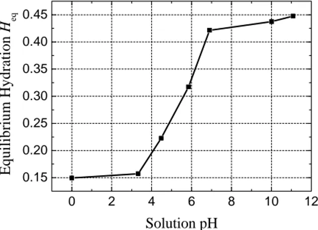
In dilute solutions, activity is approximately equal to the numeric value of the concentration of H+. The formula for
calculating pH is :
(
3)
2
10 10
log
pH=− c × − (38) Fig.2 shows the relation between hydration of the membrane and intramembrane pH. A small change in pH due to electrolysis of water will lead to a significant change in equilibrium hydration Heq , because ionization state of the
carboxyl group in Flemion membrane is changed with increasing or decreasing pH [7],[8]. At low pH, the group is in acid form(COOH) and it is neutral. At high pH, the group
is ionized (COO−).
Table 1 Material parameters Concentration of sodium ion c1=1890
(
mol/m3)
Molar concentration of ionizablegroups per volume of solid polymer
(
3)
/ 2880mol m
cs
mo=
Hydraulic permeability of the
polymer membrane k 1.05 10
(
m /Ns)
4 20
'= × −
Elastic modulus of Flemion membrane
(
)
49 . 0
6 . 150 =
=
Flemion Flemion
v
MPa E
Elastic modulus of gold layer
(
)
49 . 01946
= =
Gold Gold
v
MPa E
Electrolysis current Ielectrolysis=0.0031
( )
AFaraday constant F=96485.3415
(
C/mol)
Concentration of fixed ion(COO- )
(
)
3 3
/ 10 89 .
1 mol m
cm= ×
o
Ion product for water 8
(
3)
2/ 10 0 .
1 mol m
Kw
−
× =
Equilibrium constant K=1.0×10−2.5
(
mol/m3)
Total membrane area normalizedto its initial area α=1.219255 Membrane porosity φ=0.257224 Initial equilibrium hydration Heqo =0.3463
Coefficient of diffusion of H+ D2 9.311 109
(
m2/s)
−
× =
Coefficient of diffusion of OH− D 5.273 109
(
m2/s)
3
−
× =
Intra-membrane mobility 1 2.2 1010
(
m /2 Vs)
−
× = µ
C. Mechanical response
Assuming the material is isotropic, normal eigenstrain components εi are evaluated as follows:
e
z y x
3 1 = = =ε ε
ε (39)
The three-dimensional finite element deformation analysis with eight-node hexahedron element can be conducted by considering the estimated eigenstrain εi as an initial strain
used for the calculation of the apparent external force vector in (42). Stiffness equations for the finite deformation, isotropic and elastic model is given by the total Lagrangian formulation [10].
[ ]
{ }
{ } { }
R eT u f f
K ∆ = ∆ ′ + ′ (40) where
[ ] [ ] [ ]
= + =∫
[ ]
[ ]
[ ]
+∫
[ ] [ ][ ]
′e
e V
T V
T G
T K K B D BdV G S GdV
K
(41)
{ }
∆ ′ =∫
[ ]
[ ]
{ }
∆ ′( )e V
e dV
D B f
ε (42)
where the following notations are used:
[ ]
KT is tangentstiffness matrix;
[ ]
K is the incremental stiffness matrix;[ ]
KGis the geometric stiffness matrix;
[ ]
B is large deformation strain-displacement matrix;;[ ]
D is stress-strain matrix;[ ]
s′ is the stress matrix;[ ]
G is the matrix of the derivatives of the shape function;{ }
∆f′ is the incremental force vector;{ }
∆fR′ isIII. FINITE ELEMENT ANALYSIS OF ELECTROCHEMICAL- MECHANICAL ANALYSIS
The numerical solutions for electrochemical-mechanical behaviors of Flemion-Au IPMC beam were obtained by using the 4th order Runge-Kutta time-integration scheme in the Lagrangian coordinates. The thickness of the Flemion membrane is d=145µmwith a gold layer of 7.5µm thickness. Length is 10µm and width is 3µm.Material parameters and current input data for solving equations are given in Table 1 and Fig.3, respectively. Based on the measured stiffness of bare Flemion and Flemion-based IPMCs [11], the Elastic modulus of Flemion and gold layer are evaluated as shown in Table 1. Ielectrolysis is the current used for electrolysis of water,
which can be assumed to be some amount of total current as described in Fig.3(b).
0 20 40 60 80 100 120 140
0.0 0.5 1.0 1.5 2.0 2.5 3.0
3sec 5sec 7sec 9sec
H
+ concent
rat
io
n
(
x 10
-1
m
o
l /m
3 )
x ( µm )
(a) Over the entire thickness
0 2 4 6 8 10
0.0 0.5 1.0 1.5 2.0 2.5 3.0
3sec 5sec 7sec 9sec
H
+ concentr
ation
(
x 1
0
-1
mol /m
3 )
x ( µm )
(b) Enlarged portion near anode
140 141 142 143 144 145
0.0 0.5 1.0 1.5 2.0 2.5
3sec 5sec 7sec 9sec
H
+ concent
rati
o
n (
x
10
-2
m
o
l /m
3 )
x ( µm )
(c) Enlarged portion near cathode Fig.4 H+ concentration distribution in membrane
A. H+ and OH−distribution
The H+ concentration distribution through Flemion
membrane is shown in Fig.4. The enlarged parts near the anode and cathode side are presented in Fig. 4(b) and 4(c), respectively. H+concentration increases rapidly at the anode side due tothe generation of H+ions induced by electrolysis
of water. Contrary to H+ concentration, OH− increases at the cathode side as shown in Fig.5. The change of H+ concentration at the cathode side and OH− concentration at
anode side is induced by the interaction between H+ and
−
OH ions.
B. Hydration and mechanical response
The equilibrium hydration distribution through Flemion membrane is presented in Fig.6. At anode side, equilibrium
0 20 40 60 80 100 120 140
0 5 10 15 20
3sec 5sec 7sec 9sec
x ( µm )
OH
- c
o
ncent
rat
ion (
x10
-6 m
o
l /m
3 )
(a) Over the entire thickness
0 2 4 6 8 10
0 1 2 3 4
3sec 5sec 7sec 9sec
x ( µm )
OH
- concent
rat
io
n ( x10
-6 m
o
l /m
3 )
(b) Enlarged portion near anode
140 141 142 143 144 145
0.0 0.5 1.0 1.5 2.0
3sec 5sec 7sec 9sec
OH
- c
o
n
ce
n
tr
atio
n
(
x
10
-5 m
o
l /m
3 )
x ( µm )
0 20 40 60 80 100 120 140 0.15
0.20 0.25 0.30 0.35 0.40 0.45
x ( µm )
3sec 5sec 7sec 9sec
E
q
u
ilib
ri
u
m
h
y
d
ra
tio
n
H
eq
Fig.6 Equilibrium hydration distribution
0 20 40 60 80 100 120 140
0.0 0.1 0.2 0.3 0.4 0.5 0.6 0.7
x ( µm )
Hydr
ation
3sec 5sec 7sec 9sec
Fig.7 Hydration distribution
0 2 4 6 8
0 2 4 6 8
Experiment
Pattern-1(Ielectrolysis=3.1mA)
Pattern-2(Ielectrolysis=10% of total current)
Pattern-3(Ielectrolysis=30% of total current)
Pattern-4(Ielectrolysis=50% of total current)
D
ispl
acem
ent
( m
m
)
Time ( sec )
Fig.8 Calculated and experimental displacements hydration decreases dramatically due to the decrease of pH which results from generation of H+ ions. At cathode side, equilibrium hydration increases due to the decrease of H+
ions. Consequently, the steady state at each electrode side is changed, which implies that the relaxation is interrupted or does not take place despite the non uniform hydration distribution.
Fig.7 shows the hydration distribution. At first, hydration decreases rapidly at the anode side and increases rapidly at the cathode side due to the electro-osmosis effect. After a sudden change in hydration, slow relaxation can be seen near the electrodes as electric current goes to zero.
In this study, four cases of electrolysis currents are considered as shown in Fig.8. In the case of pattern-1, elec- tro-osmosis current is assumed to be constant. The calculated results in first 2 sec agree well with the experimental results
[8]. However, the calculated results show the discrepancies with the experiment results after the electrolysis current becomes higher than electro-osmosis current. In the case of pattern-3 and pattern-4, the electrolysis current is assumed to be relatively high. Although the slope of time-histories of tip displacement is good agreement with experimental result, the predicted deformations are small due to the underestimation of electro-osmosis effect. In the case of pattern-2, the calculated results show a good agreement with experimental data. According to the above results, it can be sure that the electro-osmosis effect is dominant compared to the electrolysis effect and the balance between electro-osmosis and electrolysis effect is important to simulate exactly the behaviors of Flemion-based IPMCs.
IV. CONCLUSION
This study has presented a finite element model for the simulation of electrochemical-mechanical behaviors of Flemion-based IPMCs. The proposed model can be expected to be used as a computational tool for the evaluation and the design of the Flemion-based IPMCs.
ACKNOWLEDGMENT
The authors would like to thank Professor Minoru Taya (Center for Intelligent Materials and Systems, University of Washington) and Dr. Guilly (Intel Corporation) for valuable comments and discussions concerning theoretical model.
REFERENCES
[1] K.J. Kim, M. Shahinpoor : ''A novel method of manufacturing three-dimensional ionic polymer-metal composites (IPMCs) biomimetic sensors, actuators and artificial muscles, Polymer 43, pp.797-802(2002)
[2] M.Shahinpoor, Y. Bar-Cohen, J. O.Simpson and J. Smith : ''Ionic Polymer-Metal Composites(IPMCs) as Biomimetic Sensors, Actuators and Artificial Muscles–a Review'', Smart Materials & Structures, Vol.7, pp. R15-R30. (1998)
[3] S. Nemat-Nasser, J. Y. Li : ''Electrochemical response of ionic polymer –metal composites'', Journal of Applied Physics, Vol. 87, pp. 3321-3331.(2000)
[4] K. Onishi, S. Sewa, K. Asaka, N. Fujiwara and K. Oguro: ''Morphology of Electrodes and Bending Response of the Polymer Electrolyte Actuator'', Electrochimica Acta, Vol. 46, pp. 737-743. (2000)
[5] Y. Toi and S. Kang : ''Finite Element Modeling of Electrochemical-Mechanical Behaviors of Ionic Conducting Polymer-Metal Composites'', Transactions of the Japan Society of Mechanical Engineers(A), Vol. 70-689, pp. 9-16. (2004)
[6] S. Kang and Y. Toi : ''Finite Element Analysis of Two-Dimensional Electrochemical-Mechanical Behaviors of Ionic Conducting Polymer Actuators'', Transactions of the Japan Society of Mechanical Engineers(A), Vol. 71-702, pp. 225-232. (2005)
[7] O.C. Zienkiewicz, R.L. Taylor : “ The Finite Element Method, Vol.3, Fluid dynamics (Fifth edition)”, Butterworth Heinemann, pp.15-19 (2000)
[8] M.Le Guilly: ''Development of Ionic Polymer Actuator Arrays'', Ph. D Thesis, University of Washington,pp.3-38(2004)
[9] P.E. Grimshaw, J.H. Nussbaum, A.J. Grodzinsky and M. Yarmush : ''Kinetics of Electrically and Chemically induced Swelling in Polyelectrolyte Gels'', Journal of Chemical Physics, Vol. 93-6, pp. 4462-4472. (1990)
[10] O.C. Zienkiewicz, R.L. Taylor : “ The Finite Element Method, Vol.2, Solid Mechanics (Fifth edition)”, Butterworth Heinemann, pp.312-364 (2000)